
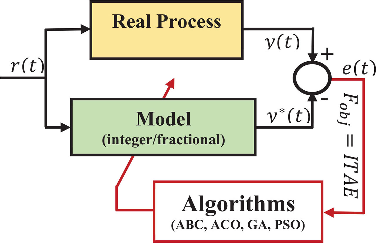
Figure 1.
System identification using algorithms. ABC, artificial bee colony; ACO, ant colony optimisation; GA, genetic algorithm; PSO, particle swarm optimisation.
Table 1.
Characteristic parameters of a DC motor.
| Parameters | Symbol |
|---|---|
| Moment of inertia of rotor | T |
| Motor viscous friction | b |
| Electromotive force constant | Ke |
| Motor torque constant | Kt |
| Electric resistance | R |
| Electric inductance | L |
| Power gain | P |
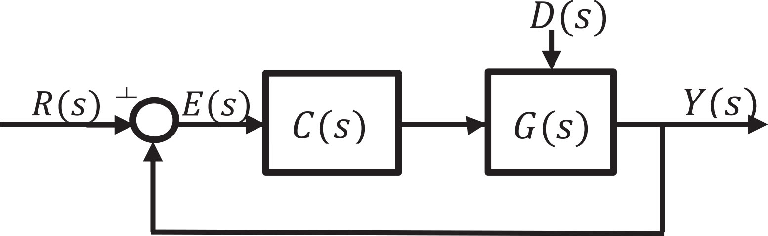
Figure 2.
Closed loop system with FOPID controller. FOPID, fractional-order proportional-integral-derivative.
Table 2.
Adjustment of FOPID using the first method for open-loop response-based parameter.
| P | I | λ | D | μ | |
|---|---|---|---|---|---|
| 1 | −1.0574 | 0.6014 | 1.1857 | 0.8796 | 0.2778 |
| L | 24.5420 | 0.4025 | −0.3464 | −15.0846 | −2.1522 |
| T | 0.3544 | 0.7921 | −0.0492 | −0.0771 | 0.0675 |
| L2 | −46.7325 | −0.4508 | 1.7377 | 28.0388 | 2.4387 |
| T2 | −0.0021 | 0.0018 | 0.0006 | −0.0000 | −0.0013 |
| LT | −0.3106 | −1.2050 | 0.0380 | 1.6711 | 0.0021 |
Table 3.
Adjustment of parameter for FOPID by the second method using the closed-loop response as a basis.
| P | I | λ | D | μ | |
|---|---|---|---|---|---|
| 1 | 0.4139 | 0.7067 | 1.3240 | 0.2293 | 0.8804 |
| Kcr | 0.0145 | 0.0101 | −0.0081 | 0.0153 | −0.0048 |
| Pcr | −0.1584 | −0.0049 | −0.0163 | 0.0936 | 0.0061 |
| 1/ Kcr | −0.4384 | −0.2951 | 0.1393 | −0.5293 | 0.0749 |
| 1/ Pcr | −0.0855 | −0.1001 | 0.0791 | −0.0440 | 0.0810 |
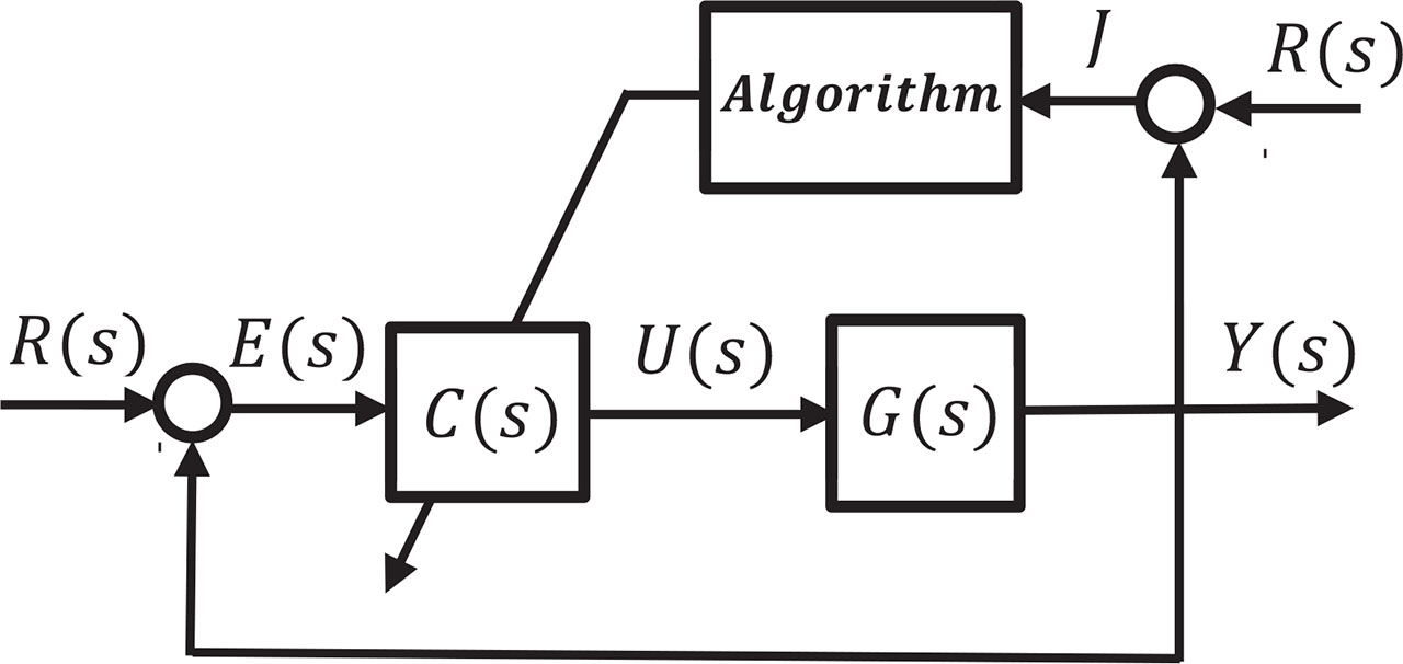
Figure 3.
Optimisation structure with algorithm of tuning FOPID control parameters. FOPID, fractional-order proportional-integral-derivative.
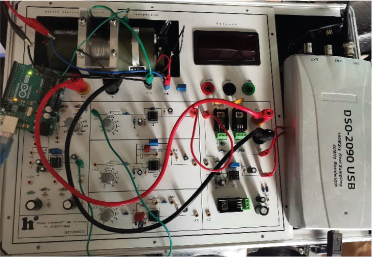
Figure 4.
XK-AUT1003A prototype model.
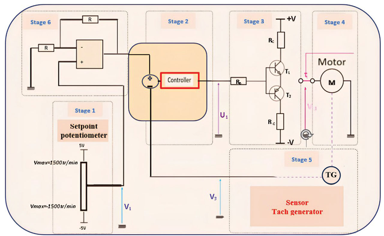
Figure 5.
Block diagram of the experimental setup.
Table 4.
DC motor parameters.
| Parameter | Value | Unit |
|---|---|---|
| Rated voltage | 12 | V |
| No-load speed | 3,000 | RPM |
| No-load current | 0.1 | A |
| Rated torque | 0.05 | Nm |
| Rotor resistance | 2 | Ω |
| Rotor inductance | 15 | mH |
| Rotor inertia | 2.1 × 10⁻⁵ | kg/m2 |
| Command voltage range | −5 to +5 | V |
| Measured speed range | 0–3,000 | RPM |
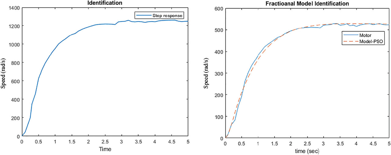
Figure 6.
Open-loop step response-based identification of a DC motor. PSO, particle swarm optimisation.
Table 5.
Optimisation algorithm parameter settings.
| Algorithm | Population size | Number of iterations | Main control parameters |
| PSO | 50 | 100 | w = 0.7, c1 = 1.5, c2 = 1.5 |
| GA | 40 | 100 | Crossover = 0.8, Mutation = 0.05 |
| ABC | 30 | 100 | Limit = 50, food sources = 15 |
| ACO | 25 | 100 | α = 1, β = 2, ρ = 0.5 |
| Number of decision variables | Lower bound | Upper bound | |
| 4 (b,a2,a1,a0) | [0, 0, 0, 0] | [1,000, 1, 10, 10] | |
| 6 (b,a2,α2,a1, α1, a0) | [0, 0, 0, 0, 0, 0] | [1,500, 1, 10, 10, 5, 10] | |
| 5(Kp,KI,λ,Kd,μ) | [0, 0, 0, 0, 0] | [200, 200, 2, 10, 2] |
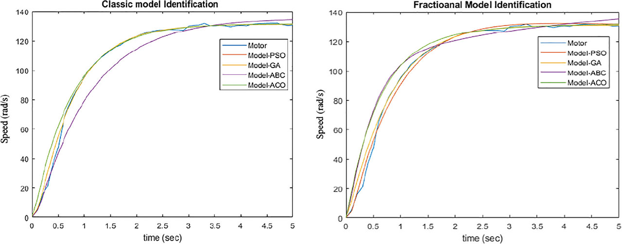
Figure 7.
Comparison of open-loop step responses: integer vs. fractional models. ABC, artificial bee colony; ACO, ant colony optimisation; GA, genetic algorithm; PSO, particle swarm optimisation.
Table 6.
Integer and fractional model with optimal parameter set.
| b | a2 | a1 | a0 | Error (%) | |
|---|---|---|---|---|---|
| ABC | 703.040 | 0.1030 | 4.0911 | 5.3434 | 1.00 |
| ACO | 568.216 | 0.4270 | 4.7000 | 4.1927 | 2.34 |
| GA | 1100.24 | 0.7100 | 6.6710 | 8.3864 | 0.88 |
| PSO | 715.489 | 0.4595 | 4.3391 | 5.4522 | 0.79 |
| b | a2 | α2 | a1 | α1 | a0 | Error (%) | |
|---|---|---|---|---|---|---|---|
| ABC | 1028.74 | 2.0005 | 0.6758 | 3.3143 | 1.1133 | 7.5910 | 0.53 |
| ACO | 87.079 | 0.2540 | 1.2396 | 0.6000 | 0.1950 | 0.2486 | 3.67 |
| PSO | 943.48 | 0.2240 | 2.3584 | 6.3247 | 1.0861 | 7.3010 | 0.22 |
| GA | 785.99 | 1.8313 | 0.7281 | 3.1743 | 1.2083 | 5.9033 | 1.00 |
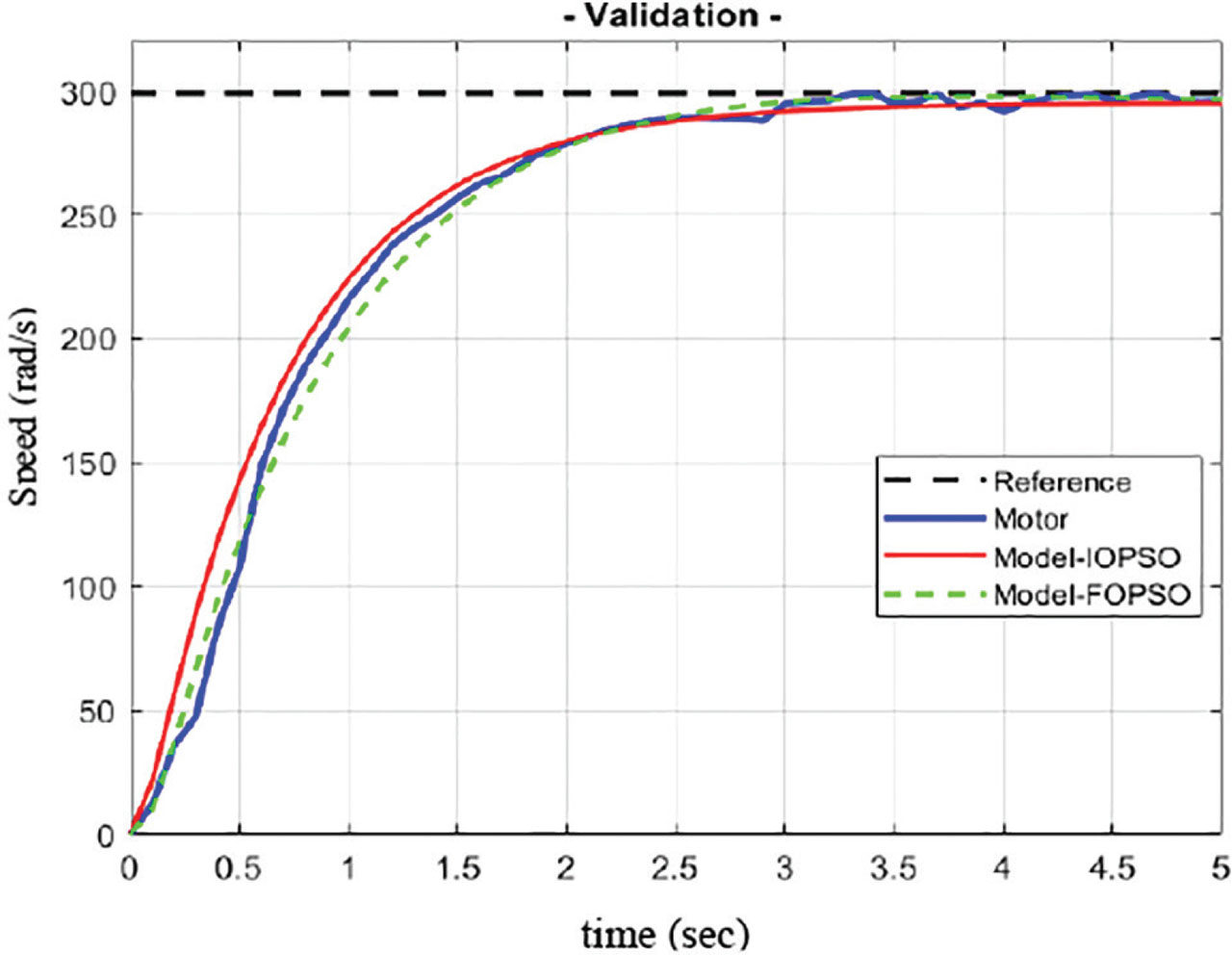
Figure 8.
Validation of model.
Table 7.
Performance assessment of controllers applied to integer and fractional models.
| Kp | KI | λ | Kd | μ | Overshoot (%) | Risetime (s) | Settling time (s) | |
|---|---|---|---|---|---|---|---|---|
| ABCIO | 140.275 | 187.65 | 1.5861 | 0.6831 | 0.9582 | 2.0510 | 1.6875 | 3.5448 |
| ACOIO | 90.420 | 45.157 | 0.9424 | 2.6584 | 0.8912 | 3.5231 | 2.3654 | 2.5447 |
| GAIO | 42.895 | 63.845 | 1.2045 | 2.9821 | 0.9994 | 1.7548 | 1.5483 | 0.9543 |
| PSOIO | 70.548 | 30.448 | 1.0054 | 3.584 | 1.2854 | 1.4545 | 0.5898 | 1.0911 |
| ZN1IO | 91.578 | 70.6554 | 0.9582 | 5.3254 | 1.1415 | 10.554 | 3.1554 | 7.5897 |
| ZN2IO | 101.05 | 60.545 | 1.0254 | 4.5544 | 1.2054 | 11.215 | 4.114411 | 8.1545 |
| ABCFO | 70.6225 | 100.01 | 1.0025 | 0.6831 | 1.1532 | 0.0000 | 1.5487 | 1.9269 |
| ACOFO | 48.600 | 87.617 | 0.9596 | 0.1190 | 0.8729 | 0.0000 | 1.5307 | 1.8454 |
| GAFO | 74.064 | 83.584 | 1.1099 | 1.8281 | 0.8895 | 0.0000 | 1.6928 | 1.0516 |
| PSOFO | 49.219 | 65.352 | 1.0823 | 2.0012 | 0.9899 | 0.0000 | 1.5280 | 1.0911 |
| ZN1FO | 50.215 | 70.225 | 1.2015 | 4.5454 | 0.1521 | 4.4544 | 1,454.5 | 1.8474 |
| ZN2FO | 60.124 | 100.55 | 1.1024 | 5.1544 | 0.9554 | 7.5441 | 1,5485 | 1.77555 |
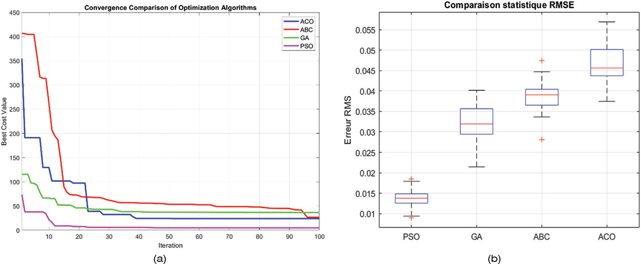
Figure 9.
Convergence behaviour and statistical error comparison of optimisation algorithms. ABC, artificial bee colony; ACO, ant colony optimisation; GA, genetic algorithm; PSO, particle swarm optimisation.
Table 8.
Control effort final values for integer and fractional models.
| Method | PSO | GA | ACO | ABC |
|---|---|---|---|---|
| ‖u‖IO (V) | 6.6222 | 9.1140 | 8.3212 | 9.0678 |
| ‖u‖FO (V) | 6.4791 | 9.1226 | 8.4645 | 8.8118 |
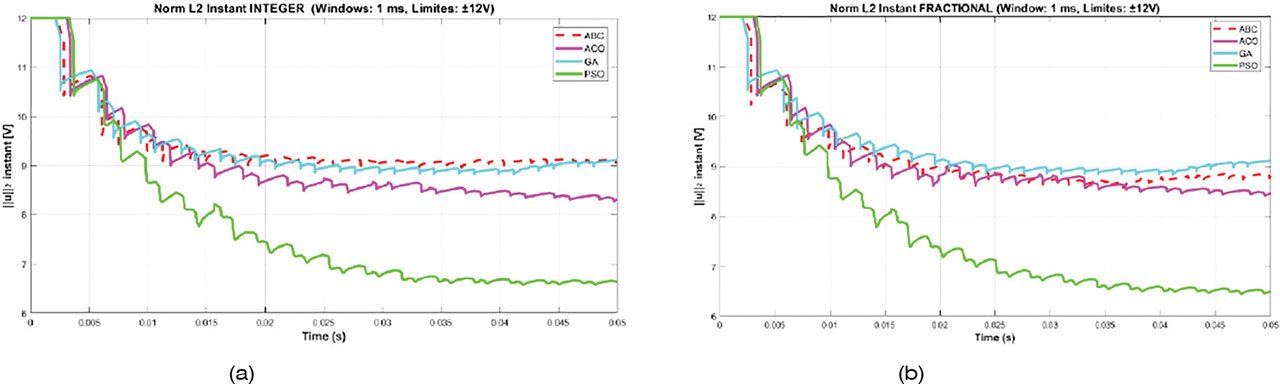
Figure 10.
Effort made control inputs with GIO and GFO. ABC, artificial bee colony; ACO, ant colony optimisation; GA, genetic algorithm; PSO, particle swarm optimisation.
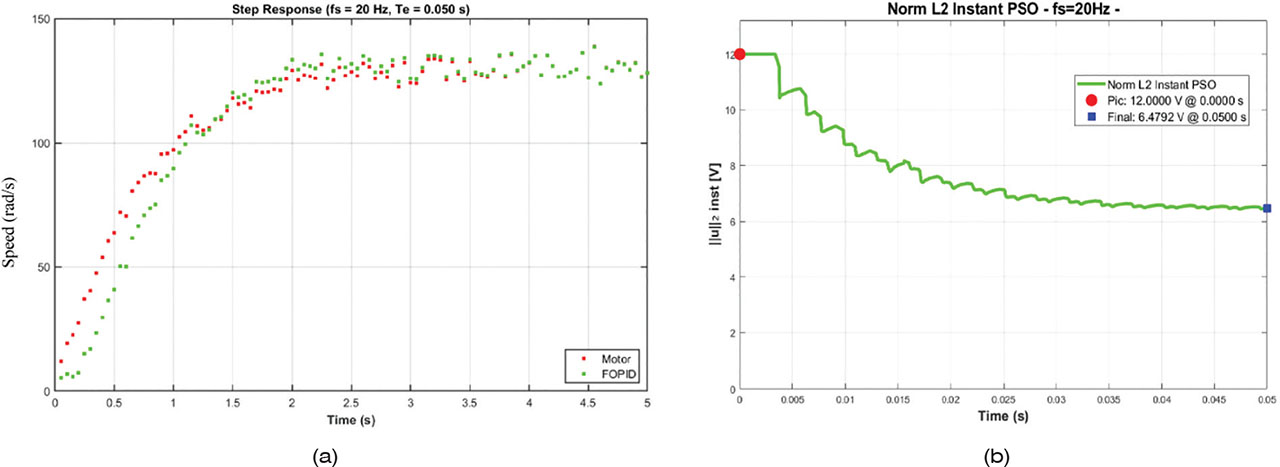
Figure 11.
DC motor closed-loop response under FOPID-PSO control and effort evaluation. FOPID, fractional-order proportional-integral-derivative; PSO, particle swarm optimisation.
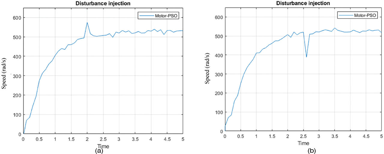
Figure 12.
Closed-loop dynamics with disturbances introduced at 2 s and 2.5 s. PSO, particle swarm optimisation.