
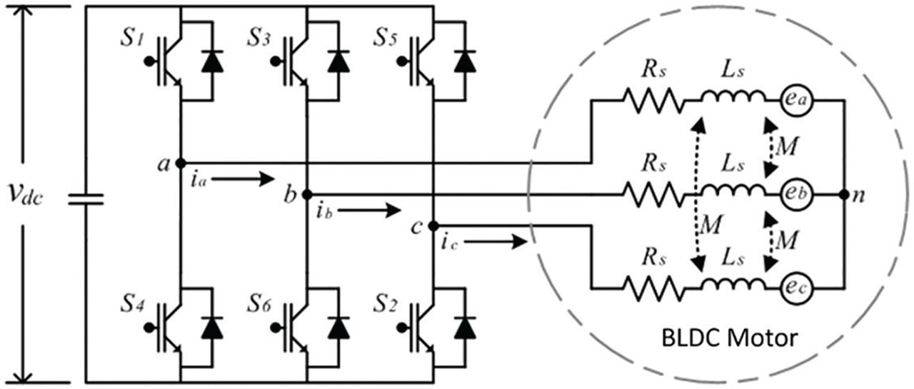
Figure 1.
Block diagram of a BLDC motor drive. BLDC, brushless DC.
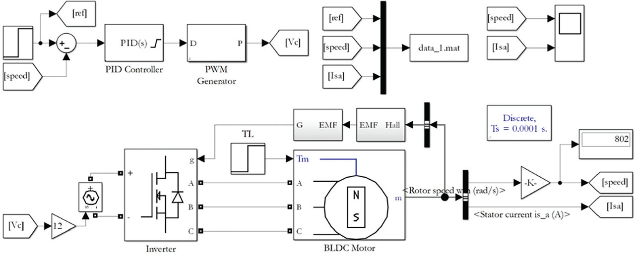
Figure 2.
Simulink diagram of the trapezoidal control of BLDC motors. BLDC, brushless DC; EMF, electromotive force; PWM, pulse-width modulation.

Figure 3.
Motor speed and stator current of the BLDC motor with the trapezoidal control method. BLDC, Brushless DC.
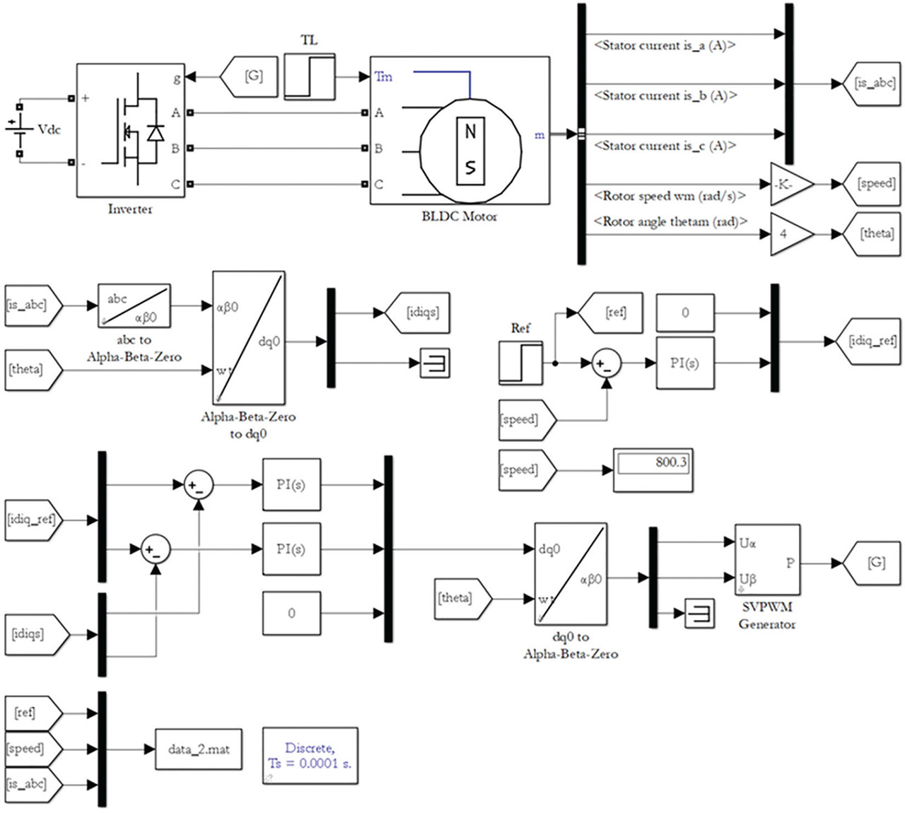
Figure 4.
Simulink diagram of the FOC method of BLDC motors. BLDC, Brushless DC; FOC, field-oriented control; SVPWM, space vector PWM.
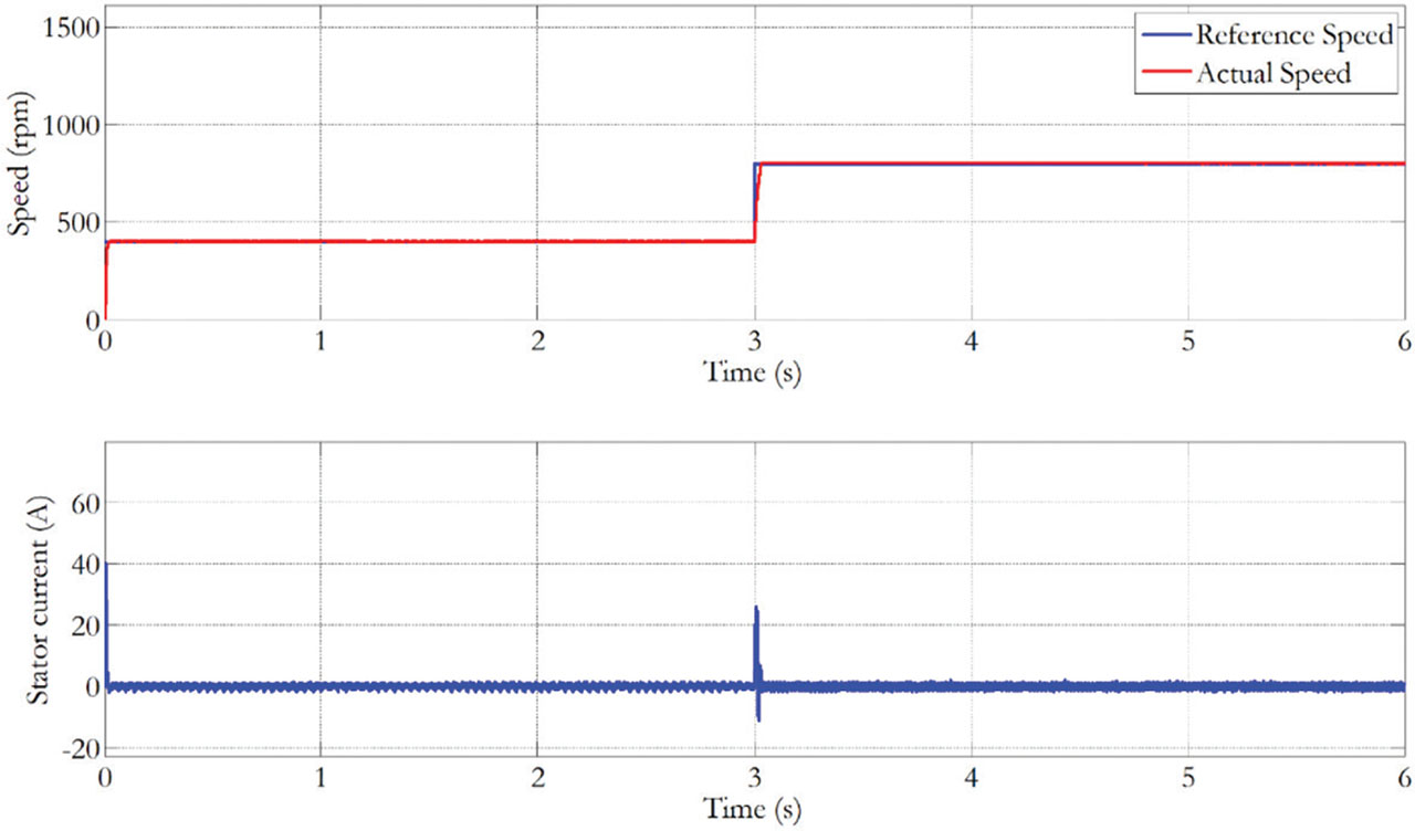
Figure 5.
Motor speed and stator current of the BLDC motor with the FOC method. BLDC, brushless DC; FOC, field-oriented control.
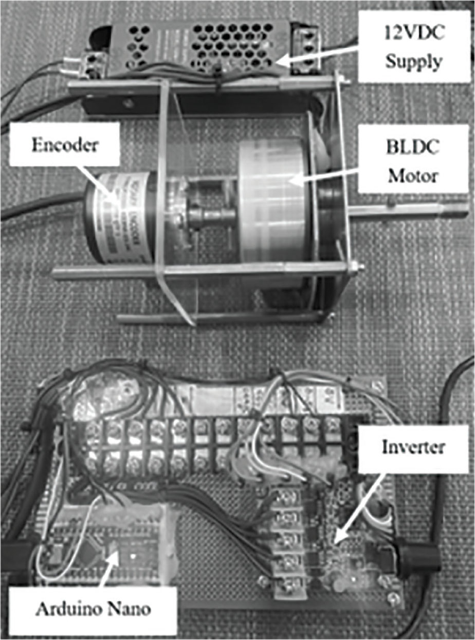
Figure 6.
The hardware. BLDC, brushless DC.
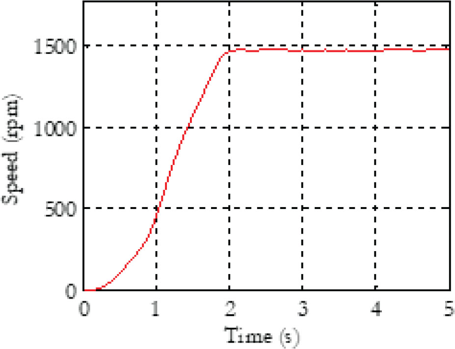
Figure 7.
Response of the real motor speed to a step voltage of 5 V.
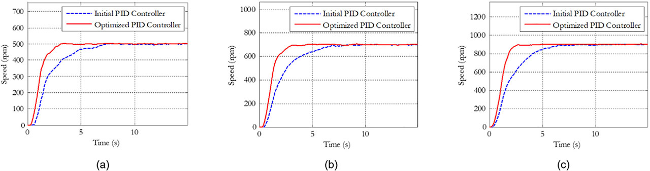
Figure 8.
Motor speed responses for reference speeds of 500 rpm (a), 700 rpm (b) and 900 rpm (c).
Table 1.
Performance comparison between the initial and optimised PID controllers at a speed of 500 rpm.
| Controller | Rise time (s) | Settling time (s) | Overshoot (%) |
|---|---|---|---|
| Initial PID controller | 3.5867 | 6.8628 | 0.0899 |
| Optimised PID controller | 1.6477 | 2.8985 | 0.6736 |