
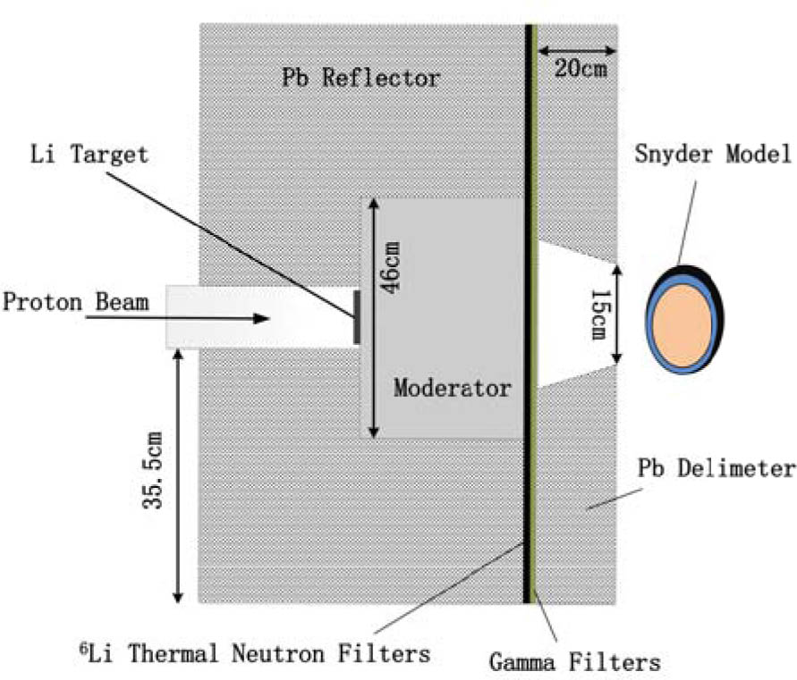
Fig. 1.
The cross-sectional view of a beam shaping assembly for Geant4 simulation.
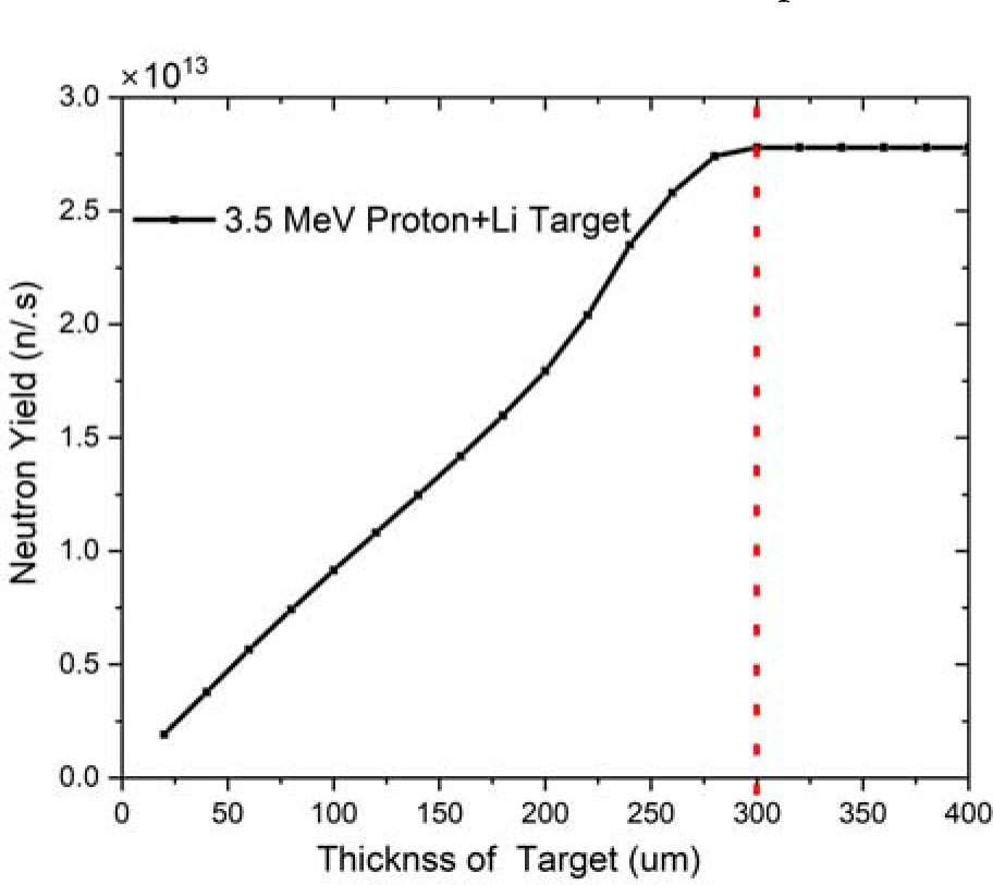
Fig. 2.
The relationship curve between neutron yield and target thickness for a 3.5 MeV proton beam bombarding a lithium target.
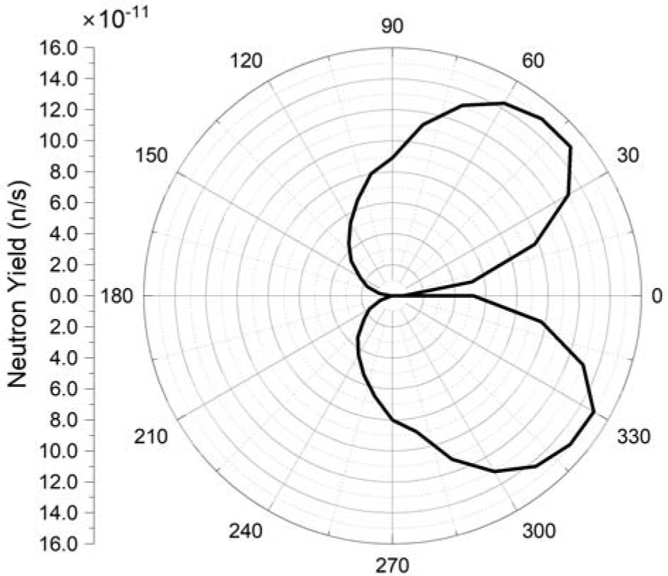
Fig. 3.
Neutron angular distribution with a Li target thickness of 290 μm.
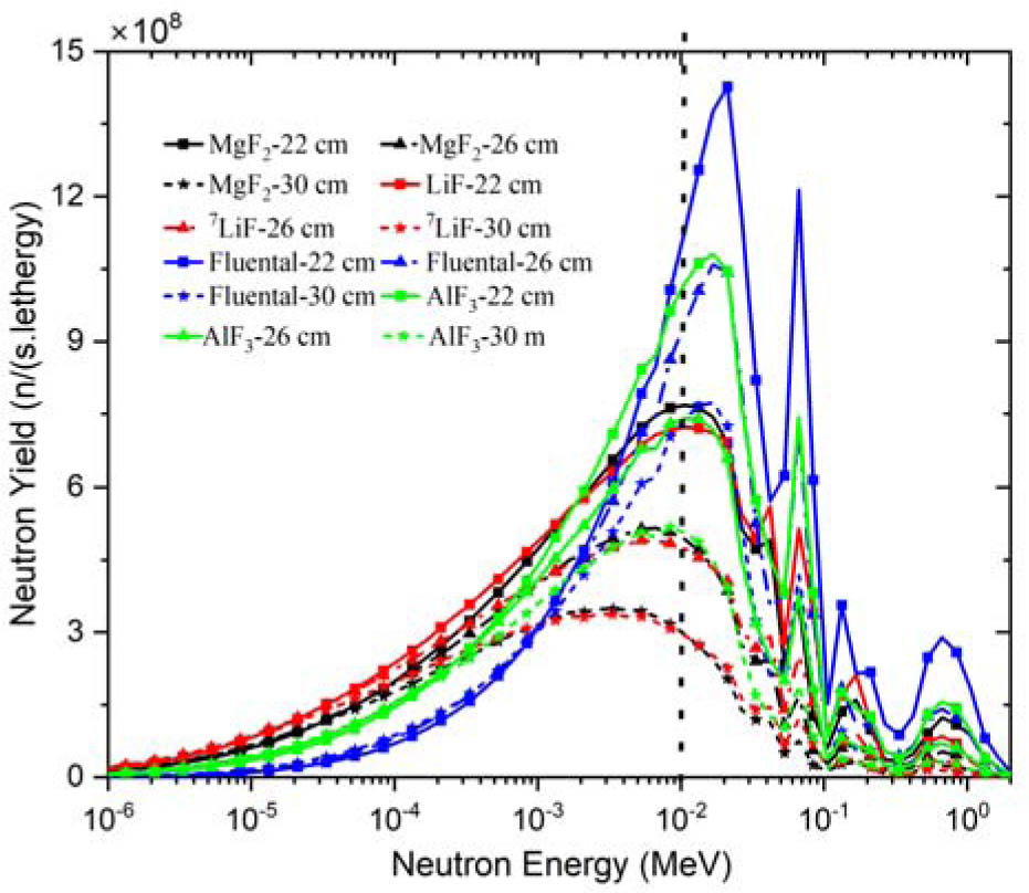
Fig. 4.
The relationship curve between the neutron energy spectrum at the BSA exit and the thickness of the moderated material (MgF2, 7LiF, Fluental, and AlF3) with a range of 22–30 cm.
Table 1.
The dose evaluation parameters of 7LiF in the thickness range of 22–36 cm
| 7LiF thickness (cm) | ADDR (Gy-eq) | Depth of ADDR (cm) | Max dose rate of tumor (Gy-eq) | Advantage depth (cm) | Therapeutic gain (TG) | Treatment time (min) | Max dose rate of tumor (Gy-eq) |
|---|---|---|---|---|---|---|---|
| 22 | 61.1 | 0 | 157 | 8.2 | 1.95 | 12.3 | 33.0 |
| 24 | 42.8 | 0.4 | 135 | 8.8 | 2.21 | 17.5 | 40.5 |
| 26 | 33.2 | 0.4 | 115 | 9.0 | 2.46 | 22.6 | 43.7 |
| 28 | 25.9 | 2 | 99 | 9.2 | 2.61 | 29.0 | 48.5 |
| 30 | 21.7 | 2.4 | 85 | 9.2 | 2.66 | 34.6 | 49.3 |
| 32 | 18.3 | 2.4 | 73 | 9.2 | 2.68 | 41.4 | 50.4 |
| 34 | 15.5 | 2.4 | 63 | 9.2 | 2.70 | 48.6 | 51.0 |
| 36 | 13.2 | 2.4 | 54 | 9.2 | 2.72 | 57.0 | 51.3 |
Table 2.
The dose evaluation parameters of MgF2 in the thickness range of 22–36 cm
| MgF2 thickness (cm) | ADDR (Gy-eq) | Depth of ADDR (cm) | Max dose rate of tumor (Gy-eq) | Advantage depth (cm) | Therapeutic gain (TG) | Treatment time (min) | Max dose rate of tumor (Gy-eq) |
|---|---|---|---|---|---|---|---|
| 22 | 64.1 | 0 | 152 | 8.0 | 1.81 | 12.0 | 32.4 |
| 24 | 47.6 | 0 | 131 | 8.4 | 2.00 | 16.2 | 35.3 |
| 26 | 34.2 | 0 | 109 | 8.8 | 2.28 | 22.2 | 40.6 |
| 28 | 25.8 | 2 | 95 | 9.2 | 2.50 | 29.4 | 46.6 |
| 30 | 20.9 | 2 | 80 | 9.2 | 2.63 | 36.0 | 48.3 |
| 32 | 17.8 | 2.4 | 69 | 9.2 | 2.63 | 42.6 | 48.8 |
| 34 | 15.1 | 2.4 | 59 | 9.2 | 2.63 | 49.8 | 49.3 |
| 36 | 12.9 | 2.4 | 51 | 9.2 | 2.63 | 58.2 | 49.3 |
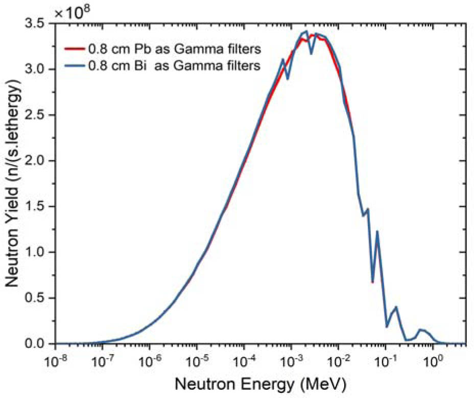
Fig. 5.
Neutron energy spectrum at the BSA exit obtained with 0.8 cm Pb and 0.8 cm Bi as gamma filters, respectively, where the thickness of 7LiF is 30 cm.
Table 3.
The IAEA parameters [14] obtained by using 0.8 cm thick Pb and Bi as gamma filters, respectively, where the thickness of 7LiF is 30 cm
| Parameter | φepi (n/cm−2·s−1) | φth/φepi | Df/φepi (Gy-cm2/n) | Dγ/φepi (Gy-cm2/n) | Current/flux |
|---|---|---|---|---|---|
| IAEA advised | >1.00 × 10⁹ | <0.05 | <2.00 × 10⁻¹³ | <2.00 × 10⁻¹³ | >0.70 |
| Pb 0.8 cm | 1.82 × 10⁹ | 0.005 | 4.22 × 10⁻¹⁴ | 3.31 × 10⁻¹⁴ | 0.71 |
| Bi 0.8 cm | 1.84 × 10⁹ | 0.005 | 4.21 × 10⁻¹⁴ | 3.30 × 10⁻¹⁴ | 0.71 |
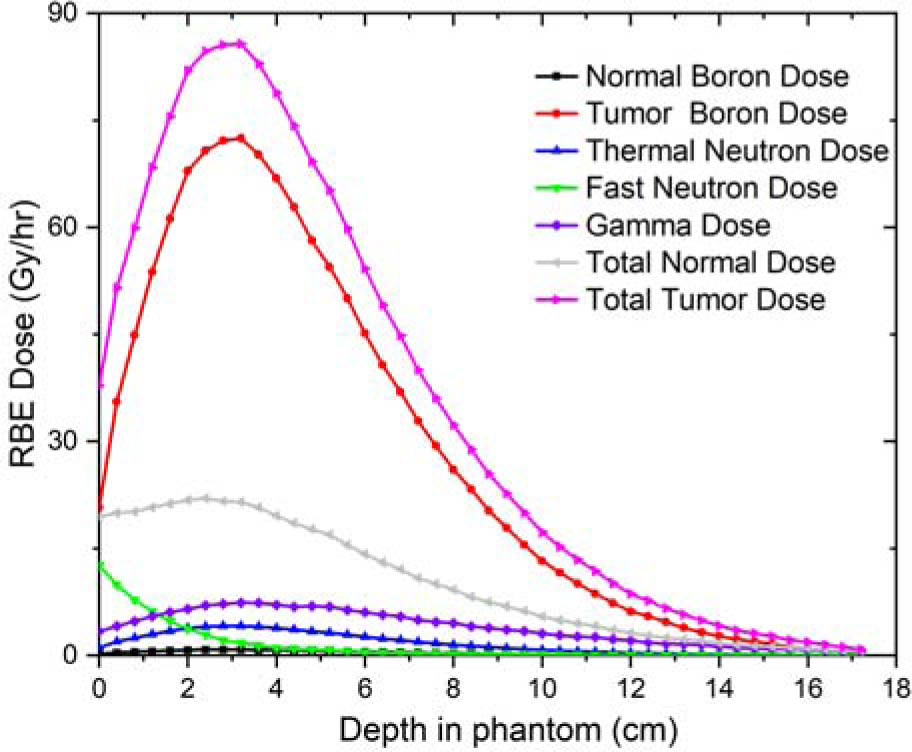
Fig. 6.
The depth-dose curve of the final BSA.