Cyclotrons are widely applied in the field of nuclear medicine, especially in the fields of radiopharmaceuticals and cancer treatment. They are the most cutting-edge radiotherapy technology in the microscopic world for the treatment of tumors with protons and heavy ion rays. The accelerator magnetic field of the superconducting cyclotron is provided by the superconducting coil, which provides binding force and strong focusing force for the particle beam movement. It is an important part because the field configuration distribution directly determines the operation performance of the cyclotron. Therefore, it is necessary to accurately measure the magnetic field, and then analyze the magnetic field performance.
The magnetic field measurement technology has been widely used in navigation aerospace, life science, resource exploration, seismic monitoring, and other fields [1, 2]. In view of the application prospect in many fields, magnetic field sensors with various properties and uses have been developed, such as Hall probes, anisotropic magneto resistive probes, fluxgate magnetometers, superconducting quantum interference devices, and so on [3,4,5,6]. For measuring the strong magnetic fields, the Hall magnetometer and Teslameter are the most widely used magnetic measuring instruments in the market. The measuring magnetic field range is 0.1 mT – 12 T, and the working temperature range is 0–75°C. They are mainly used for measurement and monitoring of environmental magnetic field, residual magnetic field measurement of objects and materials, magnetic shielding efficiency detection, permanent magnet pole distribution measurement, electromagnetic field leakage detection, and so on. Magnetic field sensors are widely used in fields such as national defense and military industry, civilian production, rail transportation, food safety testing, and other fields. However, due to the effects of non-linearity, zero thermal drift, and temperature sensitivity drift, the probe accuracy cannot be guaranteed. Therefore, many scholars have studied how to design calibration devices and control systems to improve the sensor measurement accuracy.
Yang et al. [7] studied the temperature characteristic calibration device of Hall magnetometer. In order to determine that the temperature coefficient and zero temperature drift are the key parameters that affect the accuracy of Hall magnetometer, they carried out research on the calibration device and method according to its working principle, and verified the measurement ability of the device through experiments.
Shen and Xia [8] designed an intelligent calibration system for sensor linearization and temperature compensation. The results showed that the system can meet the requirements of linearization and temperature compensation of silicon piezo resistive pressure sensors.
Chen et al. [9] adopted the voltage ratio measurement method to measure the magnetic induction intensity, to eliminate the influence of the change of excitation current on the measurement. Tests have showed that using the voltage ratio measurement method, the magnetic field measurement accuracy can reach >0.5%.
Musardo et al. [10] designed an accurate three-dimensional (3D) Hall probe calibration system. An Arepoc 3D Hall probe has been calibrated in three directions with a dipole electromagnet and nuclear magnetic resonance (NMR) Teslameter.
Orozco et al. [11] designed a Hall probe calibration system with NMR probes in GMW calibration magnets for the Mu2e solenoid field mapping system at the Fermi National Accelerator Lab. For the Mu2e Solenoid Field Mapping System, Hall probes could be calibrated to perform better than 1e-5 accuracy [12].
Bergsma [13] developed Hall probes with an accuracy of 1e-4 at CERN through a full 3D scanning method. Three orthogonal coils were mounted on a rotating platform in a constant homogeneous field. The two axes rotate continuously with the principal axis speed at 2 rpm and the sampling rate at 15 s/min.
This superconducting cyclotron can accelerate protons to energies of 150–275 MeV, with a maximum beam intensity of 1–2 μA. Superconducting magnets provide an isochronous magnetic field with strong focusing force to limit the beam motion. However, the maximum magnetic induction intensity of superconducting cyclotron SC200 is 4.6 T, the measurement accuracy needs to be 1e-4, and the minimum gap of cyclotron magnet is 9 mm. Our studies mainly investigated the calibration of Hall probe by NMR Teslameter. Based on the calibration system platform, the cubic polynomial fitting method is used to obtain the calibration data and fit the curve. The accuracy of Hall probe is as high as 1e-4, which can accurately measure the magnetic field distribution of a superconducting cyclotron. This work provides accurate and important data for the calculation and analysis of particle beam dynamics.
The calibration environment is provided by the calibrating magnetic pole and superconducting magnet in the superconducting cyclotron. The NMR probe and the Hall probe are simultaneously placed in a homogeneous magnetic field. The magnetic induction intensity value and the voltage value are read through a communication program. Through the calibration module, the magnetic induction intensity measured by the NMR probe is directly written into the Teslameter 3MH5, and the voltage value is fitted to find the calibration relationship. Since temperature is the main factor affecting the Hall probe, it needs to be calibrated at three different temperatures to calculate the temperature factor. After calibration, the measurement accuracy of the Hall probe needs to meet the accuracy requirement as presented in Table 1.
Accuracy requirements of calibration
| Requirements | Numerical value |
|---|---|
| Calibration range (T) | 2–5 |
| Calibration step (Gs) | 300 |
| Accuracy | <(0.001% × reading + 0.005% × range) |
| Resolution (Gs) | 0.2–0.4 |
With a gap space of 9 mm and accuracy requirement of 1e-4, Teslameter 3MH5 and Hall probe C are selected as measurement tools. The Hall probe C is a single-chip and fully integrated 3D Hall probe that includes a CMOS integrated circuit. The actual equipment is shown in Fig. 1.
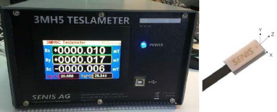
SENIS Low-Noise Teslameter 3MH5 and Hall probe C.
The PT2025 NMR Teslameter [14] is a gold standard calibration tool with the characteristics of rapid, automatic, and high-precision measurement. Based on the NMR effect, it achieves an absolute accuracy of 5 ppm and a resolution of 1e-3 Gs for measurements in the range of 0.43–137 T. The size of the probe model 1062 is 16.5 mm × 12.5 mm × 230 mm, as shown in Fig. 2, and is used for radial and axial magnetic fields.
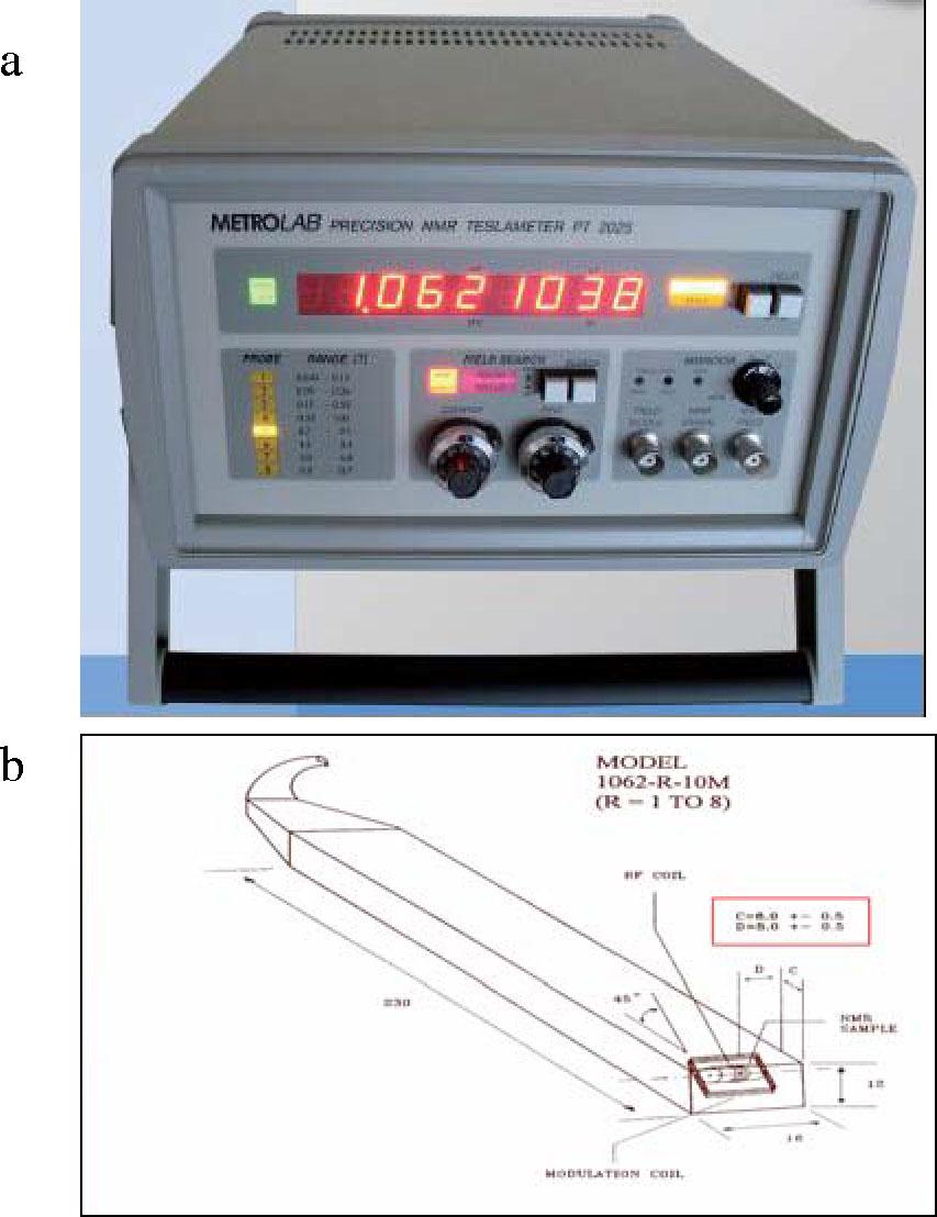
Metrolab PT2025 NMR Teslameter (a) and probe model 1062 (b).
In precision performance testing, temperature is a key factor in almost all physical properties. To reduce the effect of temperature on calibration, the calibration platform is placed in a 3 m × 3 m × 4 m temperature-stabilized chamber, and the temperature is controlled by a T224-31Eo heating ventilation air conditioning. The key specifications of the room are relative humidity with an accuracy of ±0.3% and temperature accuracy of ±0.2°C, with a temperature range of 7–60°C. The radiative heat load of the calibration magnet is estimated to be below 4000 BTU/h. Therefore, it has little effect on the temperature around the probe [15].
In addition, a thermoelectric semiconductor cooler is installed on the Hall probe, which can adjust different temperatures by using the Peltier effect principle of semiconductor materials. The temperature factor is calculated by calibrating the probe at three different temperatures to ensure accurate measurements at any temperature.
According to the calibration principle, the design of the calibration magnetic pole has become an urgent problem to be solved.
The SENIS Hall probe is calibrated by NMR probes no. 6 and no. 7, while NMR probe no. 7 allows a magnetic field uniformity of 160 ppm/cm. The uniformity of the magnetic field is a key factor in calibration work. To ensure the accuracy of calibration, the effective sensitive area of the NMR probe and Hall probe need to be within a uniform magnetic field. Therefore, the calibration magnetic pole needs to be designed according to the requirements of a uniform field. Based on the technical parameters of NMR and Hall probes, the effective sensitive area size of the NMR probe is Φ 4 mm × 4.5 mm, and the effective sensitive area size of Hall probe is 0.15 mm × 0.01 mm × 0.15 mm. Therefore, considering the aforementioned sensitive areas, it is preliminarily determined that the uniform space is a cylindrical area with a diameter of 10 mm and a height of 16 mm.
It is preliminarily determined to adopt cylindrical magnetic poles with diameters of 200 mm, 250 mm, and 300 mm respectively. The Tosca software is used to simulate the magnetic induction intensity value B and the uniformity value at the center point of the calibration magnetic field. The simulation model is shown in Fig. 3, and the simulation results are shown in Fig. 4. The red solid line represents the magnetic field uniformity value of the calibration space, and the blue dotted line represents the magnetic induction intensity value B at the center point. When the energizing current of a single turn coil for the superconducting coil is 160 A, the value of magnetic induction intensity B at the center point is close to 5 T. As the diameter of the calibration magnetic pole increases, the magnetic induction intensity B at the center point decreases, while the uniformity of magnetic field in the uniform space increases.
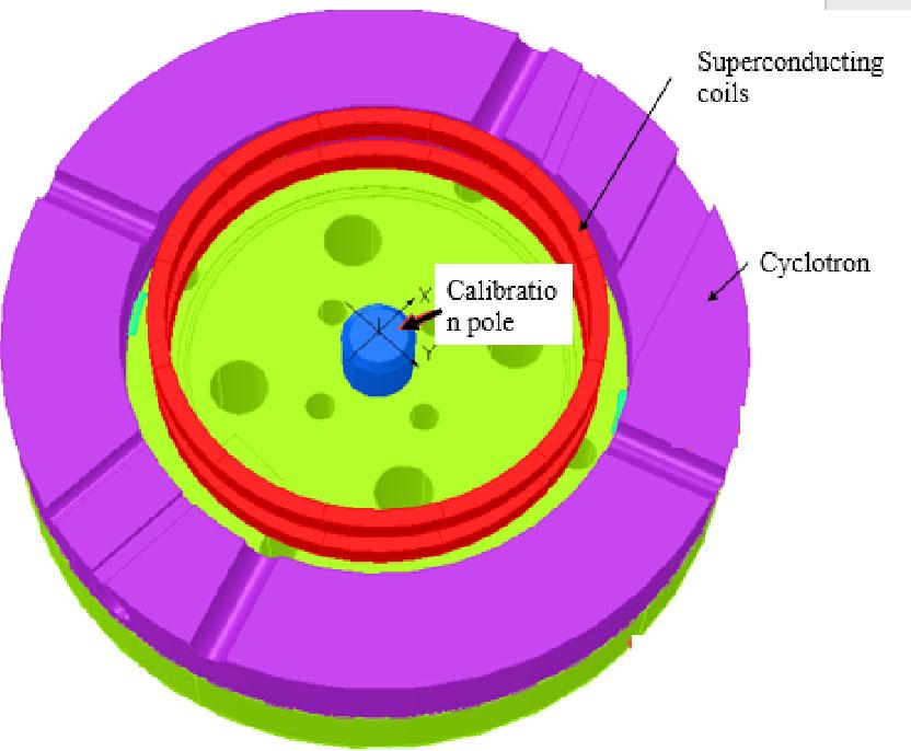
Simulation model of the magnetic calibration pole.
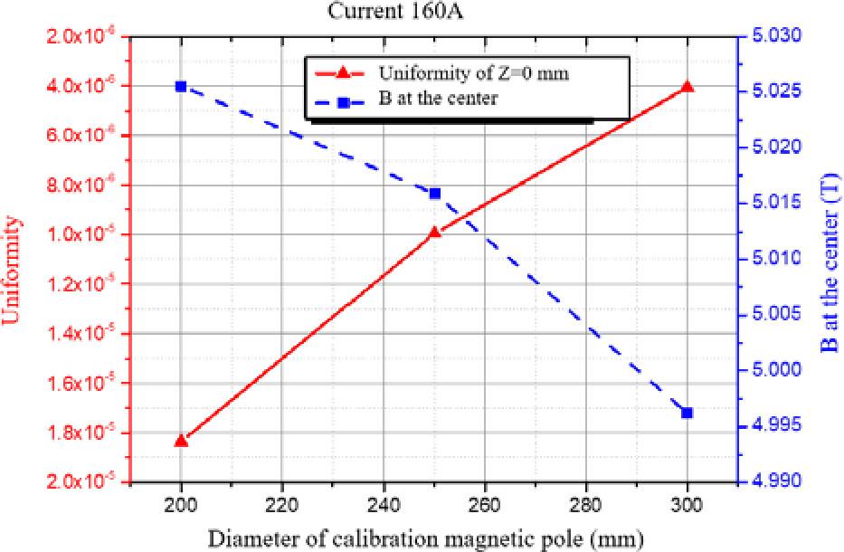
Calibration pole design analysis.
After comprehensive consideration, a radius of 250 mm is determined as the ideal size for calibrating the magnetic pole. The magnetic induction intensity is 5.016 T and the uniformity is 1e-5/cm, which is 10 ppm/cm, meeting the requirements of <160 ppm/cm. The magnetic field distribution of the uniform field space required for calibration is presented in Fig. 5.
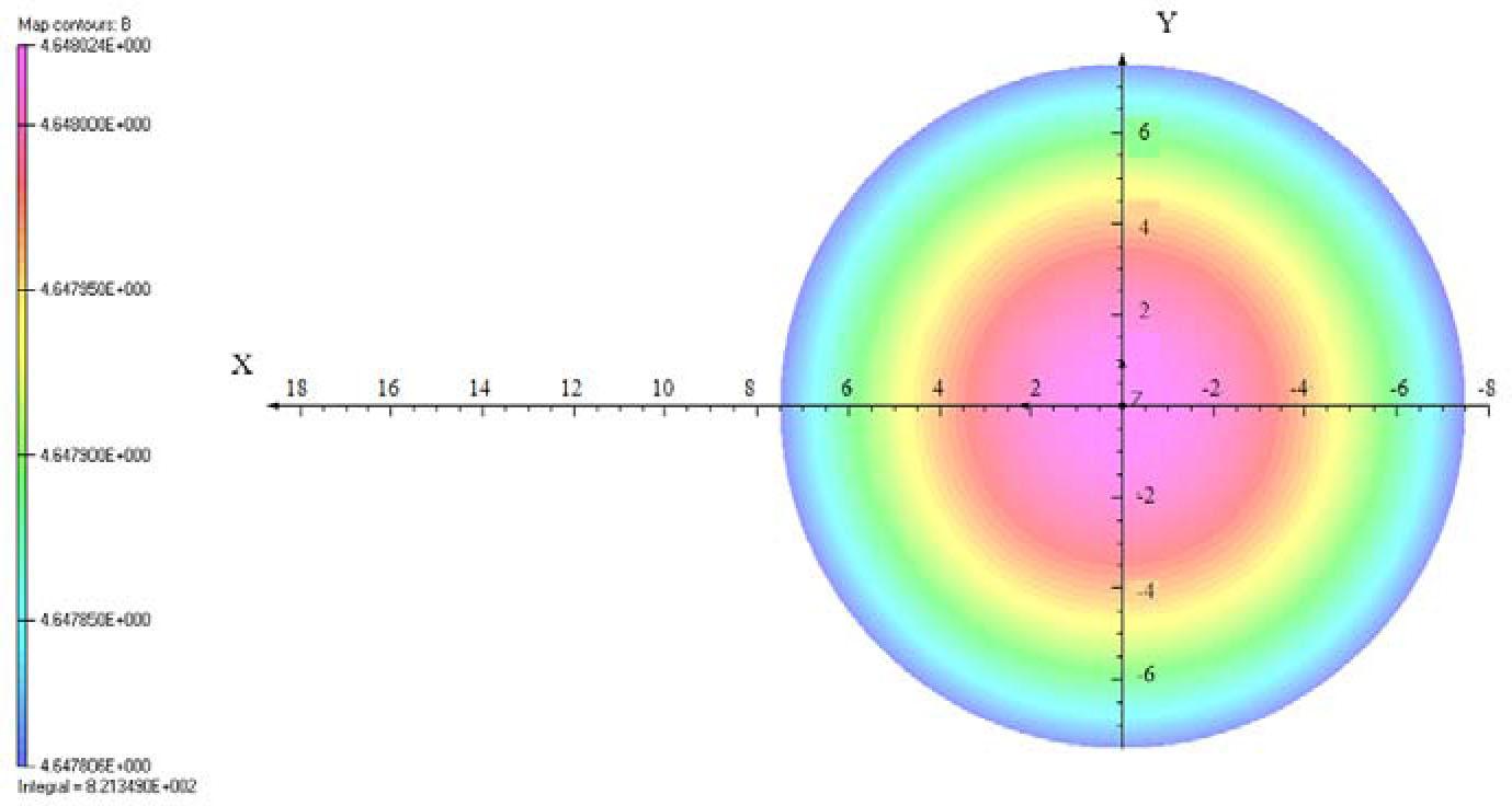
Schematic diagram of magnetic field distribution of calibration poles.
After completing the design and installation of calibration tooling, Fig. 6 shows an exploded view of the calibration tool. The slot on the tooling base plate is used to place two NMR probes no. 6 and no. 7. The Hall probe is situated in a groove on an aluminum support block and fixed by pressing it with a flat plate. The thermoelectric semiconductor cooler is pasted on the Hall probe and needs to be fully bonded to ensure uniform temperature conduction. This tooling design can ensure a close fit between the NMR and Hall probes. No. 6 and no. 7 1062 series NMR probes and 2 SENIS Hall probes are installed on the tooling fixture, respectively.
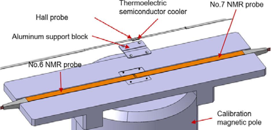
Decomposition diagram of calibration tooling model.
The assembled tooling is placed into the uniform field at the center of the calibration pole of SC200 superconducting cyclotron. The installation of the calibration tooling is shown in Fig. 7.
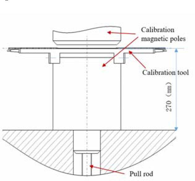
Installation diagram of calibration tool in cyclotron.
Hall probe is sensitive to both the perpendicular magnetic field component B⊥and the parallel component B||. If the magnetic field vector is not exactly orthogonal to the Hall probe, an additional voltage of planar effect (UPHE) is added to the normal Hall voltage (UNH) due to the magnetic field component [16]:
The UNH and UPHE are calculated from Eq. (2); the equation that describes the UPHE may be written as [17]:
To eliminate the plane effect error, the positive and reverse position configurations need to be considered. The reverse position is obtained by rotating 180° around the orthogonal direction of the magnetic field. In the reverse position, the polarity of the magnetic field changes sign with the Hall voltage, but does not change the plane Hall voltage, since it is proportional to the square of the magnetic field. Therefore, the difference between the two voltages UPos and URev eliminates the plane effect as follows:
As shown in Fig. 8, the calibration experiment platform mainly includes the superconducting cyclotron, calibration magnetic poles, calibration tooling, thermoelectric semiconductor cooler, NMR probe, Hall probe, SENIS-3MH5 Teslameter, computer, PT2025 NMR Teslameter, and constant current source. The calibration tooling integrates two NMR probes, four Hall probes, and a thermoelectric semiconductor cooler, which are fixed on a calibration magnetic pole. This calibration magnetic pole is fixed on the cyclotron by the rod through the central hole of the ion source. The assembled calibration tooling and calibration magnetic poles are then placed into the homogeneous field of the superconducting cyclotron at the pole center.
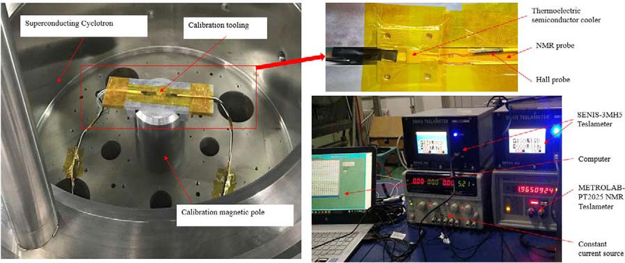
Experimental platform and calibration system.
In the process of measuring the magnetic field with a Hall probe, the temperature is an important factor. In this calibration experiment, a thermoelectric semiconductor cooler is used to achieve different temperatures, and the principle of Peltier effect of semiconductor materials is used to adjust the temperature. The Hall probe needs to be calibrated at three temperature ranges of 20°C, 26°C, and 32°C, and the temperature factor is calculated to ensure that the Hall probe can realize accurate measurement at any temperature.
The construction of the thermoelectric semiconductor cooler temperature test-bed is shown in Fig. 9. It is mainly composed of a constant current source, SENIS-3MH5 Teslameter, calibration tooling, and a computer. In this case the NMR probe is only used as the support of Hall probe and does not need to be connected to Metrolab-PT2025.
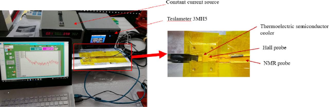
Temperature test bench.
By adjusting the output current value of the constant current source, the relationship between the energizing current and the probe temperature is obtained, as shown in Fig. 10. During the temperature experiment, the temperature stability was good and no fluctuations were observed. The heating and cooling rates of the Hall probe are different. It takes 55 s for the temperature to rise from 20°C to 32°C, while it takes 40 s to drop from 32°C to 20°C.
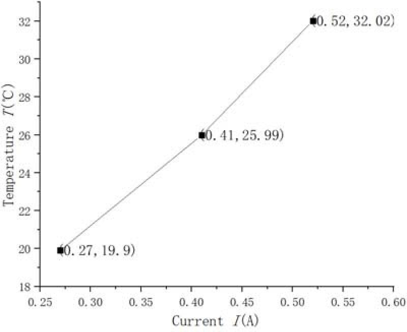
Relationship between the energizing current and the probe temperature.
First, the no. 6 probe cable should be connected to the PT2025 Teslameter and a 130-2D Hall probe should be connected to Teslameter 3MH5. Then, the debugging tools should be opened, the device panel function should be verified through button operation, and the communication function of the device should be verified through the serial debugging. The calibration module of PT2025 Teslameter is integrated in the SENIS software. The communication is completed by connecting the DB9 cable to the Com1 port of the computer.
Finally, the Teslameter 3MH5 equipment control should be adjusted. In this calibration process, the voltage is selected as output. At the same time, the magnetic induction intensity components of Bx, By, and Bz values are displayed in real-time curve form.
The calibration process is determined based on the calibration principle. The Hall probe, NMR probe, and thermoelectric semiconductor cooler were integrated on the calibration tooling and then placed in a homogeneous field of the accelerator. Start by connecting the cable and debug the interface. The calibration temperature is adjusted to 20°C. The initial calibration point is 2 T and the step size is 300 Gs. In addition, the step size and the number of calibration points can be adjusted based on the test results. At 20°C, the relationship between the excitation current I and the required magnetic induction intensity B is as shown in Fig. 11. For the same excitation current value I, the theoretical magnetic induction intensity is B1, and the actual magnetic induction intensity is B2. After analysis and calculation, the error between them is acceptable.
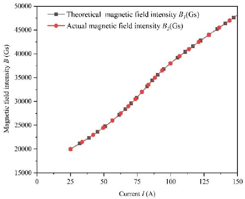
Relationship between the excitation current I and the required calibration magnetic induction intensity B.
After the measurement values are stable, the signal light of the PT2025 equipment will light up. The measurement values of each calibration point are recorded through the “Measure” and “Add” buttons in the program. The PT2025 Teslameter is used to read the precise magnetic induction intensity, and the Teslameter 3MH5 is used to measure the voltage and temperature values. When the magnetic induction intensity reaches 3.2 T, the no. 7 NMR probe is connected to the PT2025 instrument.
Then, the temperature is set to 26°C and 32°C through thermoelectric semiconductor cooler. The above steps are repeated to obtain the calibration relationship and data file of the 130-2D Hall probe. The calibration data is re-imported into the device and the calibration for the 130-2D Hall probe is completed within the magnetic field range of 2–5 T.
After all calibration points are measured, the Hall probe is placed in the zero-field cavity for zero calibration adjustment. The calibration process flowchart is shown in Fig. 12.
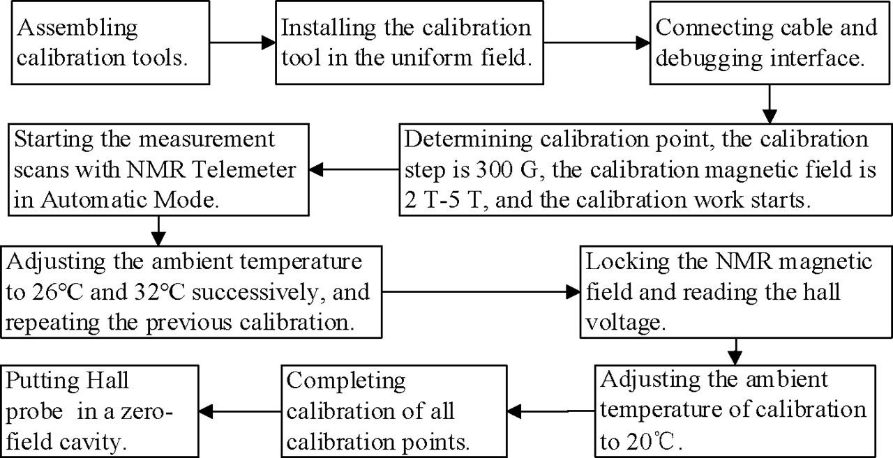
Flow chart of Hall probe calibration process.
In the magnetic field calibration environment, the magnetic induction intensity values are read by the SENIS calibration software, and the curves of Bx, By, Bz, and temperature TH values are plotted in real-time, as shown in Fig. 13.
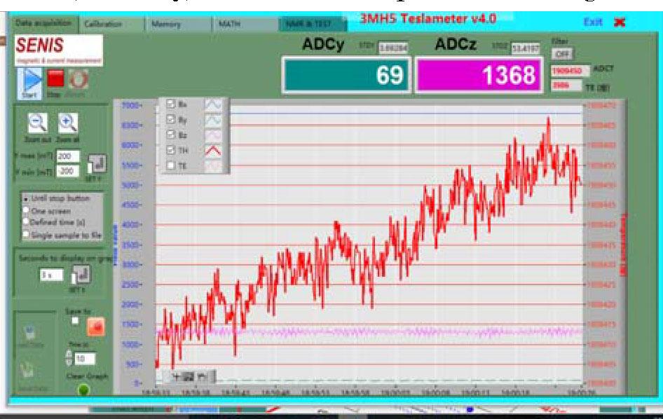
Drawing curves of magnetic induction intensity and temperature values.
On the program interface, the calibration axis Y of the Hall probe is selected, and the magnetic induction intensity B is selected by PT2025 Tesla instrument. The SENIS is used to measure the voltage U and Hall probe temperature T, and the current value is saved by pressing the “Add” button. The data are collected, a calibration table is created, and it is saved as an XLS format file for data processing and analysis, as shown in Fig. 14.
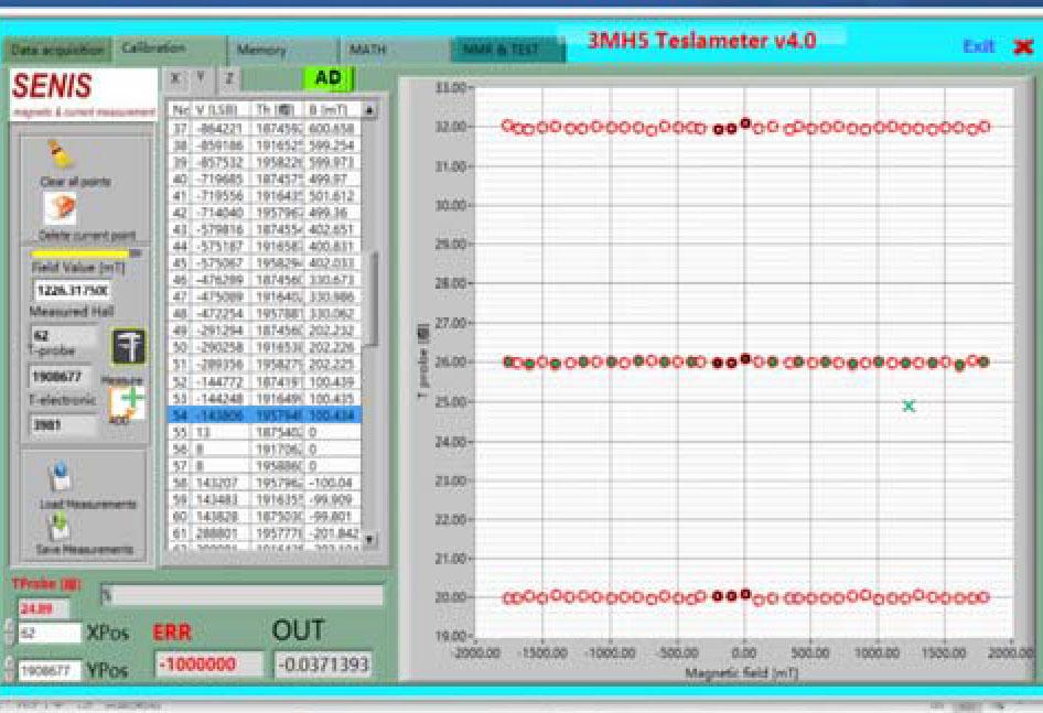
Calibration point value reading and calibration table creation.
The calibration table is saved and updated. The measurement data are sent to the 3MH5, and the calibration data are sent to the probe. The calibration of Hall probe can be completed on the assigned axis.
As shown in Fig. 15, after completing collection of the calibration data, the corresponding calibration factor, namely, the relationship between magnetic induction intensity B and voltage U and temperature TH, is obtained through fitting calculation using the SENIS built-in algorithm. In this way, each Hall probe corresponds to a fixed calibration factor. After resetting the device, the calibration table is refreshed by Tesla 3MH5, and the new calibration factor can directly call up. Eventually, the magnetic field could be measured through the Hall probe directly.
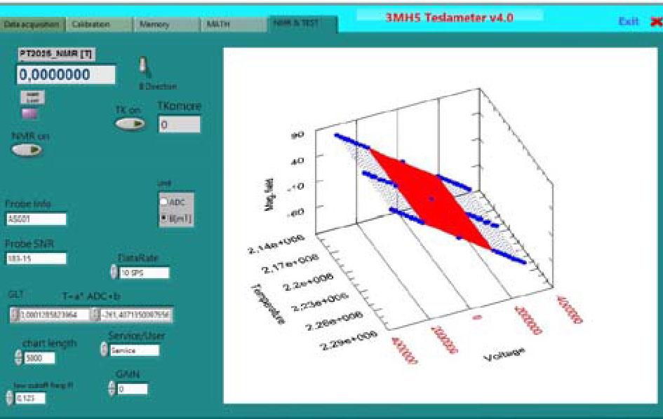
Calibration data fitting in program.
To cross-verify the authenticity and reliability of calibration data, the polynomial fitting method is used to process the data. According to the magnetic induction intensity B, output voltage U, and temperature T recorded by the SENIS software, the relationship between magnetic induction intensity and output voltage B–U, and the magnetic induction intensity and temperature B–T were derived. Taking the calibration data of 130-2D probe as an example, the specific derivation process is as follows.
To achieve the relationship of magnetic induction intensity and voltage B–U the three temperatures were calculated at T1 = 20°C, T2 = 26°C and T3 = 32°C, respectively. The B–U curve is fitted by cubic polynomial method, that is, Bpol1 = a0 + a1 × U + a2 × U2 + a3 × U3, where a0, a1, a2 and a3 are fitting curve coefficients. The curve fitting results are shown in Fig. 16 and the polynomial formula is shown in Table 2.
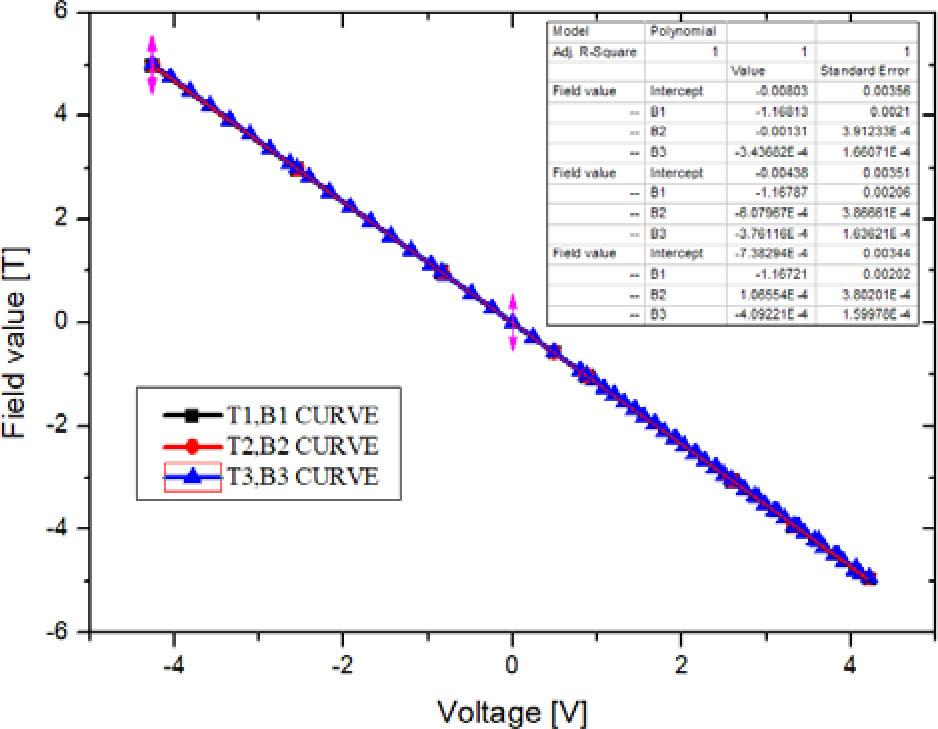
Fitting curves of polynomial Bpol1.
Fitting results of polynomial Bpol1
| Temperature, T | Polynomial fitting Bpol1 formula |
|---|---|
| T1 = 20°C | Bpol1 = −0.0080 − 1.1681*U − 0.0013*U2 − 3.4368e-4*U3 |
| T2 = 26°C | Bpol1 = −0.0044 − 1.1681*U − 6.080e-4*U2 − 3.7612e-4*U3 |
| T3 = 32°C | Bpol1 = −7.3829e-4 − 1.1672*U + 1.066e-4*U2 − 4.0922e-4*U3 |
To calculate the deviation ΔB1 = B–Bpol1 and perform linear fitting of the ΔB1–U relationship, ΔB1 = b0 + b1 × U, where b0 and b1 are the fitting curve coefficients. Polynomial fitting Bpol2 = Bpol1 + ΔB1 = (a0 + b0) + (a1 + b1) × U + a2 × U2 + a3 × U3, and the Bpol2 sequence group is calculated.
Calculate the deviation ΔB2 = B–Bpol2 and make the scatter diagram of ΔB2. The scatter diagram of ΔB2 is shown in Fig. 17. The distribution range is between −0.1 Gs and 0.1 Gs, which is less than ±1 Gs, so the B–U calibration data are acceptable.
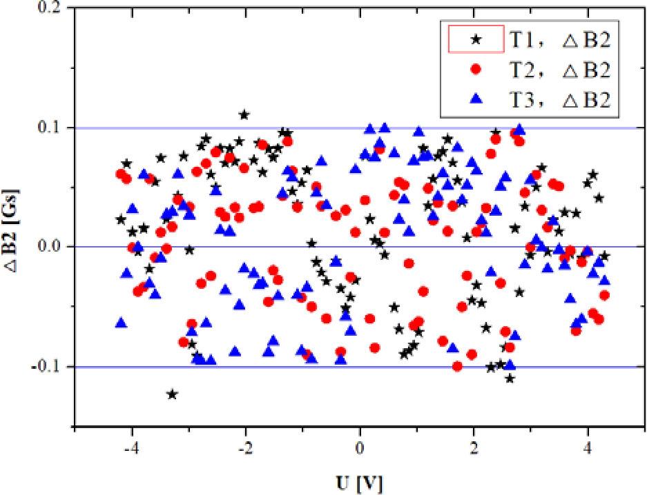
Scatter diagram of ΔB2.
As shown in Fig. 18, the relative errors of the three-axes calibration are <0.01%. The results indicate that the calibration results are reasonable and reliable.
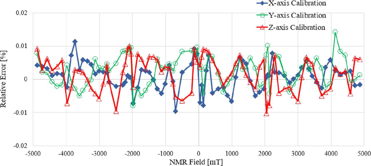
Calibration relative error curves.
This research mainly studies the key technology of SENIS Hall probe calibration. First, the SENIS Hall probe was calibrated using the Swiss PT2025 NMR and 1062 probe, in which the superconducting magnets and calibrated magnetic poles were used to provide a magnetic field environment. The calibration magnetic poles and calibration tools were designed, the calibration experimental platforms were built, the calibration processes were developed, and the calibration data were analyzed. Then, to cross-verify the reliability of calibration data, the polynomial fitting method is adopted to calculate the deviation and the distribution range, which is between −0.1 Gs and 0.1 Gs. Finally, through calibration, the measurement accuracy of Hall probe in the range of 2–5 T was improved to 1e-4, which can accurately measure the magnetic field distribution in the superconducting cyclotron, providing important data for magnetic field filling and particle beam dynamics calculations. In summary, it provides a strong and stable magnetic field environment for the normal operation of superconducting cyclotron for cancer treatment.