
The construction of a free-electron laser (FEL) is planned at the National Centre for Nuclear Research in Otwock, making it the first facility of its kind in Poland and Eastern Europe [1, 2]. The process involves the construction of an electron accelerator, with the goal of eventually accelerating electrons to energies ranging from 72 MeV to 280 MeV. Radiation safety considerations require the accelerator to be shielded in such a way that the radiation level outside the shielding does not exceed 0.15 μSv/h [3,4,5]. It is assumed that there will be beam losses in the device at a level of 1 W/m. These lost electrons will impact the side walls of the beamline and the devices surrounding the beamline, serving as a source of secondary radiation, mainly photon and neutron radiations. This paper presents a model designed to replicate the assumed beam losses. This model will be used in further Monte Carlo calculations of the bunker shielding using the FLUKA code in 2021 version [6, 7].
The spatial and energy distribution of electrons lost from the beam with a maximum energy of 187 MeV or 280 MeV were reconstructed using the following procedure. The location of electron loss is randomly selected along the entire length of the planned beamline, and the corresponding energy is assigned based on the randomly selected coordinate Z, as shown in Fig. 1. The maximum assumed energy of 72 MeV, 187 MeV or 280 MeV is reached for a Z coordinate ≥10.9 m, ≥27.8 m or ≥41.3 m, respectively. It has been planned that depending on the energy, the beam will be transported along different trajectories. The two highest energies are to be released straight along trajectory (a), while the lowest energy, after deviating by 2.5 m towards S, will be released along trajectory (b), starting at Z coordinate equal to 14.5 m, as shown in Fig. 2. The accelerator's construction plans foresee that at a distance of 63.4 m in a straight line from the electron beam's photocathode, the beam will be diverted towards N, where experiments utilizing inverse Compton scattering are to be conducted, as well as for directing it to the beam dump. The diversion of the beam in the source model was formally accomplished so that for a randomly selected Z coordinate >63.4 m, a change in the assignment of position coordinates and beam direction occurred, such that the Z and Y coordinates change appropriately, ensuring the rotation of generated electron losses towards N, in accordance with the construction requirements. Looking at Fig. 2 and 3, it can be seen that the total length of the designed trajectory (a) of beam losses for energies of 187 MeV and 280 MeV will be 80.8 m, while the designed trajectory (b) of beam losses for energy of 72 MeV will be longer by 2.5 m, totaling 83.3 m.
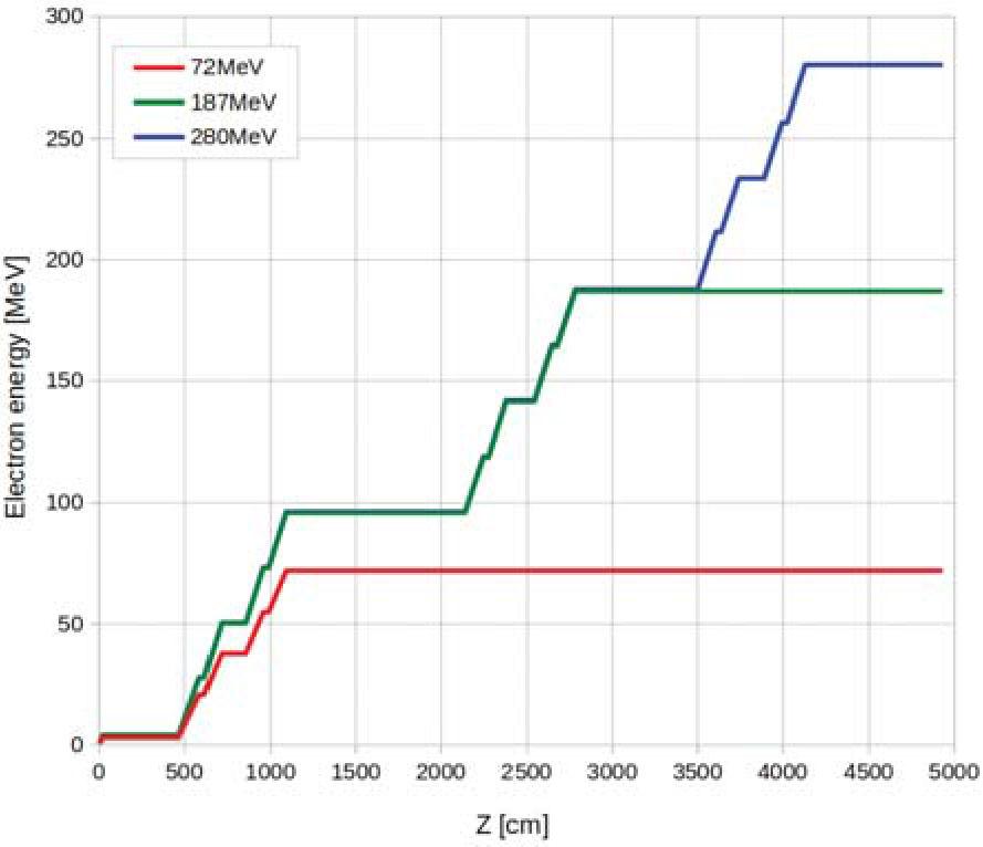
Planned electron beam energy dependence as a function of Z coordinate, along a superconducting linear PolFEL accelerator.
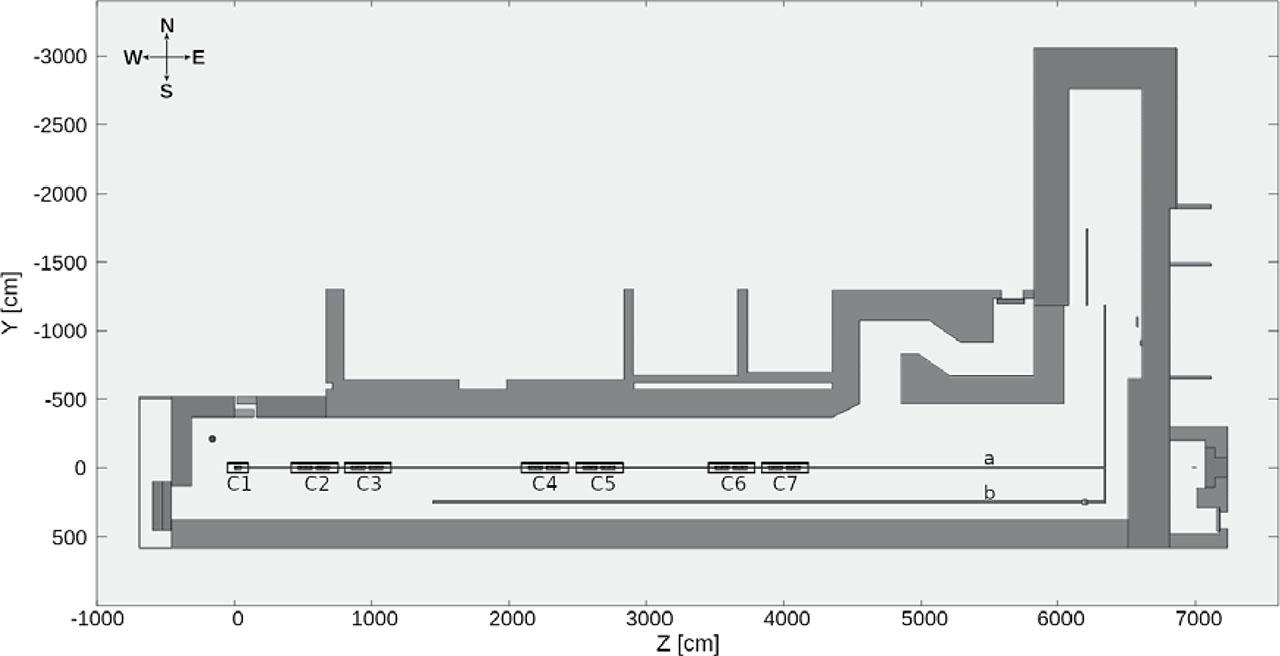
Model of a linear electron accelerator for the planned energies of 72 MeV, 187 MeV and 280 MeV, together with the planned seven superconducting accelerating cryomodules (C1–C7) required to achieve the maximum assumed electron beam energy of 280 MeV. One can see the two trajectories foreseen for the 187 MeV and 280 MeV beams (a) and for the 72 MeV beam (b). The scheme shows one of the planned versions of the shield walls, based in part on the walls of another already existing bunker. In the upper left corner, there is an indication of the world directions in relation to which the planned bunker will be oriented.
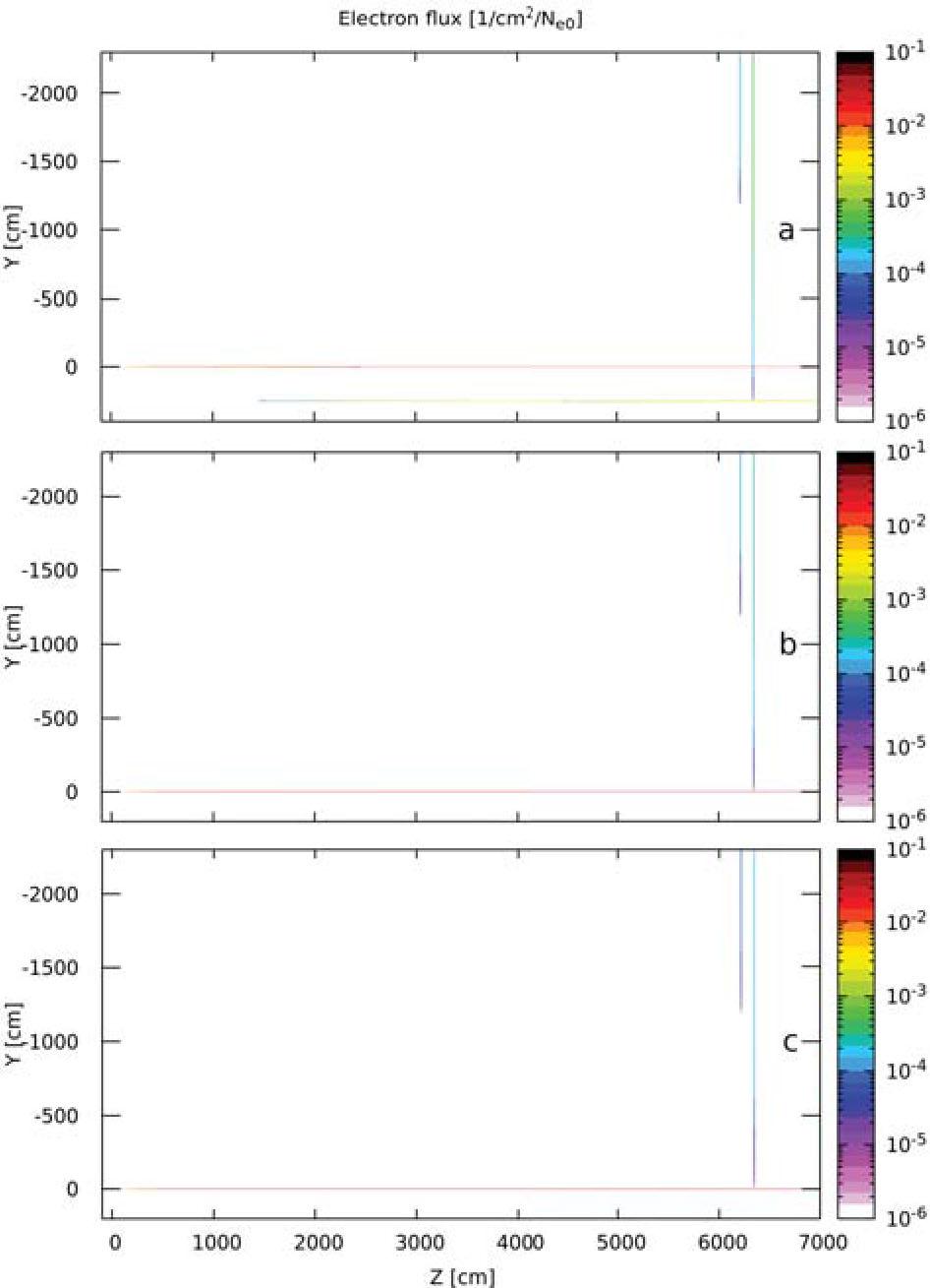
Spatial distribution of electron fluxes lost from the main beam and transported in vacuum for 72 MeV (a), 187 MeV (b) and 280 MeV (c). Horizontal view, parallel to the beam axis. All Monte Carlo calculation results presented in this paper are normalized to a single primary beam electron.
Assuming a minimum energy of 0.5 MeV for the 72 MeV beam and 0.7 MeV for the 187 MeV and 280 MeV beams for lost electrons was done to prevent excessively high fluxes of low-energy electrons, which would not make a substantial contribution to radiation calculations.
It was assumed that the source of lost electrons for radiation calculations is a cylinder with a radius of 3.9 cm, corresponding to the inner surface of the pipes through which electron beams were distributed. A uniform angular distribution of lost electrons around the beam axis and an angular divergence of 1 mrad relative to the beam axis were assumed.
The geometry model of the linear electron accelerator, superconducting accelerating cryomodules and shielding walls are shown in Fig. 2. From a radiological perspective, the modeled trajectory of the beamlines is practically consistent with the designed layout.
The fundamental physical assumption is the acceptance of constant real beam losses over the entire length of the studied accelerator at a level of 1 W/m, without specifying the causes of these losses. Consequently, this enforces a constant electron flux for areas where electrons are not accelerated and modifies the probability distribution of emitted lost electrons to a 1/E-type dependence for regions where electrons are linearly accelerated.
Further calculations were made assuming a real beam loss of 1 W/m. Then the total flux of electrons wasted along the whole length of the beam pipe will be the sum of the electron fluxes in the regions with acceleration of electrons and in the regions without acceleration.
The electron fluxes in areas without acceleration can be expressed as:
In the case of regions with linear energy increments as a function of the position, the 1/E dependence of the lost electron flux is still valid. However, the energy dependence as a function of position can then be expressed in terms of the directional equation of a straight line, which in the j-th acceleration region can be written as:
The resulting electron fluxes must be added up for all regions of acceleration to obtain the total electron flux from the areas where electron acceleration occurs.
Finally, the total flux of lost electrons can be expressed as:
For the sake of order in these calculations, all energies are assumed to be expressed in GeV, all coordinates in m, aj coefficients in GeV/m and bj coefficients in GeV. To ensure energy loss of 1 W/m, it is necessary to set the constant at 6.2415 × 10⁹ e/s·GeV/m.
Based on the above considerations, it was calculated that the total flux of lost electrons ensuring a beam loss of 1 W/m is 1.7991 × 10¹³ e/s, 1.1537 × 10¹³ e/s and 1.1012 × 10¹³ e/s for 72 MeV, 187 MeV and 280 MeV beam energies, respectively. These are the electron numbers that will be used for further Monte Carlo shielding calculations. A comparison of the electron fluxes lost in the areas without and with acceleration is shown in Table 1.
Summary of calculated electron fluxes lost from a cylinder with a radius of 3.9 cm to provide a beam loss of 1 W/m. This radius corresponds to the radius of the designed beam pipe
| Electron energy (MeV) | Φnoacc (e/s) | Φacc (e/s) | Φ (e/s) |
|---|---|---|---|
| 72 | 1.5840 × 10¹³ | 2.152 × 10¹² | 1.7991 × 10¹³ |
| 187 | 9.729 × 10¹² | 1.808 × 10¹² | 1.1537 × 10¹³ |
| 280 | 9.097 × 10¹² | 1.915 × 10¹² | 1.1012 × 10¹³ |
Using the FLUKA code in 2021 version [6, 7], preliminary calculations of the spatial and energy distribution of electrons lost from the beam pipe and the transport of these electrons in vacuum were performed.
The energy spectra of the lost electrons are presented in Fig. 4. It can be observed that the energy dependence of the 1/E-type electron flux intensity is reproduced. Small deviations from this dependence are associated with slightly varying effective accelerating potentials assumed in specific cryomodules within the beam dynamics calculations. It is also noticeable that the spectra exhibit a significant increase in electron flux intensity at specific energies. These characteristic energies align with the assumed energy distributions of lost electrons shown in Fig. 2, corresponding to constant energies in regions without acceleration. The height of the energy spectrum bin, reflecting the magnitude of such lost electron fluxes, depends on the length of the non-accelerating regions, illustrated in Fig. 1 as areas beyond the accelerating cryomodules.
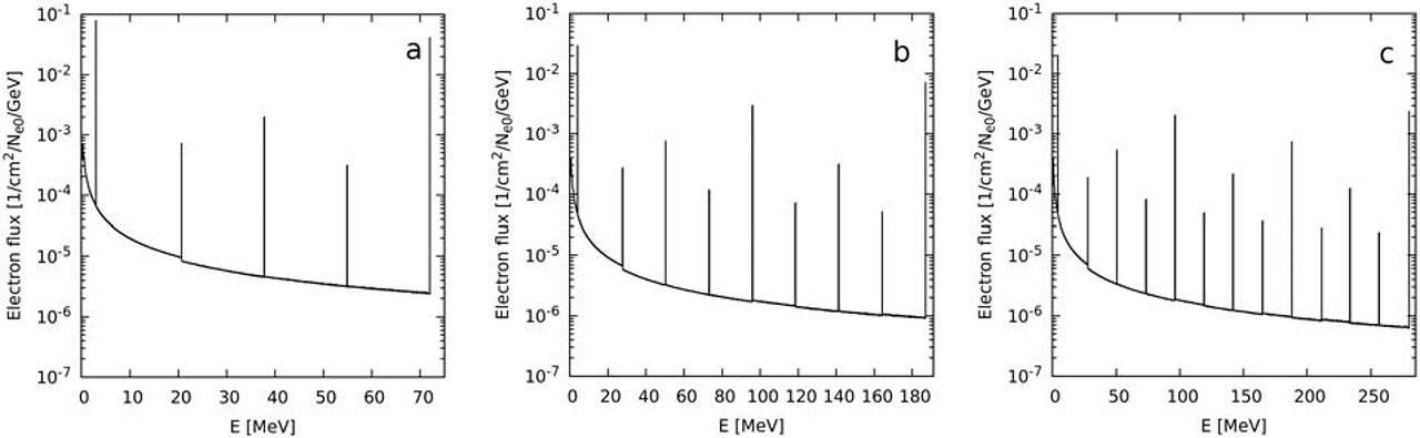
Calculated spectra of electrons incident on the inner surface of the beam pipe for 72 MeV (a), 187 MeV (b) and 280 MeV (c).
The spatial distributions of lost electrons along the entire electron path are shown in Fig. 3. Beam losses are visible in the branch of the 72 MeV beamline at Y = 2.5 m, losses after bending the beam trajectory by 90° at Z = 63.4 m, and in the subsequent branch at Z = 62.1 m. A magnified view illustrating the spatial distribution of beam losses along the main beam axis with varying Z coordinates is presented in Fig. 5, and along the branch axis for 72 MeV in Fig. 6. A uniform spatial angular distribution around the beam axis is shown in Figs. 7 and 8. Minor differences in spatial distributions are apparent in these figures, arising from the assumed relationship between the energy of lost electrons and their loss locations in this study.
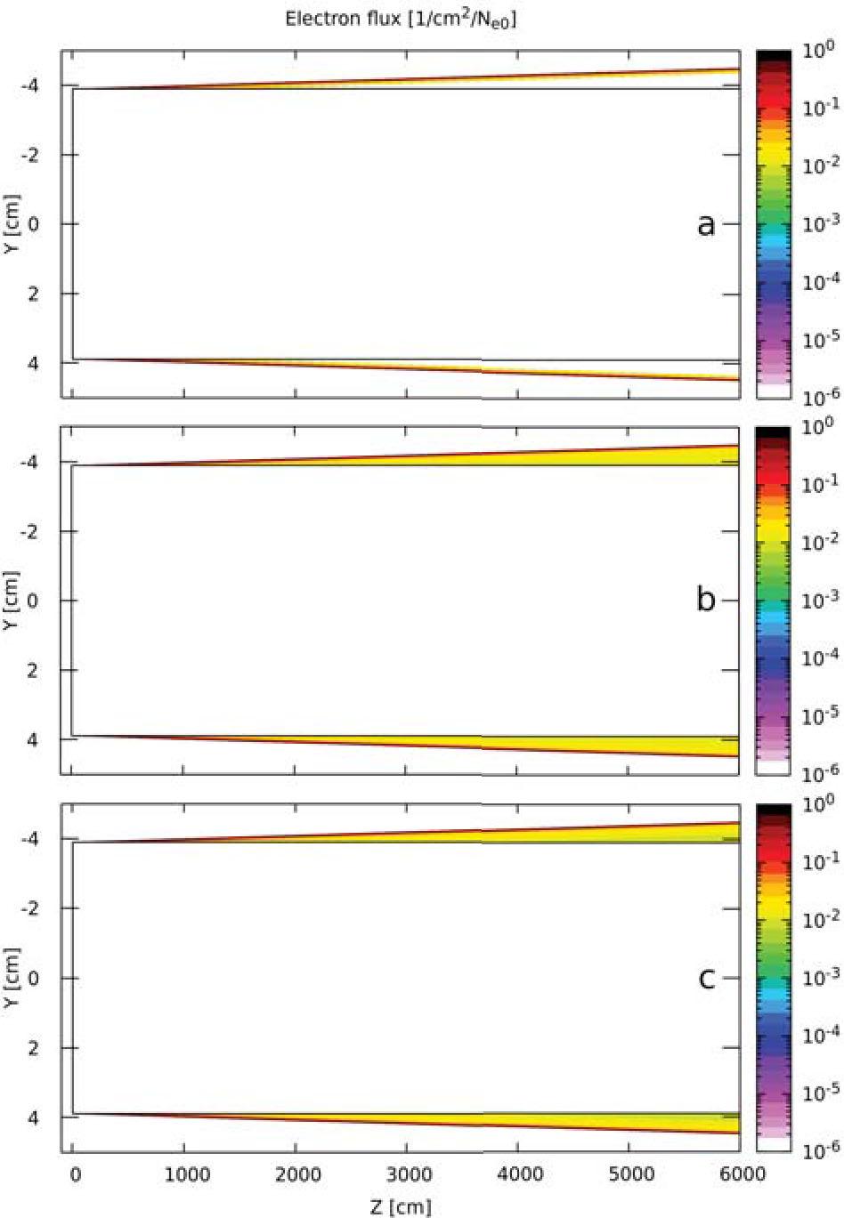
Spatial distribution of electron fluxes lost from the main beam and transported in vacuum for 72 MeV (a), 187 MeV (b) and 280 MeV (c). Magnification along the beam pipe with cryomodules. The limits of a cylinder of radius 3.9 cm are visible. The vertical and horizontal axis scales are different.
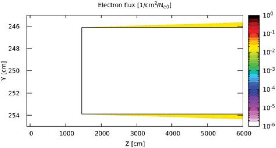
Magnification of spatial distribution of electron flux lost from the branch for 72 MeV and transported in vacuum. The limits of a cylinder of radius 3.9 cm are visible. The vertical and horizontal axis scales are different.
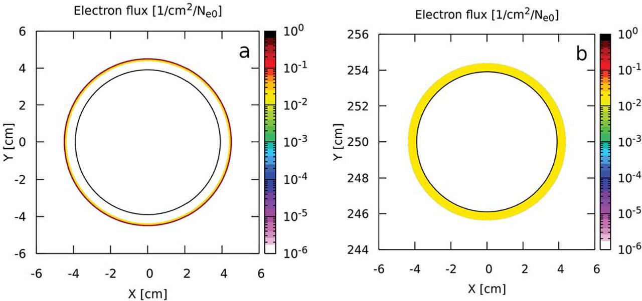
Magnification of the spatial distribution of electron flux for 72 MeV, (a) for the main beam pipe and (b) for the beam pipe shifted by 2.5 m. The limits of a cylinder of radius 3.9 cm are visible. View in the plane perpendicular to the beam axis for Z coordinate = 62 m.
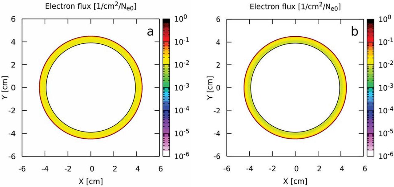
Magnification of the spatial distribution of electron flux for 187 MeV (a) and for 280 MeV (b). The limits of a cylinder of radius 3.9 cm are visible. View in the plane perpendicular to the beam axis for Z coordinate = 62 m.
A consistent model for the source of electrons lost along the entire path of the electron beam has been successfully developed. This model is based on simple assumptions and dependencies. As a result of its practical application in Monte Carlo calculations, non-trivial energy, momentum and position distributions can be obtained. The source model described in this paper will be used as the basis for all further shielding calculations of the superconducting PolFEL linear accelerator.