
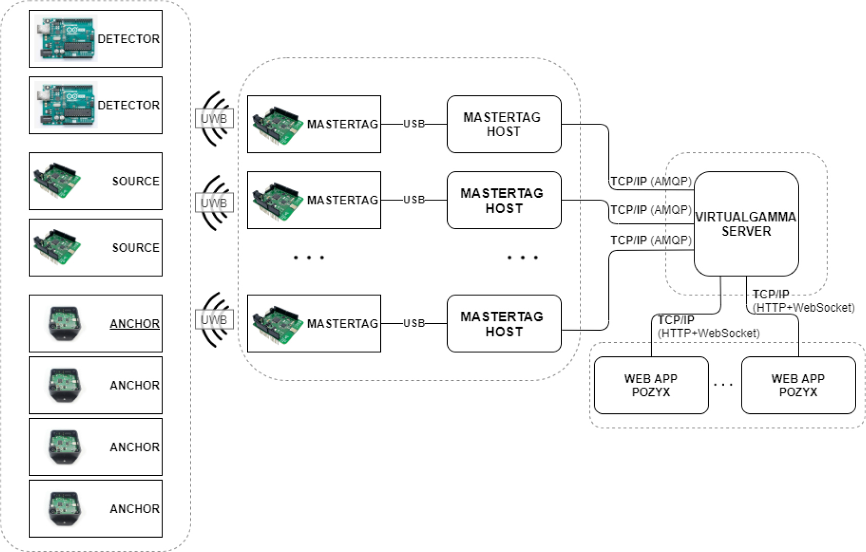
Fig. 1.
Virtual–virtual schematic diagram of the VRSS system.
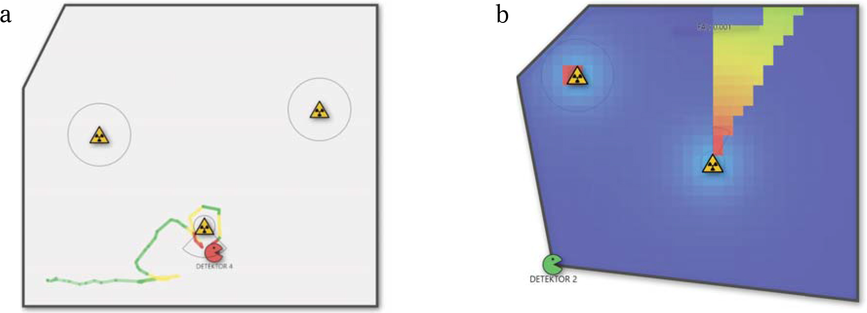
Fig. 2.
Personal route monitoring (a) and visualization of the dose rate map (b).
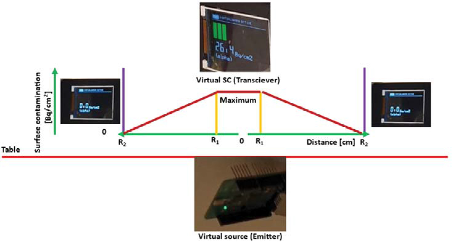
Fig. 3.
Operation of the virtual surface contamination meter.
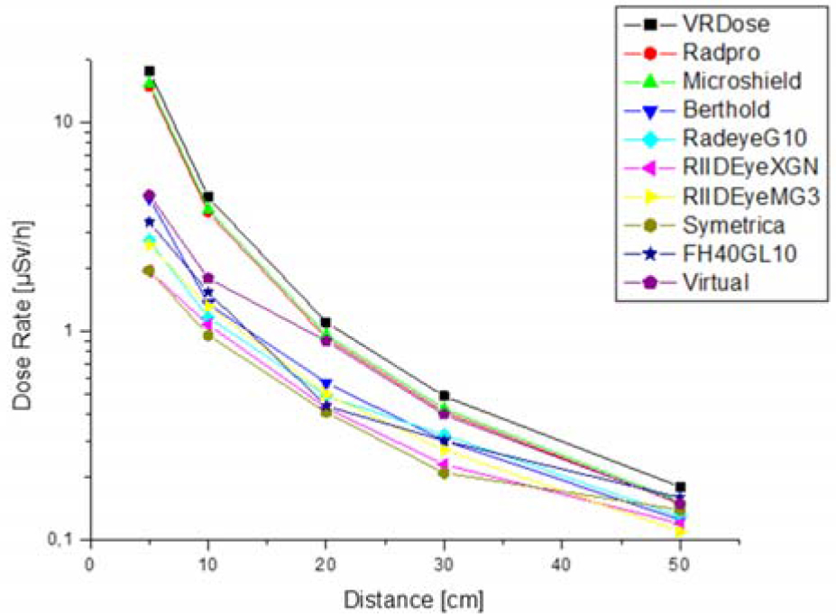
Fig. 4.
Comparison of dose rate measurements between different virtual codes, real instruments, and the VRSS. Calculation codes: VRdose (Halden), Rad Pro Calculator (Beytepe), MicroShield (Lynchburg). Instruments: Berthold UMo (Vienna), RadEye G-10 (Waltham), Ribeye X-GN, RIIDEye M-G3 (Waltham), Symetrica (Southampton), Thermo FH 40 G-L10 (Waltham), and Virtual dose rate meter (Budapest).
Table 1.
Surface contamination (SC) values after each decontamination process
| Virtual SC detector | SC (Bq/cm2) |
|---|---|
| Background radiation | 0.00 |
| Max. value at the center of the hot spot | 26.40 |
| Decontamination step 1 | 12.32 |
| Decontamination step 2 | 9.63 |
| Decontamination step 3 | 7.45 |
| Decontamination step 4 (all nonfixed contamination removed) | 7.45 |
| Covering the hot spot with foil | 0.00 |
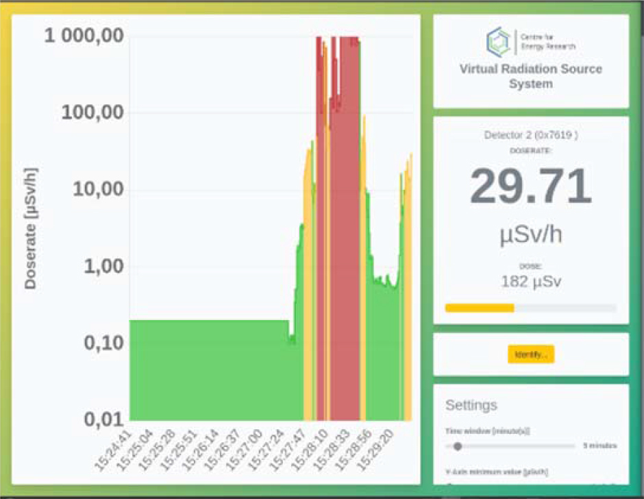
Fig. 5.
The online, real-time signal panel of the VRSS.