

Fig. 1.
The general scheme of the measurement system during the investigations.

Fig. 2.
General concept of signal conditioning module.
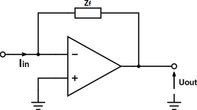
Fig. 3.
The transimpedance amplifier.
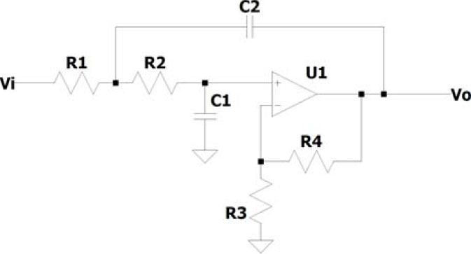
Fig. 4.
The low-pass filter circuit (Sallen–Key configuration) used in the design.
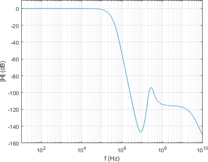
Fig. 5.
The Bode plot of the transimpedance of the complete signal conditioning circuit.
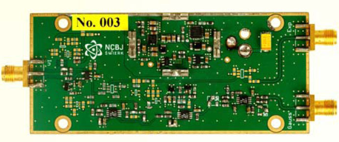
Fig. 6.
The photograph of the designed temperature proof device.
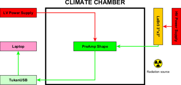
Fig. 7.
Experimental setup.
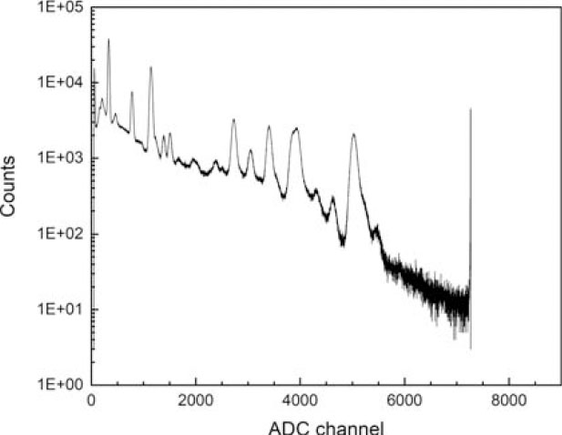
Fig. 8.
Eu-152 spectrum; temperature: 20°C, count rate: 30 kcps.
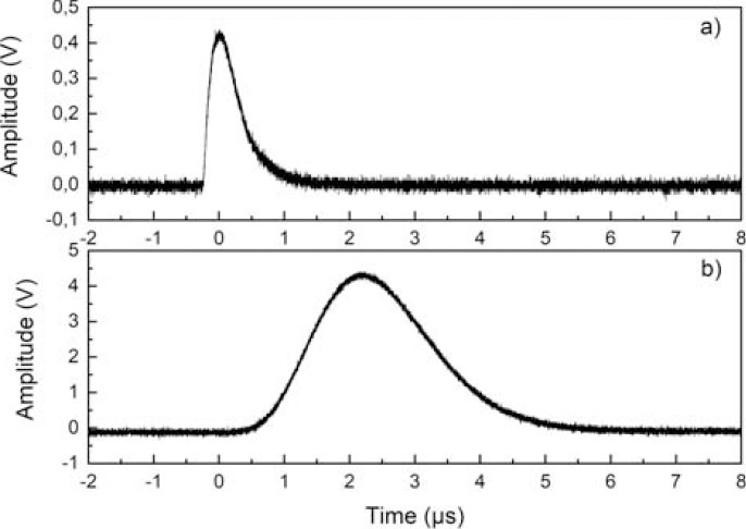
Fig. 9.
The shapes of the signals from charge preamplifier and from output of our module.
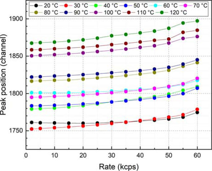
Fig. 10.
Dependence of the 511 keV (Na-22) peak position on the count rate.
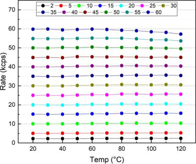
Fig. 11.
The dependence of count rate for different temperatures, for the Na-22 radiation source.
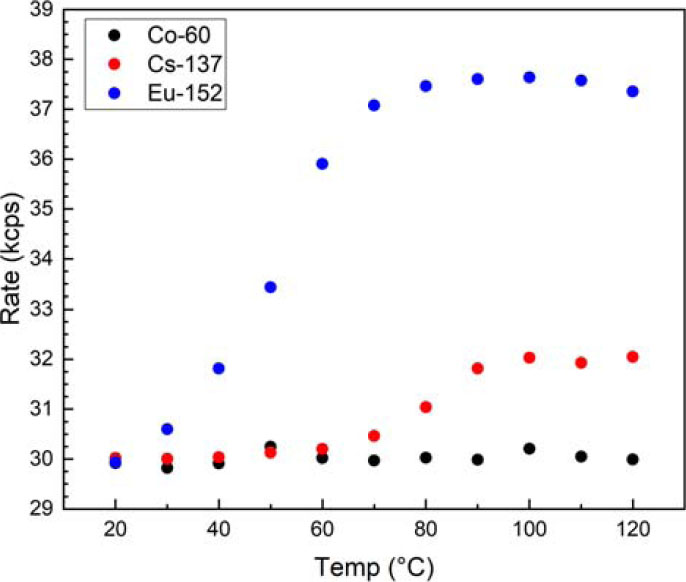
Fig. 12.
The dependence of count rate for different temperatures, for other radiation sources.
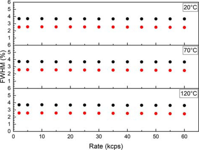
Fig. 13.
The energy resolution of two FEP from the Na-22 source (511 keV – black, 1275 keV – red), for different temperatures.