Fig. 1.
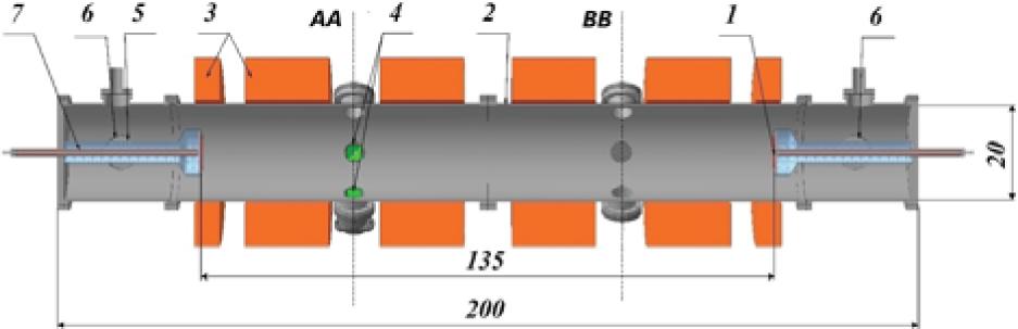
Fig. 2.
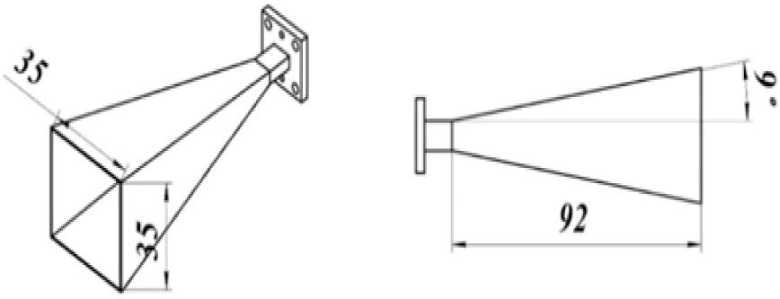
Fig. 3.
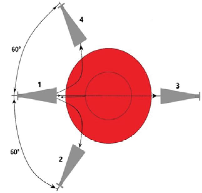
Fig. 4.
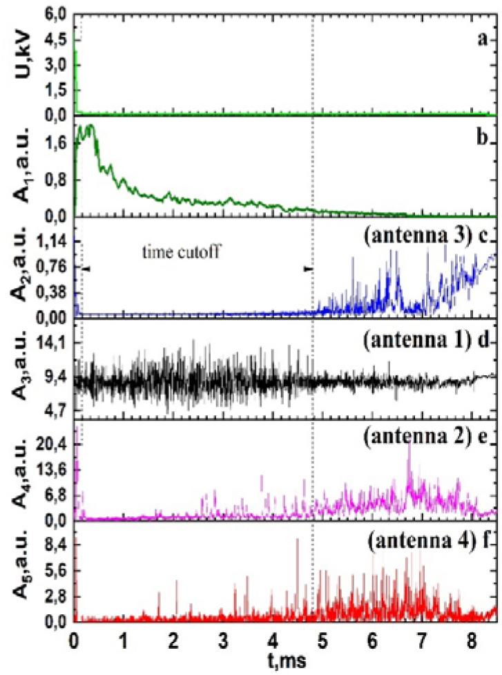
Fig. 5.
Fig. 6.
Fig. 7.

© 2023 Yurii P. Martseniuk, Yevhen V. Siusko, Yurii V. Kovtun, published by Institute of Nuclear Chemistry and Technology
This work is licensed under the Creative Commons Attribution-NonCommercial-NoDerivatives 4.0 License.