
1. Introduction
Streak cameras are indispensable diagnostic instruments for recording ultrafast optical phenomena because they can convert transient optical signals into spatially resolved electron images and simultaneously provide temporal and spatial information with ultrahigh precision. Owing to this unique capability, they have been widely used in high-energy-density physics, laser-driven fusion diagnostics, compressed ultrafast photography, and time-resolved optical imaging. In inertial confinement fusion (ICF) experiments, streak cameras are required to provide both high temporal resolution and high spatial fidelity over a sufficiently large field of view, enabling accurate measurements of implosion dynamics, radiation emission, shock propagation, and other rapidly evolving processes [1]–[4]. For such applications, a spatial resolution exceeding 10 lp/mm and a field of view larger than 17 mm are typically required to meet the demand for high-precision spatial-temporal diagnostics. In compressed ultrafast photography (CUP), the streak camera serves as the key temporal shearing device and must provide a large effective photocathode area, high spatiotemporal resolution, and sufficient luminance gain to support single-shot imaging of non-repetitive ultrafast events [5], [6]. In streak-tube imaging lidar (STIL), a large working area and high spatial resolution are essential for obtaining a wide azimuth field of view and accurate range-resolved three-dimensional imaging [7]–[10]. Therefore, developing streak tubes that simultaneously offer a large photocathode working area, high spatial resolution, and high temporal resolution is of great importance for advanced ultrafast diagnostic systems.
As the core photoelectric conversion and electron-imaging component of a streak camera, the streak tube largely determines the overall system performance, including spatial resolution, temporal resolution, sensitivity, magnification, distortion, and scanning characteristics. However, designing a large-format streak tube is intrinsically challenging. Enlarging the photocathode working area increases the acceptance field and enables wide-field imaging, but it also introduces severe off-axis aberrations, image distortion, and non-uniform focusing, especially near the edge of the photocathode. These effects degrade spatial resolution and reduce the usable field of view. Consequently, large-format streak tubes often involve a fundamental trade-off among photocathode area, spatial resolution, temporal resolution, luminance gain, and deflection sensitivity.
Considerable efforts have been made to overcome these limitations. The ST-Y streak tube developed by Photek provides an effective photocathode area of 35 mm × 5 mm and achieves a spatial resolution of up to 40 lp/mm at the photocathode center; however, its temporal resolution is approximately 50 ps, which limits its use in higher-speed diagnostics [11]. Tian et al. proposed a large-format streak tube based on a single-lens focusing system. By introducing spherical photocathode and phosphor-screen structures, their design achieved an effective photocathode diameter of 50 mm and reduced off-axis aberrations, but the temporal resolution remained approximately 60 ps [7]. The P510 streak tube developed by Photonis provides a temporal resolution better than 10 ps, but its effective photocathode width is only 0.4 mm, which substantially restricts the available field of view [12]. The PV400 streak tube developed by BIFO achieves a temporal resolution of approximately 2 ps and offers an effective working area larger than 35 mm × 4 mm; nevertheless, its static spatial resolution is limited to approximately 20 lp/mm [13]. These representative results show that existing streak-tube designs usually optimize one or two performance parameters at the expense of others. Achieving a large working area, high spatial resolution, and picosecond-level temporal resolution in a single streak tube remains a key technical challenge.
In this work, we propose and demonstrate a large-format streak tube based on a spherical electron-optical configuration. The design integrates a spherical photocathode, a spherical-slit accelerating electrode, an asymmetric immersion lens, a multifunction anode, a multi-fold deflection system, and a spherical phosphor screen. The spherical photocathode and phosphor screen are introduced to suppress off-axis aberrations and improve spatial-resolution uniformity over the full working area. The spherical-slit accelerating electrode is designed to improve photoelectron transmission efficiency by avoiding the electron loss associated with conventional mesh electrodes. Meanwhile, the slit-type structure forms an anisotropic accelerating field that helps regulate electron-beam focusing in both the slit and scanning directions, thereby reducing beam-waist density and suppressing space-charge-induced temporal broadening. In addition, the multi-fold deflection electrode enhances deflection sensitivity while maintaining good scanning linearity. Three-dimensional electromagnetic simulations were performed to evaluate the electron-optical performance of the proposed streak tube. The simulation results show that the streak tube can achieve a spatial resolution exceeding 16.2 lp/mm over a 36 mm × 6 mm effective photocathode area and a physical temporal resolution better than 4.5 ps. Based on the optimized design, a prototype streak tube was fabricated and experimentally characterized. The measured results demonstrate a photocathode spectral response from 400 nm to 750 nm, a full-area static spatial resolution higher than 14.25 lp/mm, a magnification range of 0.76–0.86, and a deflection sensitivity of 62.8 mm/kV. The agreement between numerical prediction and experimental measurement confirms the feasibility of the proposed spherical electron-optical design. This work provides a practical technical route for large-format streak tubes with high spatiotemporal resolution and offers a promising solution for wide-field ultrafast optical diagnostics, compressed ultrafast imaging, ICF diagnostics, and high-precision imaging lidar.
2. Electro-Optical Design
A schematic diagram of the large-format streak tube designed for high spatial resolution and luminance gain is shown in Fig. 1. The vacuum electron-optical system consists of a spherical photocathode, a spherical-slit accelerating electrode, an asymmetric immersion lens, a multifunction anode, a multi-fold deflection plate, and a spherical phosphor screen. The photocathode uses spherical geometry to reduce off-axis aberrations and improve edge spatial resolution, thereby enlarging the effective working area. This configuration also mitigates temporal distortion during the streak process and improves the uniformity of temporal resolution across the entire photocathode surface. The accelerating electrode incorporates a slit structure that prevents photoelectrons from being blocked by a conventional mesh electrode, thereby improving luminance gain. The slit curvature radius is matched to that of the photocathode to maintain a uniform electric-field distribution. The spacing between the photocathode and the accelerating electrode is 4.5 mm, corresponding to an electric-field strength of approximately 0.363 kV/mm. The streak tube operates at a working voltage of −10 kV.
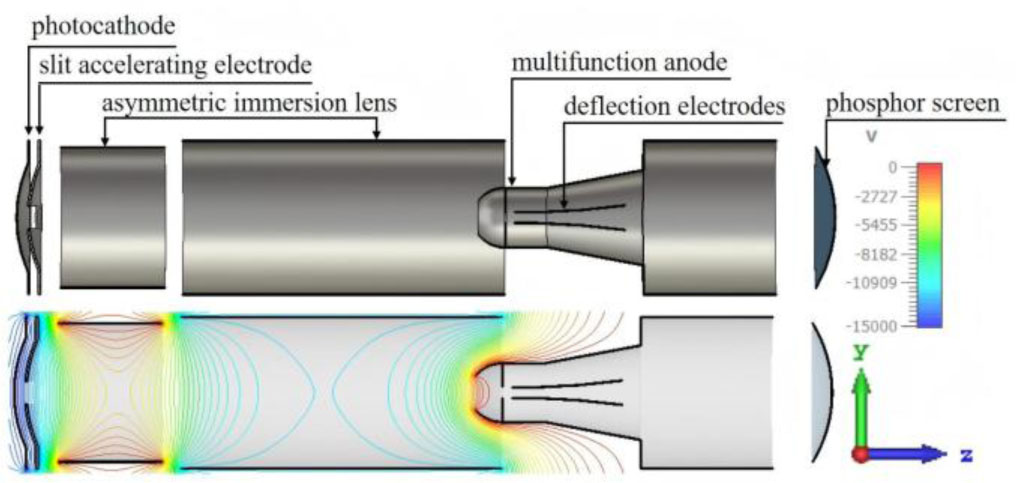
Fig. 1.
Schematic structure of the large-format streak tube and simulated electric-field distribution.
The asymmetric immersion lens consists of a pre-focusing electrode (F1) and a focusing electrode (F2). The pre-focusing electrode partially compensates for the anisotropic electric-field components introduced by the slit accelerating electrode, thereby improving electron-beam transport uniformity and image quality. The multifunction anode comprises an anode cap, a cylindrical electrode, and a conical electrode. The anode cap blocks large-angle electrons emitted from the photocathode, suppressing secondary-electron noise at the anode entrance and reducing the effect of stray light on image formation. A circular aperture with a diameter of 5 mm is positioned near the anode inlet to isolate electric-field interactions between the focusing region and the deflection system. The deflection system employs a multi-fold electrode structure to achieve high deflection sensitivity while maintaining field uniformity. The equipotential distribution of the complete electron-optical system, calculated using the finite integration technique (FIT), is shown in Fig. 1 after operating voltages are applied to each electrode.
The initial state of photoelectron emission is characterized by statistical distributions of energy, emission angle, and spatial position. These emission characteristics were modeled using a Monte Carlo sampling approach [14]. Each sampled electron source comprises 3000 electrons. The initial kinetic energy of the photoelectrons follows a Beta distribution β(1,4) over the energy range of 0–0.6 eV. The emission elevation angle follows a cosine distribution over the range of 0°–90°, while the azimuthal angle is uniformly distributed between 0° and 180°. The initial emission positions are uniformly distributed across the photocathode surface.
Fig. 2 illustrates the Monte Carlo sampling results for the initial energy distribution of 3000 photoelectrons emitted from the photocathode center, showing a most probable energy of 0.15 eV.
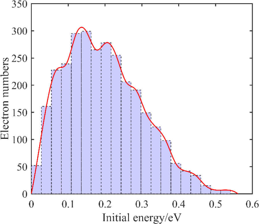
Fig. 2.
Monte Carlo sampling of the initial photoelectron energy distribution.
3. Analysis of the Spatiotemporal Resolution
A. Physical temporal resolution
The ultimate temporal resolution of the streak tube is defined as the transit time spread of the photoelectron pulse arriving at the phosphor screen when electrons are emitted from the center of the photocathode. In the numerical analysis, the CST particle-tracking solver was used to calculate electron trajectories under the simulated electrostatic field distribution.
Fig. 3(a) presents the time point spread function of electrons emitted from the photocathode center. The simulated temporal spread is approximately 3.6 ps. Fig. 3(b) shows the corresponding temporal modulation transfer function (TMTF). When the TMTF amplitude decreases to 0.1, the corresponding temporal frequency is approximately 226.9 ns−1. Therefore, the ultimate physical temporal resolution of the streak tube can be estimated as (1/226.9) ns ≈ 4.4 ps.
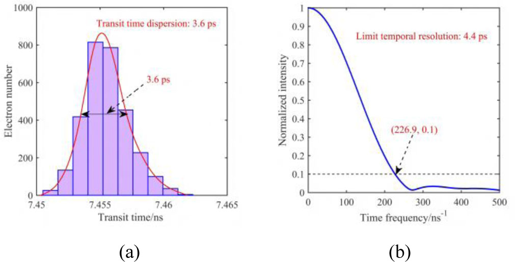
Fig. 3.
Temporal resolution. (a) Time point spread function; (b) TMTF.
To evaluate temporal resolution uniformity across the entire photocathode surface, electron pulses were numerically tracked at multiple emission positions. The X-direction is defined as the slit direction, while the Y-direction corresponds to the scanning direction. As illustrated in Fig. 4, electron emission positions were sampled along the slit direction with a spatial interval of 3 mm. Due to the structural symmetry of the streak tube with respect to the X – O – Y plane, simulations were conducted only within the first quadrant.
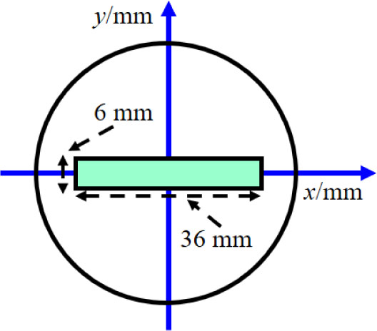
Fig. 4.
Schematic diagram of photoelectron emission position on the photocathode surface.
Fig. 5 shows the calculated TMTF curves for different emission positions on the photocathode. The corresponding temporal frequency range is 220.8 ns−1 to 250.2 ns−1, which corresponds to a physical temporal resolution ranging from 4.0 ps to 4.5 ps. The variation of temporal resolution along the scanning direction is shown in Fig. 6. The results indicate that the temporal resolution uniformity reaches approximately 96 % across the entire photocathode working area of 36 mm × 6 mm.
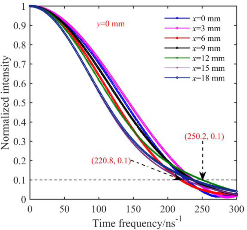
Fig. 5.
TMTFs at different photocathode positions.
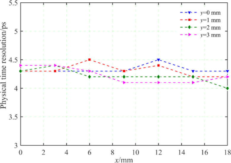
Fig. 6.
Physical temporal resolution of the large-format streak tube versus off-axis distance.
B. Spatial resolution
The spatial resolution of the streak tube is defined as the spatial frequency at which the spatial modulation transfer function (SMTF) decreases to 0.1. In large-format streak tubes, spatial resolution typically degrades near the photocathode edges due to electron-optical aberrations.
To evaluate spatial performance, photoelectrons were emitted from the inner surface of the photocathode along the slit direction at spatial intervals of 3 mm. The electromagnetic field distribution was calculated by solving the discretized Maxwell equations, expressed in (1) and (2). To ensure high numerical accuracy, a refined three-dimensional mesh was employed. The electron trajectories were subsequently tracked, and the resulting spatial electron distribution on the phosphor screen was statistically analyzed.
The calculated SMTFs along both the slit and scanning directions at y = 0 mm and y = 3 mm are shown in Fig. 7(a) ~ Fig. 7(d), respectively. Obviously, the spatial resolution at the center of the photocathode is higher than that at the off-axis position, and the spatial resolution at y = 3 mm is lower than that at y = 0 mm, mainly due to the larger off-axis aberration. Within the entire effective detection area of the photocathode, which is 36 mm × 6 mm, the static spatial resolution is higher than 16 lp/mm.
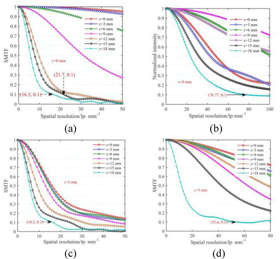
Fig. 7.
Spatial resolution. (a) SMTF along slit direction at y = 0 mm; (b) SMTF along scanning direction at y = 0 mm; (c) SMTF along slit direction at y = 3 mm; (d) SMTF along scanning direction at y = 3 mm.
C. Deflection sensitivity
Deflection sensitivity is defined as the displacement of photoelectrons on the phosphor screen per unit deflection voltage. High deflection linearity is essential for maintaining temporal and spatial fidelity in streak imaging. To evaluate the deflection characteristics, an electron pulse with an initial energy of approximately 0.15 eV was emitted from the photocathode center. Fig. 8(a) shows the simulated electron distribution on the phosphor screen under different deflection voltages. Fig. 8(b) presents the linear relationship between deflection displacement and applied voltage. The simulation results demonstrate that the deflection sensitivity of the proposed streak tube is approximately 58.7 mm/kV, with good linearity across the evaluated voltage range.
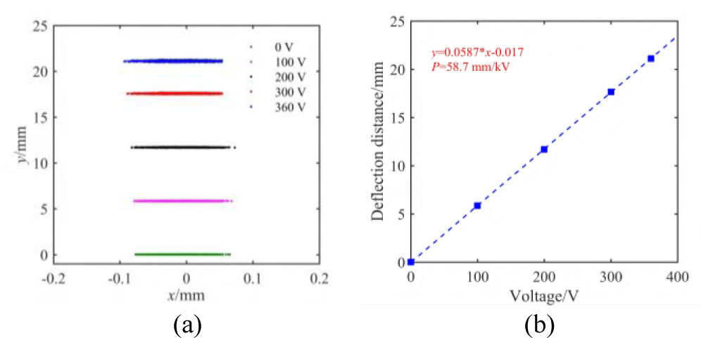
Fig. 8.
Deflection sensitivity. (a) Electron distributions under different deflection voltages; (b) Linear fitting of deflection displacement versus applied voltage.
D. Magnification
Magnification is defined as the ratio between the image size on the phosphor screen and the original emission size on the photocathode. To evaluate the magnification characteristics, photoelectrons were emitted uniformly across a 36 mm × 6 mm region on the spherical photocathode, as illustrated in Fig. 9. Due to the use of electrostatic focusing optics in a large-format configuration, electron-optical aberrations lead to non-uniform magnification between paraxial and edge regions. Fig. 10 shows the simulated electron distribution on the phosphor screen. The magnification increases gradually with increasing radial distance from the optical axis, resulting in a pincushion-type distortion pattern. The overall magnification factor ranges from 0.75 to 0.84 across the working area. Compared with conventional magnifying streak tubes, a smaller magnification factor improves luminance gain, which is beneficial for detecting weak ultrafast optical signals and generating high-brightness output images.
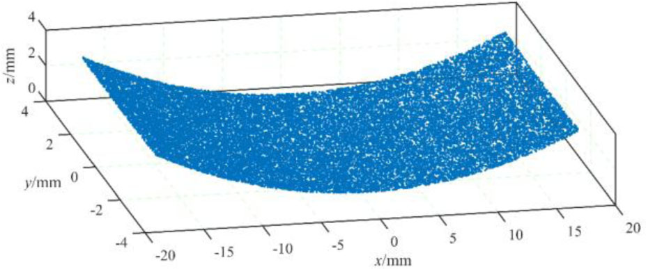
Fig. 9.
Three-dimensional distribution of the electrons on the photocathode.
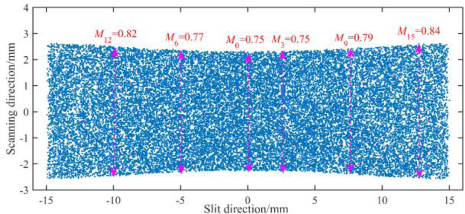
Fig. 10.
The electron distribution on the phosphor screen.
4. Experiment
The fabrication of the large-format streak tube primarily involves photocathode preparation, phosphor screen deposition, and vacuum tube sealing. An S20 photocathode was used to provide spectral response in the visible wavelength range of 400–800 nm. A P43 phosphor screen was used to obtain high anode efficiency and generate high-luminance visible output images with peak emission at approximately 548 nm. The streak tube uses an all-metal, glass-sealed structure, providing high mechanical stability and strong resistance to electromagnetic interference. To suppress electrical breakdown and improve insulation performance, a Cr2O3 insulating layer was deposited on the inner surface of the glass envelope. The fabricated prototype of the large-format streak tube is shown in Fig. 11. During initial high-voltage testing, a slight vacuum breakdown was observed between the accelerating electrode and focusing electrode. To ensure stable operation and prevent discharge, the operating voltage was reduced to −10 kV in the subsequent experimental measurements.
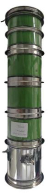
Fig. 11.
Prototype of the novel large-format streak tube.
A. Photocathode radiant sensitivity
Photocathode radiant sensitivity (PRS) is defined as the ratio between the generated photocurrent and the incident optical radiation power at a specified wavelength, typically expressed in mA/W. PRS determines the detectable spectral range and detection efficiency of the streak tube. In the measurement setup, monochromatic illumination with an optical intensity of 1 mW/m2 was applied to the photocathode surface. A constant DC acceleration voltage of +200 V was applied between the photocathode and the slit accelerating electrode. The measured PRS spectrum is shown in Fig. 12. The results indicate that the maximum PRS reaches approximately 38 mA/W at a wavelength of 550 nm, demonstrating high detection efficiency in the visible spectral region. The integral photocathode sensitivity of the fabricated streak tube is measured to be 190 μA/lm, indicating suitability for visible ultrafast optical pulse diagnostics.
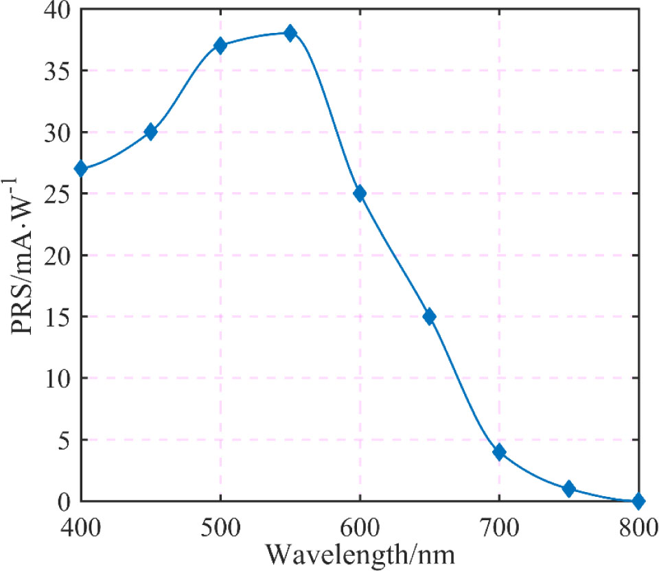
Fig. 12.
Photocathode radiant sensitivity of the large-format streak tube.
B. Spatial-resolution measurement
The static spatial resolution of the large-format streak tube was evaluated using a USAF 1951 resolution test target. During the measurement, high voltage was applied to the electron-optical electrodes while the deflection plates were maintained at zero potential to eliminate scanning effects. An MR2 image radiometer was used to record the target images. Due to the structural symmetry of the streak tube, spatial resolution was evaluated only along the positive slit direction. Fig. 13 presents the measured spatial resolution at different off-axis positions along the photocathode. The experimental results demonstrate that the static spatial resolution exceeds 25.4 lp/mm within the 18 mm central photocathode region and remains above 14.25 lp/mm across the entire 36 mm × 6 mm working area. These results are consistent with numerical predictions presented in Section 3.
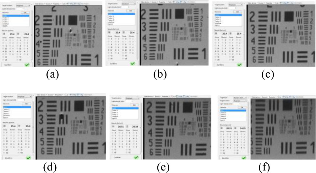
Fig. 13.
Spatial resolution of the large-format streak tube. (a) Center: 25.4 lp/mm; (b) Off-axis 3 mm: 25.4 lp/mm; (c) Off-axis 6 mm: 25.4 lp/mm; (d) Off-axis 9 mm: 25.4 lp/mm; (e) Off-axis 12 mm: 20.16 lp/mm; (f) Off-axis 15 mm: 14.25 lp/mm.
C. Deflection sensitivity measurement
Deflection sensitivity was experimentally evaluated under an operating voltage of −10 kV. When no deflection voltage was applied, the cathode slit image was centered on the phosphor screen and recorded using a CMOS camera with an effective optical magnification factor of 0.475, as shown in Fig. 14(a). When a deflection voltage of +100 V was applied, the slit image shifted by 459 pixels along the scanning direction, as shown in Fig. 14(b). Considering a pixel size of 6.5 μm, the deflection sensitivity can be calculated as [(459 pixels × 6.5 m/pixel)/0.1 kV]/0.475 = 62.8 mm/kV.
The experimentally measured deflection sensitivity is slightly higher than the simulated value. This is mainly due to the edge-field effect of the scanning deflection plates.
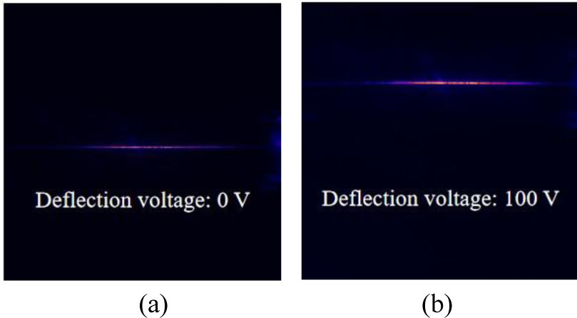
Fig. 14.
Electron distributions under different deflection voltages. (a) Deflection voltage = 0 V; (b) Deflection voltage = +100 V.
D. Magnification and distortion measurement
Magnification is defined as the ratio between the linear dimension of the output image on the phosphor screen and the corresponding dimension of the input image on the photocathode. Because the streak tube uses an electrostatic focusing system, the magnification varies across the photocathode surface, leading to geometric distortion in the output image. Magnification was experimentally measured at multiple photocathode positions, as shown in Fig. 15. The detailed magnification data measured at different radial positions are summarized in Table 1. The measured magnification at the photocathode center is approximately 0.76. The magnification increases gradually with increasing radial distance from the optical axis. The experimental results confirm the presence of pincushion distortion, which is consistent with the simulation results described in Section 3.
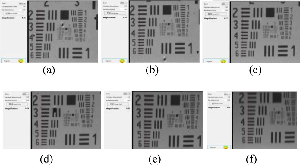
Fig. 15.
Magnification distribution of the large-format streak tube. (a) Center: 0.76; (b) Off-axis 3 mm: 0.76; (c) Off-axis 6 mm: 0.77; (d) Off-axis 9 mm: 0.79; (e) Off-axis 12 mm: 0.81; (f) Off-axis 15 mm: 0.86.
5. Conclusion
A large-format streak tube with high spatiotemporal resolution was designed, numerically analyzed, fabricated, and experimentally characterized for wide-field ultrafast optical diagnostics. The proposed electron-optical system integrates a spherical photocathode, a spherical-slit accelerating electrode, an asymmetric immersion lens, a multi-fold deflection structure, and a spherical phosphor screen. This spherical electron-optical configuration effectively suppresses off-axis aberrations and improves spatial-resolution uniformity over a large photocathode working area. In addition, the slit-type accelerating electrode enhances photoelectron transmission efficiency and helps regulate electron-beam focusing in both the slit and scanning directions, which is beneficial for reducing beam-waist density and improving temporal performance. Three-dimensional electromagnetic simulations show that the proposed streak tube can achieve a spatial resolution exceeding 16.2 lp/mm within a 36 mm × 6 mm effective photocathode area and a physical temporal resolution better than 4.5 ps under the designed operating conditions. The simulated magnification ranges from 0.75 to 0.84, and the deflection sensitivity is calculated to be approximately 58.7 mm/kV, indicating good electron-optical imaging and scanning performance. Based on the optimized design, a prototype streak tube was fabricated and tested. The experimental results show that the S20 photocathode provides a spectral response covering 400–750 nm, with a maximum radiant sensitivity of approximately 38 mA/W at 550 nm and an integral sensitivity of 190 μA/lm. The measured static spatial resolution exceeds 25.4 lp/mm in the central 18 mm region and remains above 14.25 lp/mm across the full 36 mm × 6 mm working area. The measured magnification ranges from 0.76 to 0.86, exhibiting pincushion distortion consistent with the simulation results. The experimentally measured deflection sensitivity reaches 62.8 mm/kV, which agrees reasonably well with the simulated value. These results confirm that the proposed spherical electron-optical design provides an effective approach for simultaneously achieving a large working area, high spatial resolution, and picosecond-level temporal performance in a streak tube. The developed device offers a practical technical route for wide-field ultrafast optical diagnostics and has potential applications in ICF diagnostics, CUP, and high-precision STIL.