
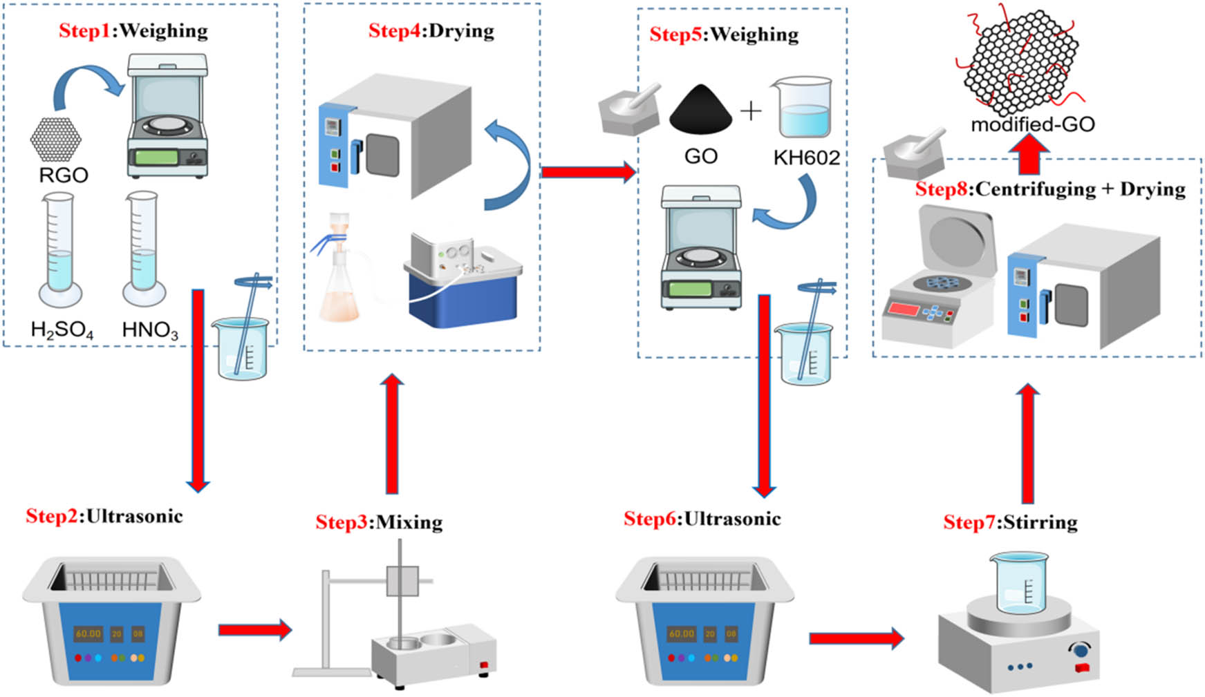
Figure 1
Preparation of modified-GO.
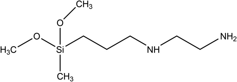
Figure 2
Schematic illustration of the chemical structure of KH602.
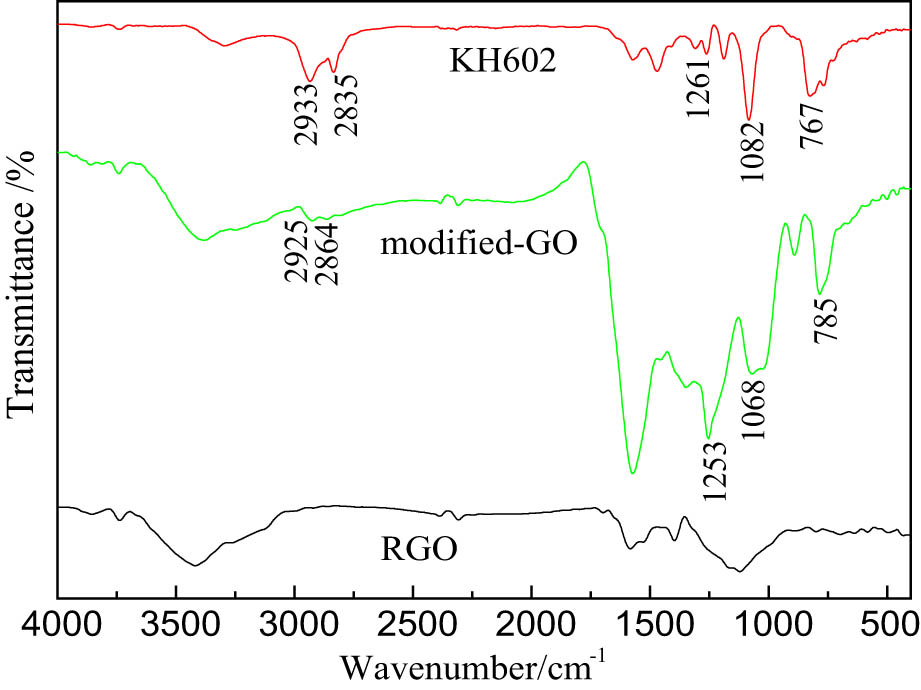
Figure 3
FTIR spectra of KH602, RGO, and modified-GO.
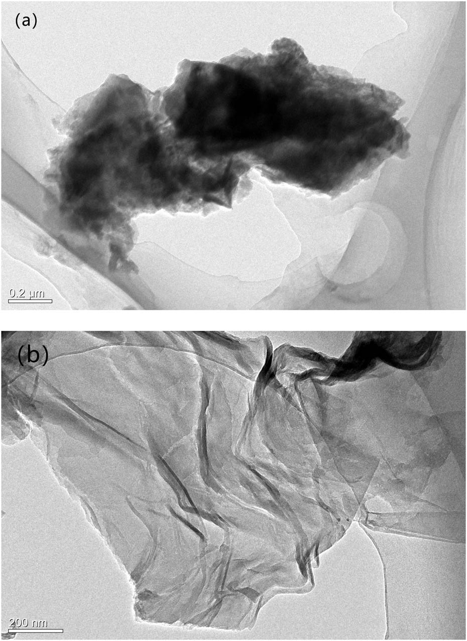
Figure 4
TEM Diagram of (a) RGO and (b) modified-GO.
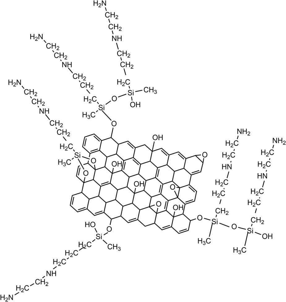
Figure 5
Scheme of the KH602-modified GO.
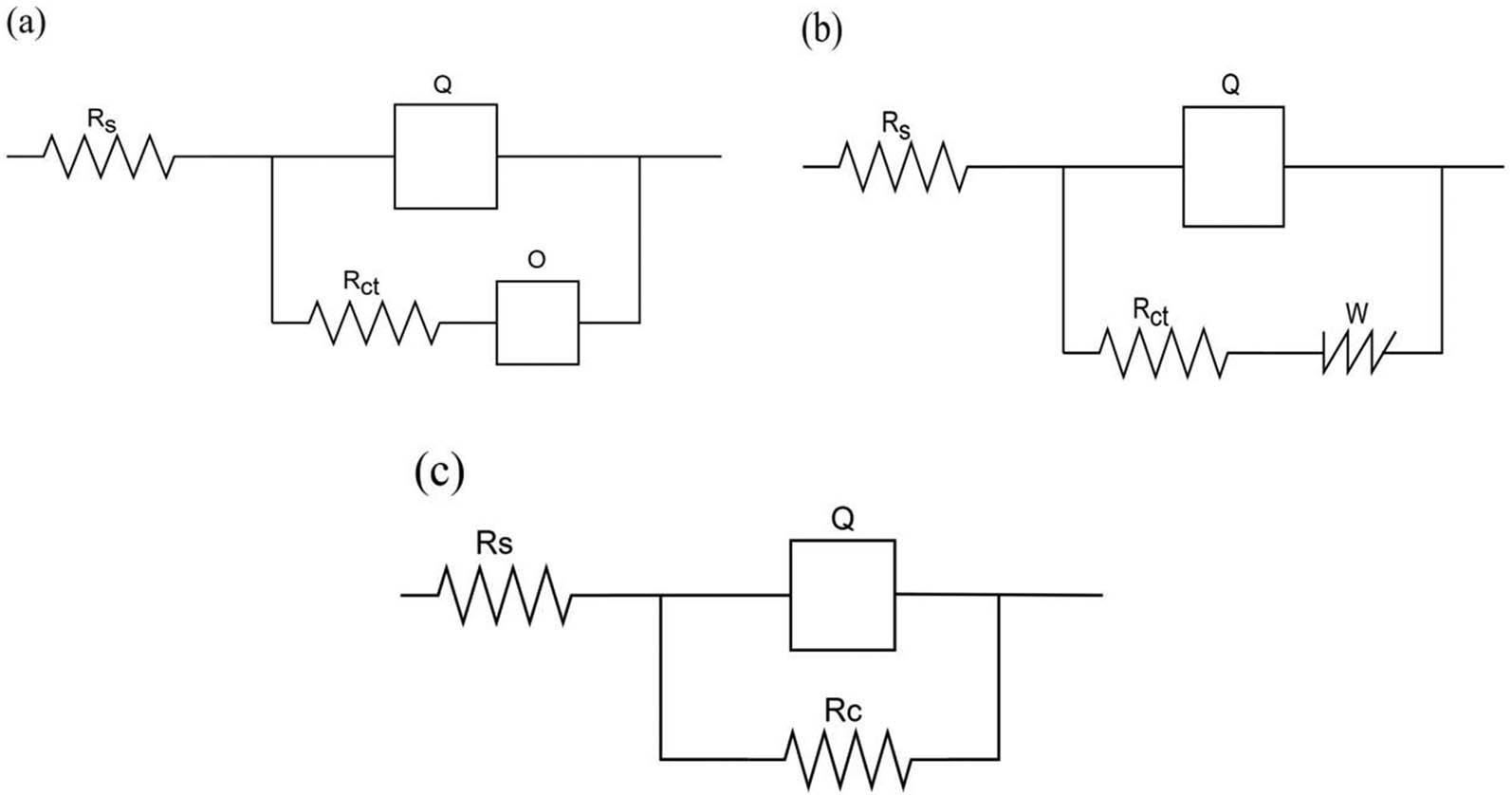
Figure 6
Equivalent circuits for different coatings exposed to 3.5 wt% NaCl solution, (a) varnish at 24 h and 72 h, (b) varnish at 144 h, (c) epoxy/RGO and epoxy/modified-GO.
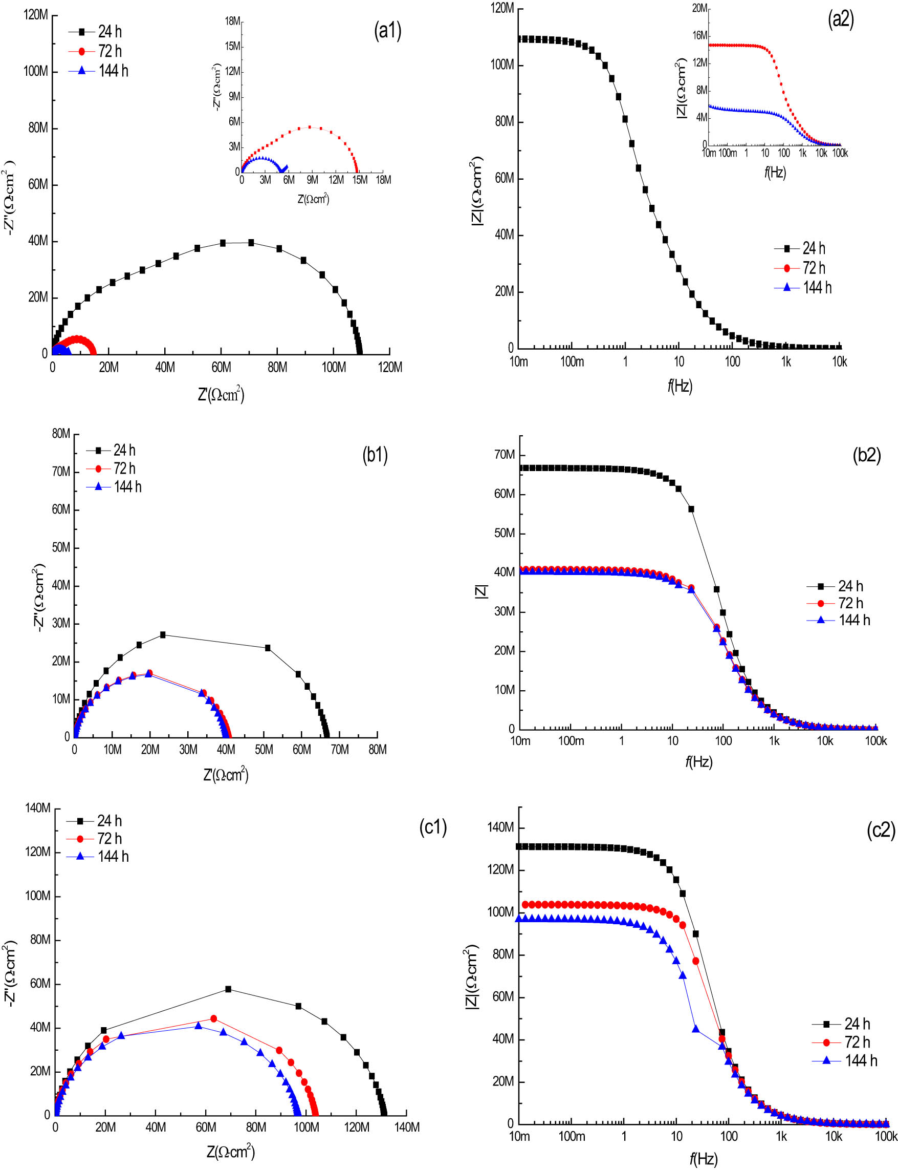
Figure 7
(a1) Nyquist and (a2) bode plots for varnish; (b1) Nyquist and (b2) bode plots for epoxy/RGO (0.1 wt%); (c1) Nyquist and (c2) bode plots for epoxy/modified-GO (0.1 wt%) in the duration of the EIS tests.
Table 2
Fit parameters of varnish immersion in 3.5% NaCl solution during different times
| Time (h) | Q (S sec n /cm2) | n | R ct (Ω cm2) | Chisq |
|---|---|---|---|---|
| 24 | 7.560 × 10⁻¹¹ | 0.9059 | 4.755 × 10⁷ | 1.6 × 10⁻³ |
| 72 | 1.483 × 10⁻¹⁰ | 0.8768 | 4.952 × 10⁶ | 1.8 × 10⁻³ |
| 144 | 6.373 × 10⁻¹⁰ | 0.7726 | 5.043 × 10⁶ | 6.28 × 10⁻³ |
Table 3
Fit parameters of epoxy/RGO (0.1 wt%) immersion in 3.5% NaCl solution during different times
| Time (h) | R C (Ω cm2) | Q (S·sec n /cm2) | n | Chisq |
|---|---|---|---|---|
| 24 | 6.68 × 10⁷ | 8.231 × 10⁻¹¹ | 0.9032 | 8.186 × 10⁻³ |
| 72 | 4.09 × 10⁷ | 1.098 × 10⁻¹⁰ | 0.8828 | 7.14 × 10⁻³ |
| 144 | 4.021 × 10⁷ | 1.136 × 10⁻¹⁰ | 0.8811 | 6.49 × 10⁻³ |
Table 4
Fit parameters of epoxy/modified-GO (0.1 wt%) immersion in 3.5% NaCl solution during different time
| Time (h) | R C (Ω cm2) | Q (S·sec n /cm2) | n | Chisq |
|---|---|---|---|---|
| 24 | 1.313 × 10⁸ | 7.199 × 10⁻¹¹ | 0.9199 | 6.34 × 10⁻³ |
| 72 | 1.039 × 10⁸ | 7.621 × 10⁻¹¹ | 0.9170 | 5.602 × 10⁻³ |
| 144 | 9.696 × 10⁷ | 9.17 × 10⁻¹¹ | 0.9022 | 6.88 × 10⁻³ |
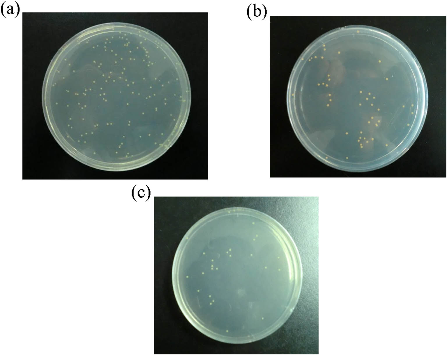
Figure 8
The number of S. aureus colonies for different coatings. (a) Varnish, (b) epoxy/RGO (0.1 wt%), and (c) epoxy/modified-GO (0.1 wt%).
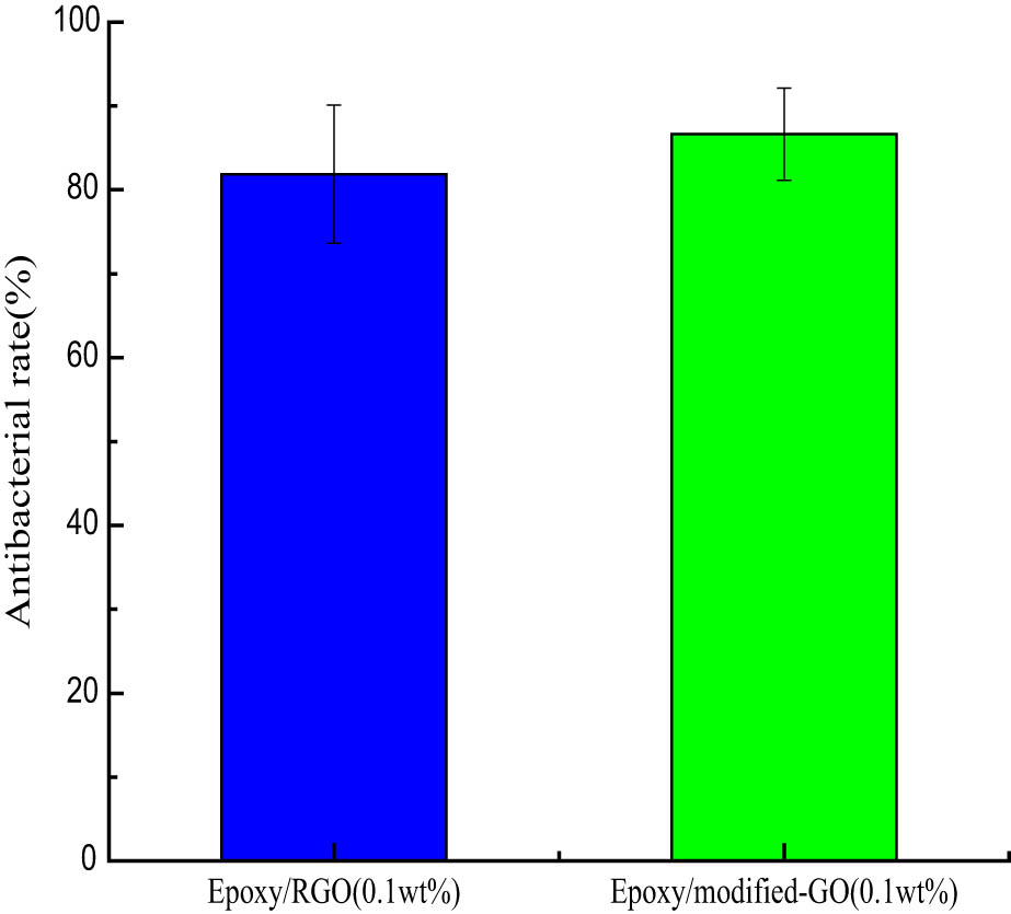
Figure 9
Antibacterial rate of coating.