
1. Introduction
In many technical applications, sliding components operate under conditions where the supply of a conventional lubricant is limited or entirely impossible. This applies particularly to tribological contacts operated under difficult maintenance conditions, in aggressive environments, at elevated temperatures, or in systems where the presence of oil or grease is undesirable. The importance of proper selection of sliding materials is particularly emphasized for highly loaded technical systems, in which the reduction in friction and wear is one of the key requirements for reliable operation of mechanical assemblies [1]. At the same time, when evaluating materials intended for sliding contacts, the conditions of motion initiation and the surface condition after tribological contact are also of significant importance, as demonstrated in studies on the effect of dwell time on the start-up behavior of polymer pairs [2]. In such cases, it becomes essential to develop materials capable of simultaneously carrying loads, reducing resistance to motion, and decreasing wear intensity. Polymer composites belong to a group of materials with particularly high potential in this respect, as their properties can be tailored through the appropriate selection of the matrix, reinforcement, and functional additives. The literature emphasizes that polymer composites are widely considered for tribological applications, since the combination of fibers, fillers, and lubricating additives enables the development of materials with a reduced coefficient of friction and enhanced wear resistance [3].
One direction in the development of such materials is the incorporation of solid lubricants into their structure. These substances can act as components that reduce resistance to motion, particularly under dry or technically dry friction conditions. The effectiveness of solid lubricants is associated mainly with their ability to form a sliding layer or transfer film on the mating surfaces, thereby limiting direct contact between surface asperities [4]. Depending on the material type, operating conditions, and nature of the tribological contact, such additives may influence both the reduction in the coefficient of friction and the wear mechanism. The most frequently investigated solid lubricants include molybdenum disulfide, polytetrafluoroethylene (PTFE), and graphite.
In a review paper on self-lubricating composites containing MoS2, this compound was described as one of the most important fillers used in materials intended for operation under limited lubrication conditions. It was emphasized that MoS2 can be incorporated both into the bulk of the material and in the form of coatings, while its effectiveness depends on the operating conditions and the distribution of the lubricating phase within the composite structure [5]. The influence of PTFE, graphite, and MoS2 on the tribological properties of photocurable resins used in vat photopolymerization was also investigated in the study by Slapnik et al. [6]. It was shown that lubricating additives can significantly reduce friction and wear in such materials, with PTFE exhibiting the strongest effect in the analyzed system. Beneficial effects were also obtained for hybrid systems containing PTFE and MoS2. Compared with the unmodified photocurable resin, the use of fillers reduced the coefficient of friction by up to 52%, while the specific wear rate was reduced by as much as 92%. Numerous studies on sliding composites based on epoxy resins containing molybdenum disulfide confirm that this additive reduces friction and wear [7] and improves mechanical properties [8]. Jamróz et al. [9] showed that the most favorable filler content with respect to friction is 2 wt%, whereas for wear reduction, it is 6 wt%.
PTFE is frequently used as an anti-friction filler due to its ability to form a polymeric transfer film on the surface of the counterelement. In the case of epoxy composites containing PTFE and SiO2 particles, very low values of the coefficient of friction have been reported. These results also showed that the PTFE content and the stability of the transfer layer formed during sliding play an important role in the tribological behavior of such composites. For a composite containing 12.5 wt% PTFE, a coefficient of friction of approximately 0.095 and a wear rate of 8.4 × 10⁻7 mm3/Nm were reported, remaining stable over a sliding distance of approximately 2,000 m [10]. Graphite is also widely used as a solid lubricant in polymer composites. Like MoS2, it possesses a layered crystal structure, which facilitates sliding between adjacent structural planes. Studies on graphite-filled epoxy composites have shown that the addition of 1 wt% graphite reduced the coefficient of friction by approximately 12%, whereas at graphite contents of 3 wt% or higher, the reduction reached approximately 31%. At the same time, a graphite content of approximately 3 wt% was identified as optimal from the tribological point of view [11].
The type of reinforcement used in the composite is also of considerable importance. In fabric-reinforced laminates, the fibers primarily serve a load-bearing function, whereas the polymer matrix is responsible for bonding the reinforcement and transferring stresses between the fibers. Consequently, modification of the matrix with lubricating additives may alter the nature of the tribological contact; however, the resulting effect depends on the interaction of all constituent components, namely, the resin, the reinforcing fabric, and the filler. In carbon-fiber-reinforced epoxy composites modified with MoS2 particles, it has been shown that the presence of this additive can reduce the coefficient of friction under dry sliding conditions. At the same time, carbon fibers can contribute to wear resistance by carrying part of the normal load, limiting excessive deformation and removal of the polymer matrix, and participating in the formation of carbon-rich wear debris in the contact zone [12]. For the epoxy resin alone, the addition of 30 wt% MoS2 reduced the coefficient of friction from approximately 0.40 to 0.15, corresponding to a reduction of about 62.5%, while the wear rate decreased from 0.005 g/min to approximately 0.00185 g/min, representing a reduction of approximately 63% [12]. A reduction in both the coefficient of friction and wear was also reported for carbon fabric/epoxy composites containing hybrid flake graphite–MoS2 particles, which was attributed to the formation of a transfer film on the friction surface. In this case, the addition of 1.2 wt% FGr@MoS2 reduced the coefficient of friction by 21.6% relative to the reference specimen, whereas 1.5 wt% FGr@MoS2 reduced the wear rate by 60.9%. Furthermore, the wear track depth was reduced by approximately 72.1% [13].
In recent years, growing attention has been devoted to the use of UV-curable resins as matrices for functional materials. These materials are attractive due to their rapid curing capability, ease of processing, and potential applications in additive manufacturing and coating technologies. For coatings based on a polyurethane–acrylate UV-curable resin modified with graphite and PTFE, it has been demonstrated that the tribological performance of such systems depends not only on the type of matrix but also on the size and distribution of the solid lubricant particles. The incorporation of PTFE particles with a size of 25 µm reduced the coefficient of friction from 0.746 to 0.395, corresponding to a reduction of approximately 47%, and decreased the wear rate by 62.7% relative to the unmodified tolylene-2,4-diisocyanate (TDI)–hydroxypropyl acrylate (HPA) coating. In contrast, larger PTFE particles, with sizes ranging from 75 to 140 µm, reduced the coefficient of friction by only 6.8%, confirming the significant influence of filler dispersion and particle geometry on tribological behavior [14]. These findings confirm that photocurable resins may serve as promising matrices for self-lubricating materials; however, their tribological performance must be evaluated individually for each specific material system.
Based on the literature analysis, it can be concluded that MoS2, PTFE, and graphite are well-established solid lubricants used in polymer-based tribological materials [3,4,5]. Their effectiveness, however, is not universal and depends on the matrix type, filler content and dispersion, reinforcement type, and sliding conditions [4,5,6]. Previous studies have investigated solid-lubricant-modified photocurable resins [6], PTFE- and graphite-filled epoxy composites [10,11], carbon-fiber-reinforced epoxy composites modified with MoS2-based fillers [12,13], and UV-curable coating systems containing graphite and PTFE [14]. Although these works confirm the anti-friction potential of solid lubricants, they do not fully address the coupled effect of a UV-curable resin matrix, woven-fabric reinforcement, reinforcement type, and filler type under the same dry sliding conditions. Thus, the limitation of the available literature is not the lack of studies on MoS2, PTFE, or graphite as solid lubricants, but the lack of direct comparison of their reinforcement-dependent effectiveness in UV-curable resin-based laminate systems.
UV-curable resin systems are attractive matrices for functional composite materials due to their rapid curing capability and processing flexibility [15,16]. However, in fabric-reinforced laminates, the tribological response cannot be attributed only to the resin or the lubricant, because the reinforcing fabric may also participate in the contact and wear processes after local fiber exposure. Therefore, the research gap addressed in this study concerns the reinforcement-dependent effectiveness of the same solid lubricants in UV-curable resin-based laminates reinforced with either carbon fiber fabric or glass fiber fabric.
Addressing this research gap clarifies that, in UV-curable resin-based woven laminates, the reinforcing fabric can influence tribological behavior not only through its load-bearing function but also by shaping the contact conditions during sliding. Under the applied dry sliding conditions, the results indicate that the effectiveness of solid lubricants is affected by the combined contribution of the resin surface layer, filler particles, exposed fibers, wear debris, and the steel counterelement. This provides new insight into why the same lubricant may produce different friction and wear responses in laminate systems based on the same UV-curable matrix.
The aim of the study is to assess the applicability of UV-curable resin-based composite laminates containing solid lubricants as potential materials for sliding components. The investigated laminates were reinforced with carbon or glass fiber fabric and impregnated with a UV-curable resin modified with graphite, molybdenum disulfide, or PTFE. The analysis focused on the influence of reinforcement type and filler type on friction and wear behavior in contact with C45 steel under technically dry sliding conditions.
2. Materials and methods
2.1. Materials
The study was conducted on composite laminates manufactured using a UV-curable resin supplied by ANYCUBIC®. The resin belongs to the group of liquid photopolymer resins designed for curing by UV/visible light radiation with a wavelength of 405 nm. Such materials are typically reactive systems containing acrylate/methacrylate oligomers or prepolymers, reactive monomers acting as diluents, and photoinitiators responsible for initiating the polymerization process upon exposure to radiation [15,16]. According to the available safety data sheet for the ANYCUBIC UV resin, the main constituents are urethane acrylate, an acrylate monomer, and a photoinitiator [17]. Upon irradiation, the photopolymerization reaction is initiated, leading to the formation of a cross-linked polymer network, the properties of which depend on the resin composition, the degree of conversion of reactive bonds, and the curing conditions [16,17].
Carbon fiber and glass fiber fabrics were used as reinforcement, with the fibers arranged at an angle of 90° relative to one another. The polymer matrix was modified by the addition of one of three solid lubricants: molybdenum disulfide (MoS2) in powder form, PTFE in flake form, and graphite in powder form (Figure 1). Reference specimens were also prepared, in which the matrix consisted of unmodified UV-curable resin.
The mass of resin in each prepared mixture was 10 g. On this basis, the mass of the solid lubricant additive was determined to obtain the assumed weight fraction of the filler in the matrix. The filler contents were selected based on the literature concerning resin-based sliding composites [18,19,20,21,22] and were 2.5 wt% for MoS2, 10.0 wt% for PTFE, and 5.0 wt% for graphite.
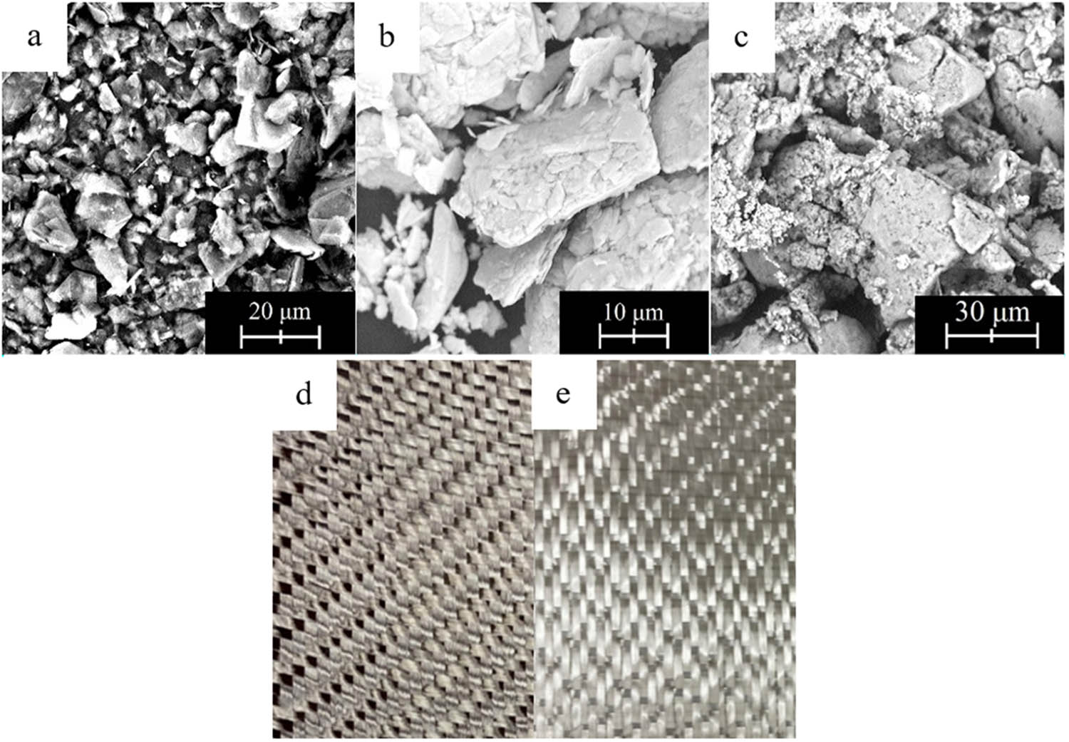
Figure 1
Scanning electron microscopy (SEM) images of the solid lubricants used as fillers: (a) graphite, (b) MoS2, (c) PTFE, and photos of the fabrics: (d) carbon fiber and (e) glass fiber used with the photocurable resin to prepare the specimens.
In this way, eight material variants were prepared, including laminates reinforced with either carbon fiber or glass fiber, both without solid lubricant additives and with the addition of MoS2, PTFE, or graphite. The properties of the fibers, resin, and solid lubricants used are summarized in Tables 1–3, while the complete list of material variants, together with the abbreviated specimen designations, is presented in Table 4.
Table 1
| Property | Carbon fiber | Glass fiber |
|---|---|---|
| Filament diameter (µm) | 7 | >6–9 |
| Density (g/cm³) | 1.80 | 2.55 |
| Color (−) | Black | White |
| Tensile strength (MPa) | 4,900 | ∼3,400 |
| Young’s modulus (GPa) | 230 | 72–76 |
Table 2
Selected properties of the photocurable ANYCUBIC® resin used as the laminate matrix [25]
| Property | Value |
|---|---|
| Viscosity (mPa∙s) | 552 |
| Density in liquid state (g/cm³) | 1.100 |
| Density after curing (g/cm³) | 1.184 |
| Tensile strength (MPa) | 23.4 |
| Elongation (%) | 14.2 |
| Curing wavelength (nm) | 405 |
| Hardness (Sh D) | 79 |
Table 3
| Property | Graphite | MoS2 | PTFE |
|---|---|---|---|
| Particle size (µm) | 4–30 | 16–30 | 20–70 |
| Density (g/cm³) | 2.26 | 4.8 | 2.14 |
| Color (−) | Black | Dark gray | White |
Table 4
Material variants used in the tribological tests, including reinforcement–filler combinations and filler mass fractions
| Fiber type | Filler type | Filler mass fraction (wt%) | Mass (g) | Abbreviated name |
|---|---|---|---|---|
| Carbon | None | — | — | CF + R |
| Carbon | Graphite | 5.0 | 0.526 | CF + R + G |
| Carbon | MoS2 | 2.5 | 0.256 | CF + R + MoS2 |
| Carbon | PTFE | 10.0 | 1.111 | CF + R + PTFE |
| Glass | None | — | — | GF + R |
| Glass | Graphite | 5.0 | 0.526 | GF + R + G |
| Glass | MoS2 | 2.5 | 0.256 | GF + R + MoS2 |
| Glass | PTFE | 10.0 | 1.111 | GF + R + PTFE |
Note: CF – carbon fiber, GF – glass fiber, R – resin, G – graphite.
2.2. Preparation of the specimens
The specimen preparation process began with cutting the carbon fiber and glass fiber fabrics into rectangular pieces measuring 10 mm × 100 mm. These dimensions corresponded to those of the steel plates used as substrates for the fabricated laminates. Subsequently, according to the assumed weight fraction of the filler in the matrix, appropriate amounts of the UV-curable resin and the selected solid lubricant were weighed using a RADWAG laboratory balance.
For specimens modified with solid lubricants, the UV-curable resin was combined with the appropriate filler: graphite, MoS2, or PTFE. The components were placed in closed laboratory containers and mixed manually by shaking for 2 min. The same mixing procedure was applied to all filler-containing resin systems. No sonication or mechanical stirring was used. After mixing, the resin–filler mixtures were used in the lamination process without additional storage. The reference specimens were prepared analogously, omitting the step of adding a solid lubricant.
In the next stage, manual lamination was performed. Before applying the matrix, the steel plates were degreased with ethanol. Then, using a brush, the first layer of resin or filler-containing resin was applied to their surface. This layer was cured under a UV lamp for 4 min. A lamp with a wavelength of λ = 405 nm was used. After preliminary curing, a piece of reinforcing fabric was placed on the surface, followed by the application of a second matrix layer. The prepared specimen was then placed again under the UV lamp and cured for 10 min. In the final stage, an additional matrix layer was applied and cured for another 20 min.
The applied procedure enabled the fabrication of laminates in which the reinforcing fabric was impregnated with the UV-curable resin and, in the case of modified specimens, with resin containing the selected solid lubricant. Eight specimen variants were prepared, including laminates reinforced with either carbon fiber or glass fiber, both without filler addition and with the addition of MoS2, PTFE, or graphite. A view of the finished specimens intended for tribological testing is shown in Figure 2a.
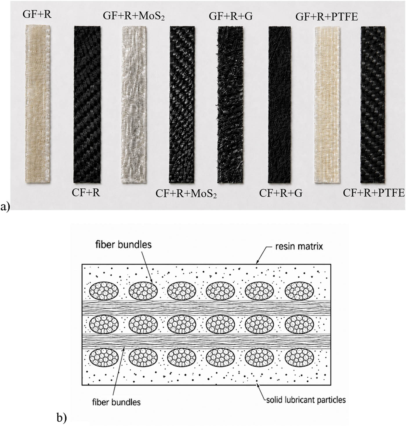
Figure 2
Laminate specimens and schematic representation of their structure: (a) View of the fabricated specimens intended for tribological testing; (b) schematic cross-section of the laminate specimen showing lower resin/filler layer, reinforcing fabric impregnated with UV-curable resin with solid lubricant particles, and upper resin/filler layer.
A schematic representation of the laminate structure is shown in Figure 2b. The specimen consisted of a lower layer of UV-curable resin or resin modified with a solid lubricant, a reinforcing fabric layer impregnated with the same resin system, and an upper resin/filler layer forming the contact surface.
The thickness of the steel substrate was 4 mm. After curing, the average total thickness of the prepared specimen, including the steel substrate and the laminate layer, was 5.5 ± 0.3 mm. The average thickness of the composite laminate layer was 1.5 ± 0.3 mm. Thickness measurements were performed at two locations along each specimen using a caliper, and the reported value represents the mean thickness of the tested specimens.
2.3. Tribological tests
Tribological tests were carried out under technically dry friction conditions, without the use of any additional lubricant. The tests were performed on a test stand designed for friction testing under rolling–sliding motion, using a roller-plate configuration (Figure 3). The specimen was a plate with the applied composite laminate, whereas the counterelement was a roller made of C45 steel, with a diameter of 50 mm and a height of 5 mm. The average surface roughness of the roller was Ra = 1.6 µm and was controlled after each change in the tested material.
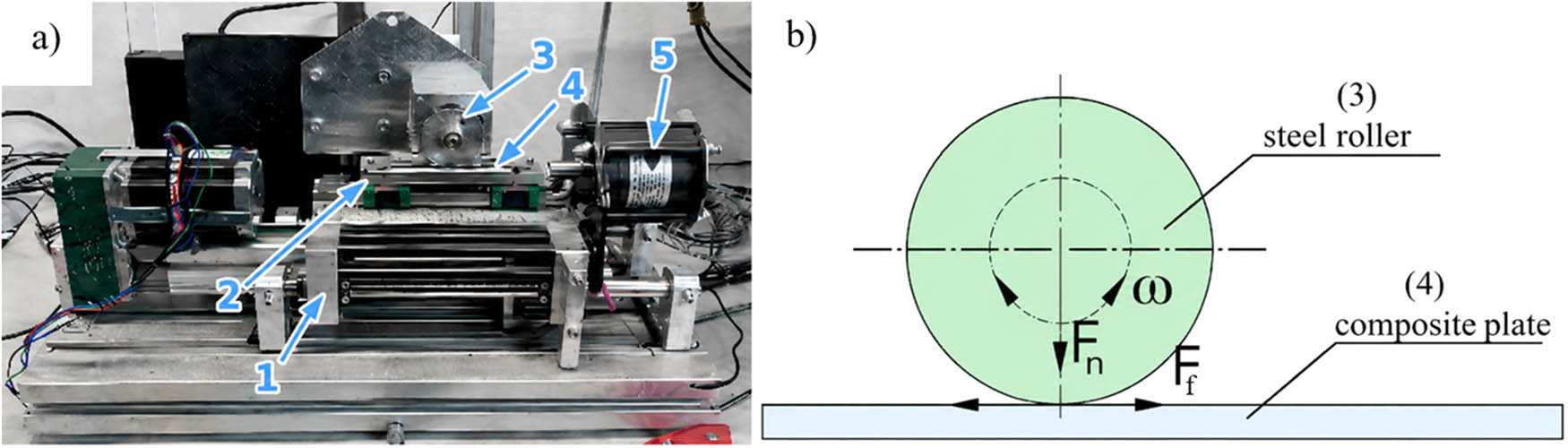
Figure 3
Test stand with the system for friction and wear testing under rolling–sliding motion for the roller-plate configuration: (a) Actual view, (b) Kinematic scheme; test stand components: 1 – lower carriage, 2 – upper carriage, 3 – counter-sample (steel roller), 4 – sample (composite plate), 5 – friction force sensor (strain gauge); Fₙ – normal force, F f – friction force, ω – rotational speed of the steel roller relative to the composite plate.
For each material variant, three measurement repetitions were performed. The tests were conducted under technically dry friction conditions at a normal load of 25 N, which was selected as a fixed reference condition for the comparative evaluation of all laminate variants. The counterelement was driven at a rotational speed of 4 rev/s. The duration of one measurement cycle was 1,000 s, corresponding to a sliding distance of 100 m. Since the aim of the study was to assess the influence of reinforcement type and solid lubricant type, all specimens were tested under identical loading and sliding conditions. This approach made it possible to compare the relative tribological response of the material systems without introducing load as an additional variable. The applied test duration and sliding distance were selected for short-term comparative screening and should not be interpreted as long-term durability or steady-state wear testing. During the test, the kinetic friction force F f was recorded at a frequency of 100 Hz. Based on the measured friction force values and the known normal force, the coefficient of kinetic friction μ k was determined.
2.4. Surface analysis
The laminate surfaces were analyzed before and after the tribological tests. Microscopic observations were performed using a Phenom ProX microscope, which enabled the assessment of changes occurring in the surface layer of the material after the friction process. The analysis included, among others, the condition of the matrix, the visibility and damage of the reinforcing fibers, the presence of wear debris, and the nature of the traces formed in the contact zone.
SEM observations were supplemented by energy dispersive spectrometry (EDS) analysis performed in selected areas of the laminate surfaces. The EDS measurements were used to support the identification of filler-related elements in the modified specimens, especially Mo and S for MoS2-containing specimens and F for PTFE-containing specimens. For graphite-containing specimens, the EDS results were interpreted together with SEM morphology and contrast, since carbon is also present in the resin matrix and carbon fibers.
Additionally, the wear tracks were analyzed using a Leica DCM8 optical profilometer. The profilometric measurements enabled the evaluation of the wear track geometry and determination of their maximum depth. The obtained values were then used to compare the wear intensity of the individual laminate variants.
2.5. Data processing and statistical analysis
During each measurement series, the kinetic friction force was recorded as a function of time. Based on the obtained friction force values and the known normal force, the instantaneous values of the coefficient of kinetic friction were calculated for the individual material pairings. To reduce the influence of local fluctuations in the measurement signal, a simple moving average was determined for the recorded curves using a window of 40 consecutive measurements.
For each material variant, three independent measurement repetitions were performed. On this basis, the mean value of the coefficient of kinetic friction and the standard deviation (SD) were calculated.
Statistical analysis was performed using the mean value obtained for each individual specimen as one independent observation. The coefficient of friction and the maximum wear track depth were analyzed separately. The effects of reinforcement type (carbon-fiber fabric or glass-fiber fabric), lubricating additive (neat resin, graphite, MoS2, or PTFE), and their interaction were evaluated by two-way analysis of variance (ANOVA). Prior to ANOVA, the normality of residuals and homogeneity of variances were verified using the Shapiro–Wilk and Levene tests, respectively. When significant differences were detected, Tukey’s post-hoc test was applied for pairwise comparisons. The significance level was set at p < 0.05. Error bars in the graphs represent SDs calculated from independent specimens.
3. Results and discussion
3.1. Coefficient of friction
During the tribological tests, the kinetic friction force was recorded as a function of time for each material variant. A representative signal fragment, covering the first 30 s of measurement for the CF + R + PTFE laminate sliding against a C45 steel counterelement, is shown in Figure 4. The recorded curve indicates the occurrence of an initial stage of tribological contact stabilization, after which the friction force remained within a relatively narrow range of variation. Such fluctuations are characteristic of sliding pairs operating under technically dry friction conditions and may result from local changes in the contact surface, the displacement of wear debris, and the gradual adaptation of the mating surfaces.
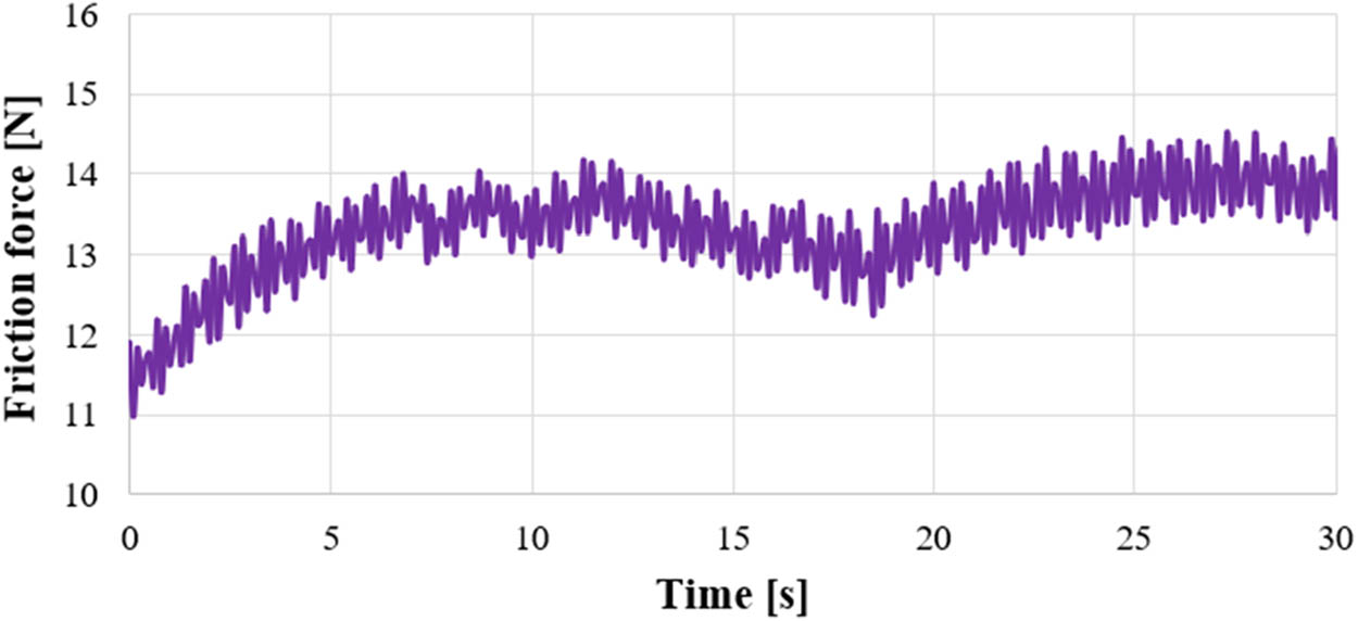
Figure 4
Representative fragment of the kinetic friction force signal recorded during the first 30 s of sliding for the CF + R + PTFE laminate tested against a C45 steel counterelement. The curve shows the initial contact stabilization stage followed by stabilized friction-force fluctuations under technically dry sliding conditions.
The representative friction-force curve shown in Figure 4 was divided into three characteristic stages. The first stage corresponds to the initial running-in of the contact, during which the friction force increased rapidly as the laminate surface and the steel counterelement adapted to each other. The second stage represents contact stabilization, associated with progressive adjustment of the real contact area, local deformation of the resin matrix, and the initial formation and displacement of wear debris. In the third stage, the friction force fluctuated around a relatively stable level, which can be interpreted as a quasi-steady-state friction stage under the applied short-term dry sliding conditions. The observed fluctuations in this stage are result from local changes in the surface layer, intermittent participation of wear debris in the contact zone, and nonuniform exposure of the reinforcing fibers.
Based on the recorded friction force values, the coefficient of kinetic friction was determined for all investigated laminates. Their graphical comparison is presented in Figure 5.
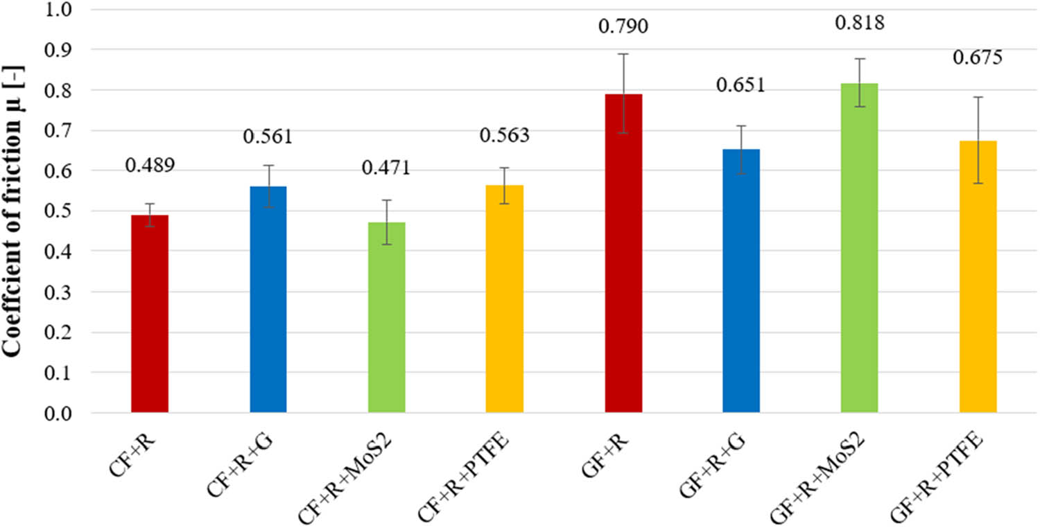
Figure 5
Mean values of the coefficient of kinetic friction for the tested laminates sliding against the C45 steel counterelement. The values above the bars indicate mean values obtained from three measurement repetitions; error bars represent the variability of the results (SD).
For the reference specimens, which did not contain lubricating additives, a lower value of the coefficient of friction was obtained for the laminate reinforced with carbon fiber fabric. For the CF + R variant, the mean coefficient of friction was 0.489, whereas for the GF + R specimen, it reached 0.790. This indicates that, when using the same polymer matrix but a different type of reinforcement, the carbon-fiber-reinforced laminate exhibited considerably more favorable sliding properties. This difference may result from the different nature of the surface contact between carbon or glass fibers and the steel counterelement, as well as from differences in the wear mechanism of the laminate surface layer.
In the group of laminates reinforced with carbon fiber fabric, only the addition of MoS2 resulted in a reduction in the mean coefficient of friction compared with the reference specimen. For the CF + R + MoS2 variant, this value was 0.471, corresponding to a reduction of approximately 3.7% relative to CF + R. Thus, the effect was beneficial, although relatively minor. The incorporation of graphite and PTFE into the matrix of the carbon-fiber-reinforced laminates did not improve their sliding properties. For CF + R + G, the coefficient of friction increased to 0.561, while for CF + R + PTFE, it increased to 0.563, corresponding to increases of approximately 14.7 and 15.1%, respectively, compared with the reference specimen. This may indicate that, in this group of materials, the presence of graphite or PTFE did not promote the formation of a stable sliding layer under the analyzed operating conditions.
A different trend was observed for laminates reinforced with glass fiber fabric. In this case, two of the three applied fillers reduced the coefficient of friction relative to the GF + R reference specimen. The most favorable effect was obtained for the addition of graphite, for which the mean coefficient of friction was 0.651. This corresponds to a reduction of approximately 17.6% compared with the unmodified glass-fiber-reinforced laminate. A beneficial effect was also observed for PTFE, which reduced the coefficient of friction to 0.675, i.e., by approximately 14.6% compared with GF + R. In contrast, the addition of MoS2 resulted in an increase in the coefficient of friction to 0.818, corresponding to an increase of approximately 3.5% relative to the reference specimen.
When comparing all analyzed variants, the lowest coefficient of friction was obtained for the CF + R + MoS2 laminate, for which the mean value was 0.471. In contrast, the highest coefficient of friction was recorded for the GF + R + MoS2 laminate, reaching 0.818. These results indicate that the effectiveness of a given solid lubricant depends not only on its intrinsic anti-friction properties but also on the type of reinforcement used and the interaction between the filler, the matrix, and the fiber surface. Thus, the same additive may have a beneficial effect in one material system, while in another, it may lead to a deterioration of frictional performance.
The comparison presented in Figure 5 highlights a clear reinforcement-dependent effect of the fillers. In carbon-fiber-reinforced laminates, the relative change in the coefficient of friction ranged from a 3.7% reduction for MoS2 to an approximately 15% increase for graphite and PTFE. In contrast, in glass-fiber-reinforced laminates, graphite and PTFE reduced the coefficient of friction by 17.6 and 14.6%, respectively, whereas MoS2 caused a slight increase. This comparison shows that the same solid lubricant may produce an opposite frictional response depending on the reinforcing fabric.
The reinforcement-dependent friction behavior may be related to differences in the contact conditions generated by carbon and glass fibers at the laminate–steel interface. Glass fibers are harder and more brittle than carbon fibers; therefore, their local exposure during sliding may increase the contribution of abrasive interactions and hard wear debris in the contact zone. In contrast, carbon-fiber-reinforced laminates may form a less abrasive contact system, in which carbon-rich wear products and resin debris participate in sliding. This interpretation is based on the friction results and SEM observations of the laminate surfaces and should not be treated as direct evidence of the detailed processes occurring on the steel counterelement.
In carbon-fiber-reinforced laminates, MoS2 gave the lowest mean coefficient of friction, which may be related to its layered structure and low shear strength [4,5,12,13]. However, the formation of a continuous transfer layer on the steel counterelement was not directly verified. Therefore, the beneficial effect of MoS2 in this material group should be interpreted as a possible contribution to more favorable local contact conditions rather than as direct evidence of transfer-layer formation. In contrast, graphite and PTFE did not reduce friction in the carbon-fiber-reinforced laminates, suggesting that these fillers did not provide similarly favorable contact conditions under the applied test parameters.
For glass-fiber-reinforced laminates, graphite and PTFE reduced the coefficient of friction, whereas MoS2 caused a slight increase. This different response may be associated with the participation of exposed glass fibers, wear debris, and filler particles in the contact zone. Graphite and PTFE may have locally reduced shear resistance during sliding, while MoS2 did not show the same effect in this reinforcement system. Overall, these results indicate that the tribological response of solid-lubricant-modified UV-curable laminates depends not only on the intrinsic lubricating properties of the filler, but also on reinforcement-related contact conditions and wear-debris formation.
These findings help explain why the present results do not fully follow the trends reported for unreinforced photocurable resins, epoxy composites, or UV-curable coating systems [6,10,11,14]. In those materials, the tribological response is mainly governed by the matrix–filler–counterelement interaction. In the present laminates, local exposure of the woven reinforcement introduced an additional contact component, which contributed to the reinforcement-dependent response of the same fillers.
The statistical analysis confirmed that the effect of the lubricating additive on the coefficient of friction depended on the type of reinforcement. Two-way ANOVA showed a statistically significant interaction between reinforcement type and additive type (F = 9.566, p < 0.001). This means that the same solid lubricant did not produce the same tribological response in carbon-fiber- and glass-fiber-reinforced laminates.
For the carbon-fiber-reinforced laminates, the lowest mean coefficient of friction was obtained for CF + R + MoS2 (0.471), whereas the reference CF + R material reached 0.489. However, the one-way ANOVA performed within the CF group showed only a borderline effect of additive type (F = 4.035, p = 0.051), and Tukey’s post-hoc test did not confirm statistically significant differences between the CF variants. Therefore, the effect of MoS2 in the CF group should be interpreted as a favorable numerical trend rather than a statistically confirmed reduction.
For the glass-fiber-reinforced laminates, the additive type significantly affected the coefficient of friction (F = 5.415, p = 0.031). The GF + R + G and GF + R + PTFE variants showed lower mean coefficient of friction values than the GF + R reference material, whereas GF + R + MoS2 showed the highest mean value. Tukey’s post-hoc test confirmed a significant difference between GF + R + G and GF + R + MoS2 (p = 0.044). The relatively high scatter observed for GF + R + PTFE indicates that the friction behavior of this material was less stable, which may be associated with local heterogeneity of the contact zone and nonuniform participation of PTFE particles and wear debris during sliding.
3.2. SEM analysis
The surface analysis of the investigated laminates was carried out using SEM. Observations were performed both before and after the tribological tests, which enabled the assessment of changes occurring in the surface layer of the materials as a result of interaction with the steel counterelement. SEM micrographs of the surfaces of laminates reinforced with carbon fiber fabric are presented in Figure 6, whereas those of laminates reinforced with glass fiber fabric are shown in Figure 7.
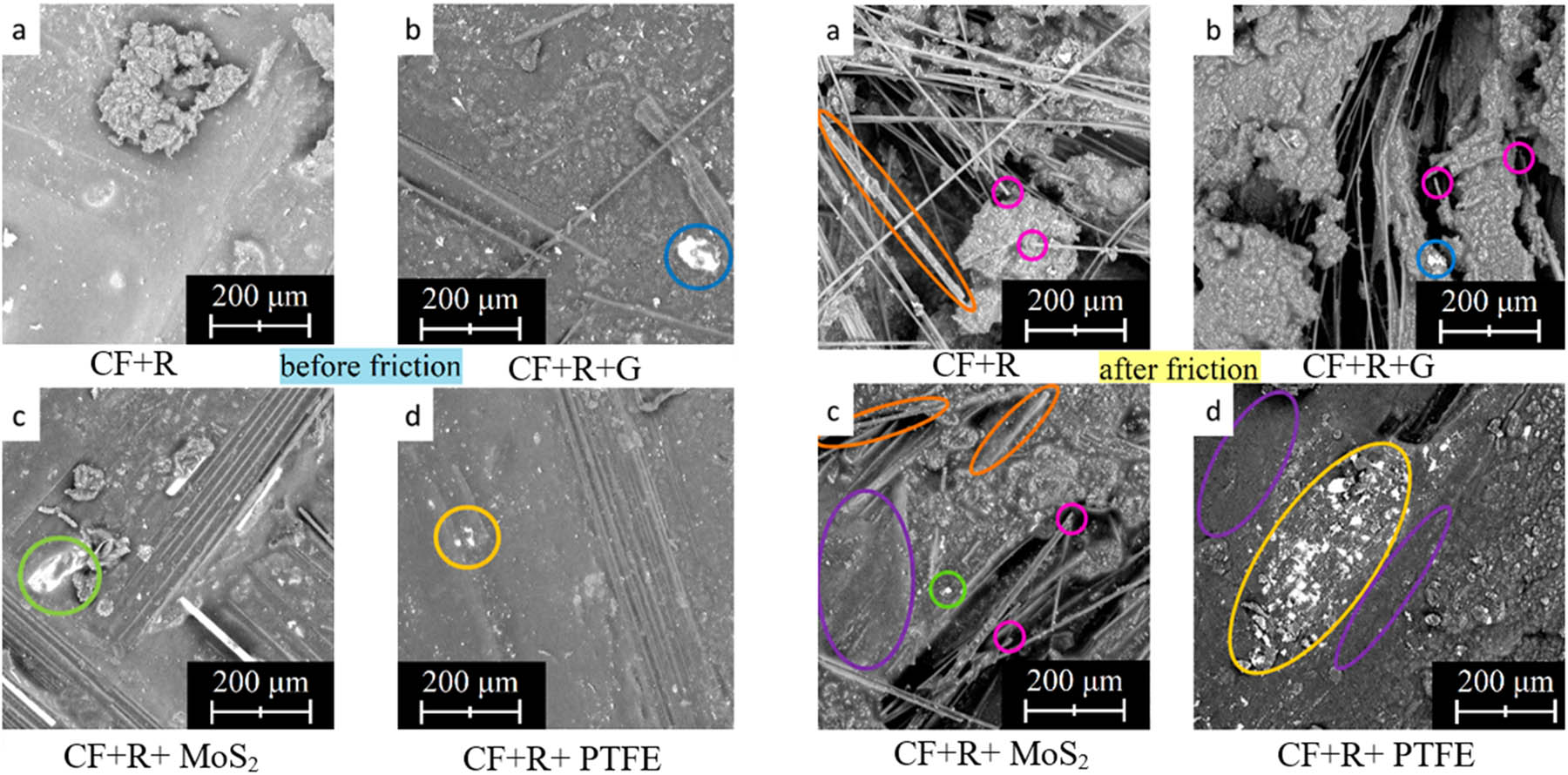
Figure 6
SEM micrographs of the surfaces of carbon-fiber-fabric-reinforced laminates before the tribological tests: (a) CF + R, (b) CF + R + G, (c) CF + R + MoS2, and (d) CF + R + PTFE and after the tribological tests: (a) CF + R, (b) CF + R + G, (c) CF + R + MoS2, and (d) CF + R + PTFE.
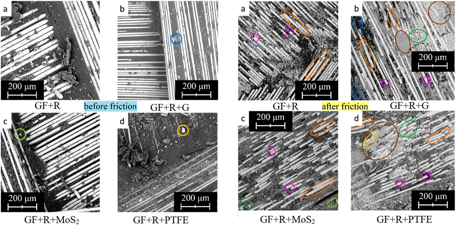
Figure 7
SEM micrographs of the surfaces of glass-fiber-fabric-reinforced laminates before the tribological tests: (a) GF + R, (b) GF + R + G, (c) GF + R + MoS2, and (d) GF + R + PTFE and after the tribological tests: (a) GF + R, (b) GF + R + G, (c) GF + R + MoS2, and (d) GF + R + PTFE.
In the case of laminates reinforced with carbon fiber fabric, proper impregnation of the fibers with the UV-curable resin was visible before the friction process. The matrix regions exhibited a relatively smooth structure, and due to the dark color of the carbon fibers, the contrast between the reinforcement and the resin was limited. In the specimens modified with solid lubricants, filler particles were identified in the matrix regions based on SEM observations supported by EDS analysis. The EDS results confirmed the presence of elements associated with the applied fillers, particularly Mo and S in MoS2-containing specimens and F in PTFE-containing specimens. In graphite-containing specimens, the identification of graphite particles was based on SEM morphology and contrast together with carbon-rich regions; however, due to the presence of carbon in the resin matrix and carbon fibers, EDS alone cannot unambiguously distinguish graphite from other carbon-containing phases. In the micrographs, the identified filler-related regions were marked with different colors: graphite in blue, molybdenum disulfide in green, and PTFE in yellow.
After completion of the tribological tests, the surfaces of the carbon-fiber-reinforced laminates exhibited changes typical of sliding contact under technically dry friction conditions. Local flattening of the fibers, resulting from their wear, was observed and marked in orange, while local fiber fracture was indicated in pink. In some areas, smoothing of the surface microstructure was also observed and marked in purple. This smoothing may indicate local running-in of the mating surfaces as well as the partial spreading of the matrix material and wear debris along the sliding direction. Such changes indicate that, in the case of carbon-fiber-reinforced laminates, the wear process had a mixed character, involving both deformation and abrasion of the matrix and mechanical damage to the exposed reinforcing fibers.
For laminates reinforced with glass fiber fabric, the SEM images obtained before testing also confirmed proper impregnation of the reinforcement with the UV-curable resin. In contrast to the carbon-fiber-reinforced specimens, a more pronounced contrast between the matrix and the glass fibers was visible, which facilitated observation of the distribution of the structural components. The surfaces of the resin-containing regions exhibited a smooth morphology. The presence of fillers was marked analogously to the carbon-fiber-reinforced laminates, i.e., blue for graphite, green for MoS2, and yellow for PTFE. After the friction process, the surfaces of the glass-fiber-reinforced laminates exhibited a more diverse damage morphology. In addition to fiber flattening due to wear, marked in orange, and fiber fracture, marked in pink, fiber fragmentation was also observed and marked in green. Moreover, the micrographs revealed smearing and smoothing of the resin, marked in brown. The presence of fragmented fiber particles may indicate the contribution of an abrasive wear mechanism, in which detached reinforcement particles or wear debris could act as a third body in the friction zone. This may partially explain the greater instability of the coefficient of friction values observed for some laminates reinforced with glass fiber fabric.
Comparison of the surfaces of both material groups indicates that the type of reinforcement had a significant influence on the wear behavior of the laminates. In the carbon-fiber-reinforced laminates, local wear marks, fiber fractures, and smoothing of the microstructure were predominant. In the case of the glass-fiber-reinforced laminates, additional fiber fragmentation was observed, indicating a more brittle damage character in the contact zone. These results are consistent with the coefficient of friction measurements, in which the glass-fiber-reinforced laminates generally exhibited higher values of this parameter than the corresponding carbon-fiber-reinforced variants.
In the case of the CF + R + MoS2 laminate, SEM observations after sliding showed local surface smoothing and wear marks that differed from those observed for the CF + R reference specimen. Together with the lower mean coefficient of friction, this suggests more favorable local contact conditions, but it does not allow the contact processes at the laminate–steel interface to be identified directly. For glass-fiber-reinforced laminates, the simultaneous presence of filler-related regions, glass-fiber exposure or fragmentation, and resin smearing is consistent with the friction and profilometric results, indicating that a local reduction in friction may occur together with mechanically induced material removal. Therefore, SEM observations should be treated as qualitative support for the friction and wear-track analyses rather than as direct proof of a single dominant wear mechanism.
3.3. Wear analysis
A quantitative assessment of wear of the investigated laminates was carried out based on the profilometric analysis of wear tracks formed after interaction with the steel counterelement. The maximum wear track depth (P t) determined for the individual specimens was adopted as the comparative parameter (Figure 8). A graphical comparison of the mean values of the maximum wear track depth is presented in Figure 9.
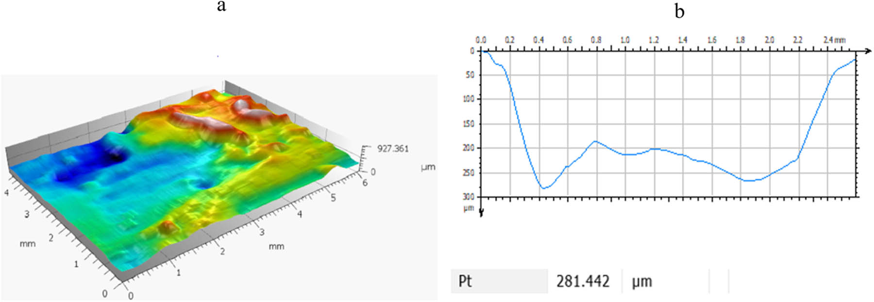
Figure 8
Example of surface topography analysis of a carbon-fiber-reinforced laminate after tribological testing: (a) 3D profilometric scan of the wear track and (b) Cross-sectional profile used to determine the maximum wear track depth P t.
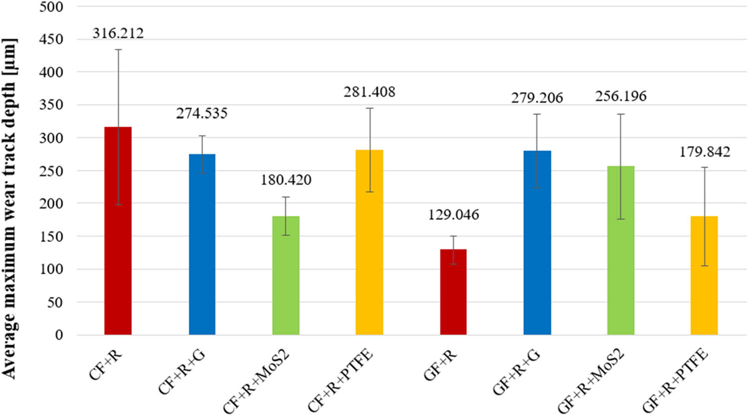
Figure 9
Mean values of the maximum wear track depth Pt for the tested laminates after sliding against the C45 steel counterelement. The values above the bars indicate mean values obtained from three measurement repetitions; error bars represent the variability of the results (SD).
In the case of laminates reinforced with carbon fiber fabric, the highest mean value of the maximum wear track depth was recorded for the reference specimen CF + R, for which this value was 316.212 µm. The addition of each of the analyzed solid lubricants resulted in a reduction in this parameter. For the CF + R + G laminate, the mean maximum wear track depth was 274.535 µm, corresponding to a reduction of approximately 13.2% relative to the reference specimen. In the case of CF + R + PTFE, this value was 281.408 µm, representing a decrease of approximately 11.0%. The greatest improvement was obtained for the CF + R + MoS2 laminate, for which the mean maximum wear track depth was 180.420 µm. This corresponds to a reduction of approximately 42.9% compared with the CF + R laminate. This result is consistent with the coefficient of friction measurements, in which the same variant exhibited the lowest value of this parameter among all investigated laminates.
A different pattern of changes was observed for laminates reinforced with glass fiber fabric. The lowest mean value of the maximum wear track depth was obtained for the reference specimen GF + R, for which this value was 129.046 µm. In this material group, the incorporation of solid lubricants into the matrix led to an increase in the wear track depth. For the GF + R + PTFE variant, the mean value was 179.842 µm, corresponding to an increase of approximately 39.4% relative to GF + R. In the case of GF + R + MoS2, the wear track depth increased to 256.196 µm, i.e., by approximately 98.5%, whereas for GF + R + G, it reached 279.206 µm, corresponding to an increase of approximately 116.4% compared with the reference specimen. These results indicate that, in glass-fiber-reinforced laminates, lubricating additives, although in some cases reducing the coefficient of friction, did not simultaneously lead to a reduction in the wear track depth.
The profilometric analysis showed differences in the mean values of the maximum wear track depth between the analyzed laminates; however, these differences were not statistically significant at p < 0.05. Two-way ANOVA did not confirm a significant effect of reinforcement type, additive type, or their interaction on the maximum wear track depth. This result was mainly associated with the high scatter of profilometric measurements, especially for CF + R, GF + R + MoS2, and GF + R + PTFE. Therefore, the wear-track-depth results should be interpreted as observed mean-value trends rather than statistically confirmed differences.
In carbon-fiber-reinforced laminates, the lowest mean maximum wear track depth was obtained for CF + R + MoS2 (180.420 µm), whereas the CF + R reference specimen reached 316.212 µm. Although this corresponds to an approximately 42.9% lower mean value, the difference was not statistically significant in Tukey’s post-hoc test. Therefore, this result should be treated as a favorable tendency requiring confirmation with a larger number of specimens.
In glass-fiber-reinforced laminates, the reference GF + R material showed the lowest mean wear track depth (129.046 µm), whereas the incorporation of solid lubricants resulted in higher mean values. The largest mean value was observed for GF + R + G (279.206 µm). However, because of the scatter of the profilometric data and the limited number of repetitions, these changes should be discussed as numerical trends rather than statistically significant differences. The observed variability may be related to local fiber fragmentation, nonuniform distribution of solid lubricant particles, and differences in the real contact conditions along the wear track.
Considering the profilometric results together with the friction measurements and SEM observations, the tribological performance of the laminates cannot be evaluated only on the basis of the coefficient of friction. In the carbon-fiber-reinforced group, the CF + R + MoS2 laminate showed both the lowest mean coefficient of friction and the lowest mean maximum wear track depth, while SEM observations indicated local surface smoothing and wear marks different from those of the CF + R reference specimen. In the glass-fiber-reinforced group, graphite and PTFE reduced the coefficient of friction, but the filler-containing variants showed higher mean wear track depths than the GF + R reference specimen and SEM revealed glass-fiber exposure, fragmentation, and resin smearing. These observations suggest that reduced friction may coexist with more intensive local material removal when hard fiber fragments and wear debris participate in the contact zone. Since the wear-track-depth differences were not statistically significant, this interpretation should be treated as an integrated explanation of the observed mean-value trends rather than as a confirmed wear mechanism.
The scope of the present findings is limited by the use of one normal load and one sliding distance. Therefore, the results should be treated as a short-term comparative assessment of the investigated laminates under the applied dry sliding conditions, rather than as a complete evaluation of their long-term engineering performance. In practical sliding components, changes in load, contact pressure, sliding distance, counterelement surface condition, temperature, and wear-debris accumulation may influence fiber exposure, filler retention, and the stability of the contact zone. For this reason, the observed ranking of the material variants should be used as a basis for selecting promising systems for further testing, rather than as a direct prediction of long-term performance in engineering sliding applications.
4. Conclusion
Based on the coefficient of friction measurements, SEM observations, and profilometric analysis of wear tracks, the following conclusions were formulated:
The type of reinforcement had a significant influence on the tribological behavior of the laminates. The reference carbon-fiber-reinforced laminate showed a lower coefficient of friction than the corresponding glass-fiber-reinforced laminate, with mean values of 0.489 for CF + R and 0.790 for GF + R, respectively. This indicates that the reinforcing fabric strongly affects the contact conditions between the laminate and the steel counterelement.
The effect of the solid lubricants depended on the reinforcement type. In carbon-fiber-reinforced laminates, only MoS2 reduced the coefficient of friction, although the reduction was relatively small, from 0.489 for CF + R to 0.471 for CF + R + MoS2. In contrast, graphite and PTFE increased the coefficient of friction in this material group. For glass-fiber-reinforced laminates, graphite and PTFE were more effective, reducing the coefficient of friction by approximately 17.6 and 14.6%, respectively, compared with GF + R.
The friction and wear results were not directly correlated. For the coefficient of friction, statistically significant differences were found within the glass-fiber-reinforced group, particularly between GF + R + G and GF + R + MoS2. In contrast, the differences in maximum wear track depth were not statistically significant at p < 0.05. Therefore, the wear-track-depth results should be interpreted as observed mean-value trends rather than statistically confirmed changes in wear resistance. In carbon-fiber-reinforced laminates, the lowest mean wear track depth was obtained for CF + R + MoS2, whereas in glass-fiber-reinforced laminates, the filler-containing variants showed higher mean wear track depths than the GF + R reference specimen.
The different behavior of carbon- and glass-fiber-reinforced laminates may be associated with differences in the contact zone and surface damage morphology. Carbon-fiber-reinforced laminates showed lower mean wear-track-depth values after filler addition, whereas glass-fiber-reinforced laminates showed a greater tendency toward fiber exposure, fragmentation, and abrasive interactions. These observations suggest that the effect of the same solid lubricant depends on the reinforcing fabric; however, the proposed wear mechanisms should be interpreted cautiously because they were not directly quantified.
Among the tested materials, the CF + R + MoS2 laminate showed the most favorable combination of the lowest mean coefficient of friction and the lowest mean wear track depth within the carbon-fiber-reinforced group. However, the wear-track-depth difference was not statistically significant; therefore, MoS2 should be considered a promising additive for carbon-fiber-reinforced UV-curable laminates under the applied test conditions, rather than as a universally confirmed solution.
The results should be interpreted as a short-term comparative assessment under selected dry sliding conditions, including a normal load of 25 N and a sliding distance of 100 m. Further studies should include different load levels, longer sliding distances, optimization of filler content, and quantitative assessment of filler dispersion in order to determine the load sensitivity, durability, and operating limits of the most promising laminate variants.
Funding information
Authors state no funding involved.
Author contributions
M.K.: investigation, methodology, sample making, data processing, validation, original draft writing, reviewing and editing. P.K.: resources, conceptualization, methodology, validation, supervision, original draft writing, reviewing and editing.
Conflict of interest statement
Authors state no conflict of interest.