
Table 1
Parameters of the applied heat treatment procedures.
| No | Heat treatment parameters |
|---|---|
| 1 | As-delivered condition from the steel mill |
| 2 | Normalization: 880°C, 30 min, and air cooling (∼0.1°C/s) |
| Quenching: austenitization at 880°C, 20 min and cooling in H2O (∼270°C/s) | |
| Tempering: 100°C, 120 min, and air cooling | |
| 3 | Normalization: 880°C, 30 min, and air cooling (∼0.1°C/s) |
| Quenching: austenitization at 900°C, 20 min and cooling in transformer oil (∼25°C/s) | |
| Tempering: 100°C, 120 min, and air cooling | |
| 4 | Normalization: 880°C, 30 min, and air cooling (∼0.1°C/s) |
| Quenching: austenitization at 900°C, 20 min and cooling in Durixol W72 (∼100°C/s) | |
| Tempering: 100°C, 120 min, and air cooling | |
| 5 | Normalization: 880°C, 30 min, and air cooling (∼0.1°C/s) |
| Quenching: austenitization at 900°C, 20 min, and cooling with 5 bar air blast (∼5°C/s) | |
| Tempering: 100°C, 120 min, and air cooling | |
| 6 | Normalization: 880°C, 30 min, and air cooling (∼0.1°C/s) |
| Quenching: austenitization at 900°C, 20 min, and cooling with 3 bar air blast (∼3°C/s) | |
| Tempering: 100°C, 120 min, and air cooling | |
| 7 | Normalization: 880°C, 30 min, and air cooling (∼0.1°C/s) |
| Quenching: austenitization at 900°C and 20 min cooling with 1 bar air blast (∼1°C/s) | |
| Tempering: 100°C, 120 min, and air cooling | |
| 8 | Normalization: 880°C, 30 min, and air cooling (∼0.1°C/s) |
| Quenching: austenitization at 900°C, 20 min, and air cooling (∼0.1°C/s) | |
| 9 | Normalization: 880°C, 30 min, and air cooling (∼0.1°C/s) |
| Quenching: austenitization at 900°C, 20 min, and furnace cooling (∼0.01°C/s) |
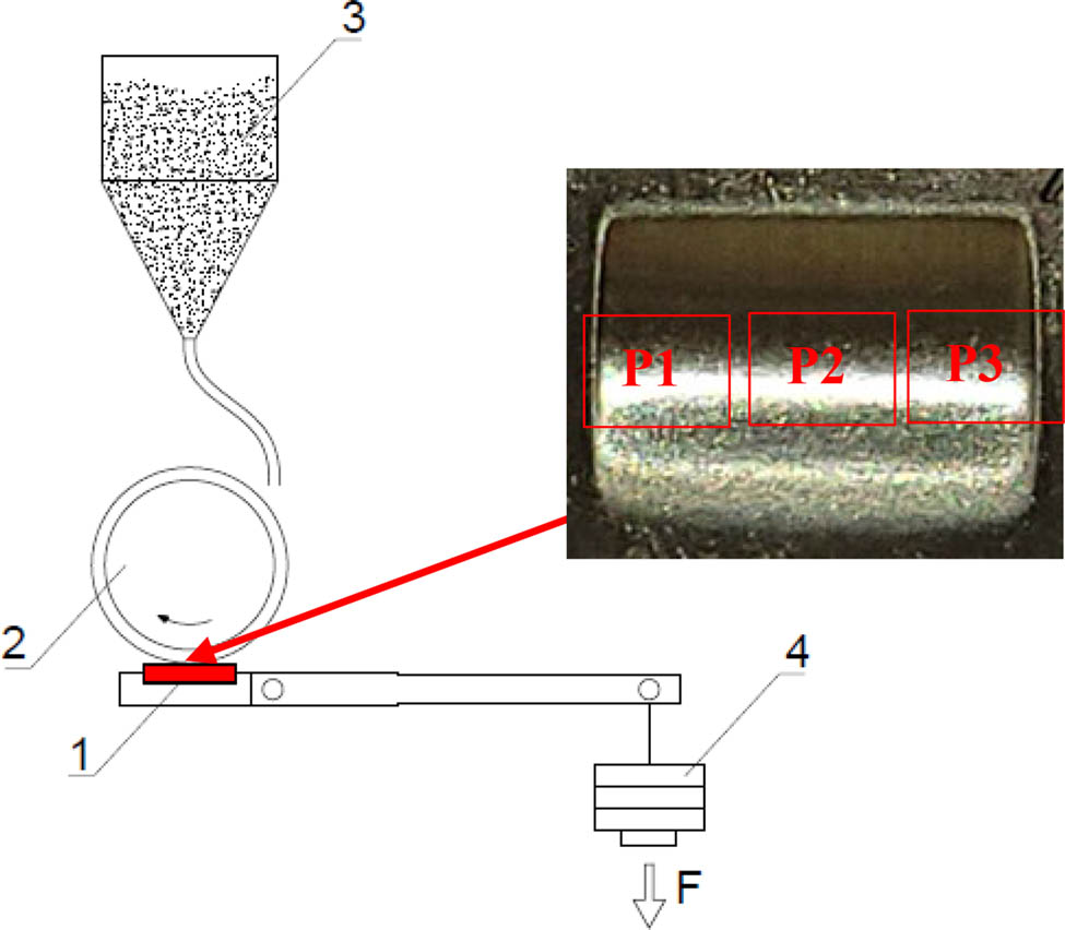
Figure 1
Schematic diagram of the T-07 tribotester. 1 – sample, 2 – rubber-rimmed steel wheel, 3 – abrasive, 4 – load, and P1, P2, and P3 – regions of samples subjected to surface topography evaluation.
Table 2
Results of Levene’s test for homogeneity of variance.
| Effect SS | Effect df | Effect MS | Error SS | Error df | Error MS | F | p | |
|---|---|---|---|---|---|---|---|---|
| Mass wear per 1 m of sliding distance | 0.002684 | 8 | 0.000335 | 0.003295 | 31 | 0.000106 | 3.156335 | 0.00987 |
Table 3
Chemical composition of Hardox 500 steel (in % by weight).
| C | Mn | Si | P | S | Cr | Ni | Mo | V | Cu | Al | Ti | Nb | B |
|---|---|---|---|---|---|---|---|---|---|---|---|---|---|
| 0.29 | 0.74 | 0.28 | 0.007 | 0.001 | 0.61 | 0.06 | 0.018 | 0.012 | 0.010 | 0.054 | 0.003 | — | 0.0009 |
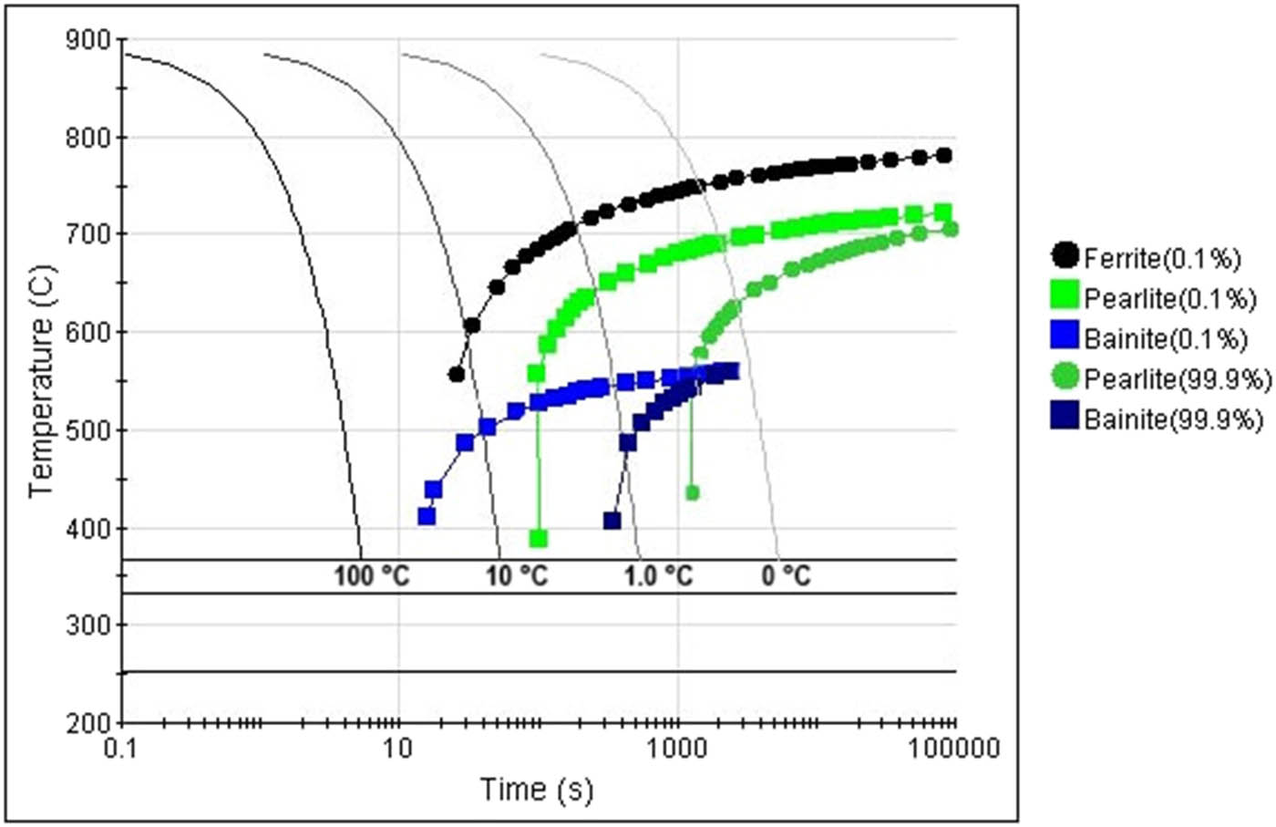
Figure 2
Time–temperature graph for Hardox 500 steel. Assigned temperatures for individual transformations, phases, and components of the structure: pearlite – 736°C, ferrite – 795°C, bainite – 576°C, martensite (50%) – 331°C, martensite (90%) – 252°C, and M S – 366°C.
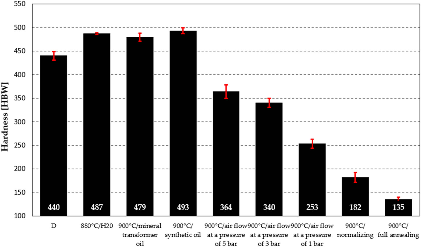
Figure 3
Hardness measurement results of Hardox 500 steel under different heat treatment conditions.
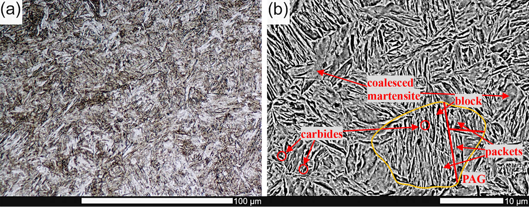
Figure 4
Microstructure of Hardox 500 in the as-delivered condition and etched with 5% HNO3: (a) LM and (b) SEM.
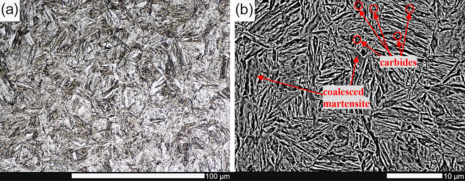
Figure 5
Microstructure of Hardox 500 after water cooling and etched with 5% HNO3: (a) LM and (b) SEM.
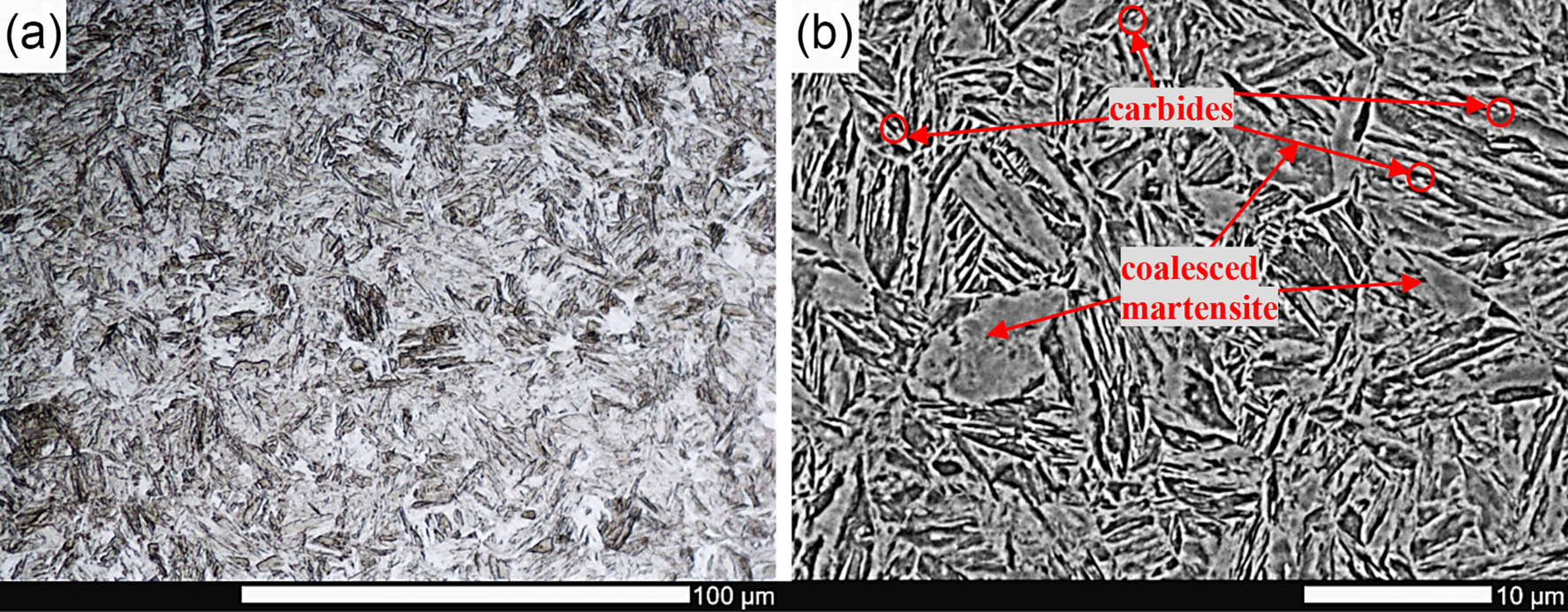
Figure 6
Microstructure of Hardox 500 after mineral oil cooling and etched with 5% HNO3: (a) LM and (b) SEM.
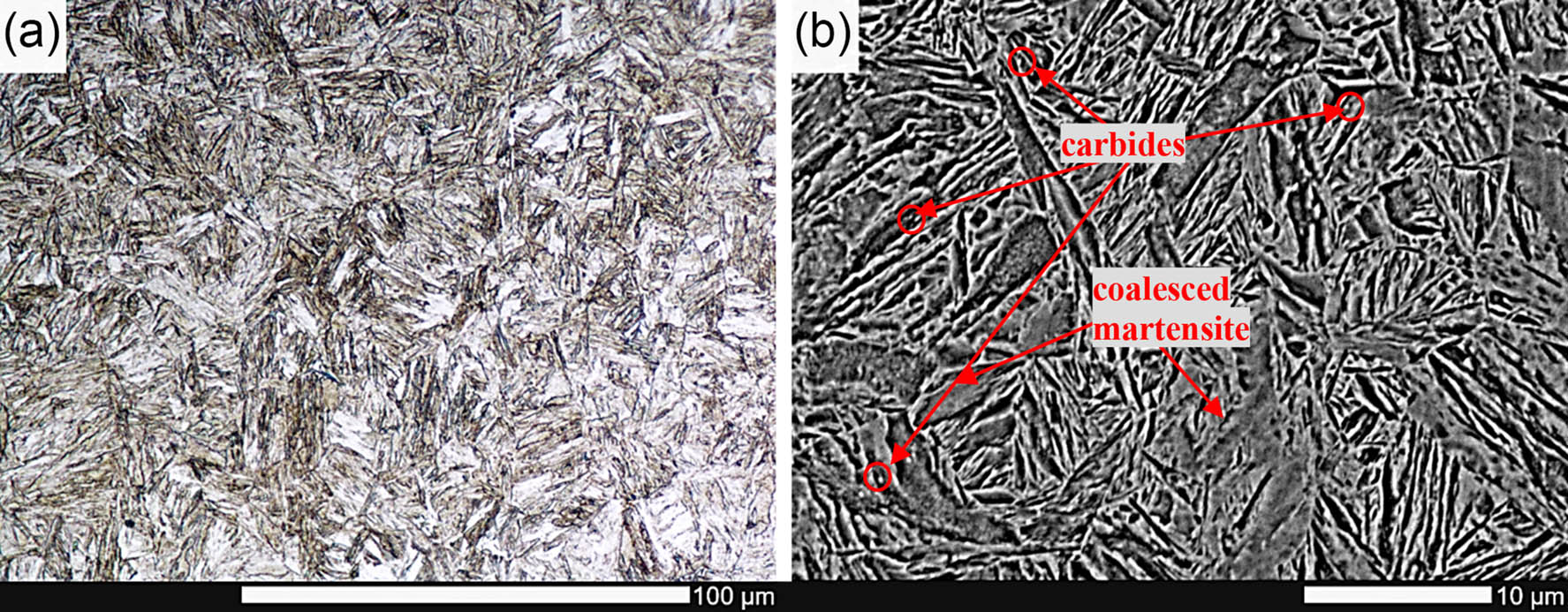
Figure 7
Microstructure of Hardox 500 after synthetic oil cooling and etched with 5% HNO3: (a) LM and (b) SEM.
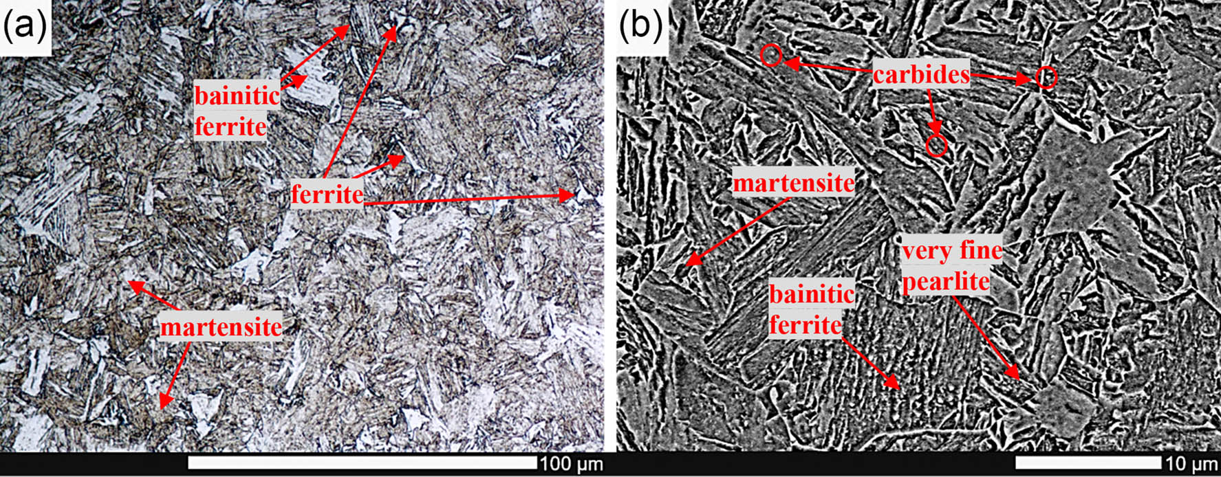
Figure 8
Microstructure of Hardox 500 after air at 5 bar pressure cooling and etched with 5% HNO3: (a) LM and (b) SEM.
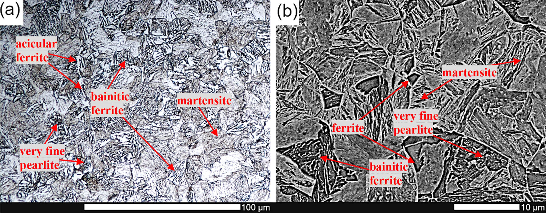
Figure 9
Microstructure of Hardox 500 after air at 3 bar pressure cooling and etched with 5% HNO3: (a) LM and (b) SEM.
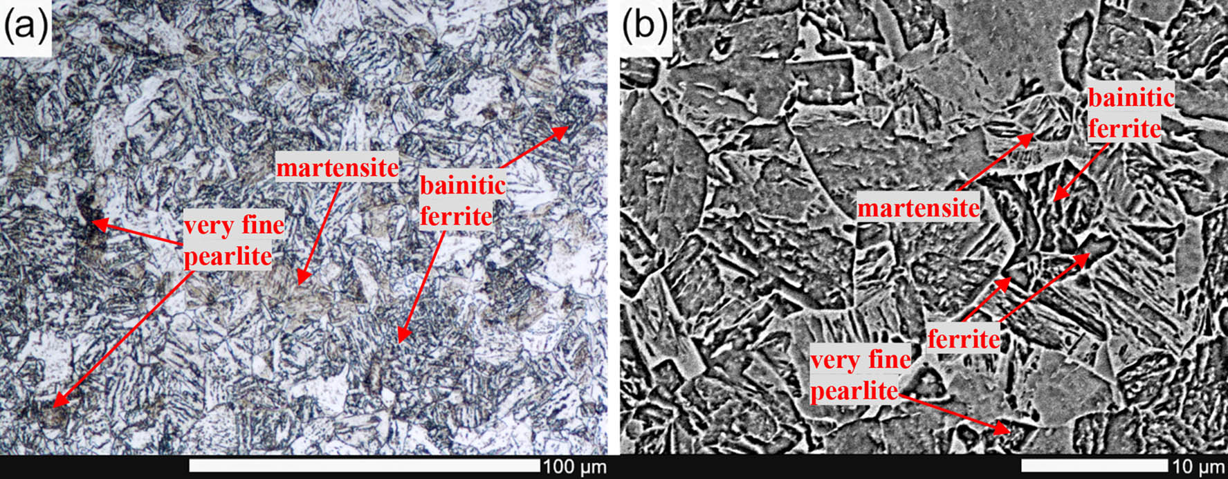
Figure 10
Microstructure of Hardox 500 after air at 1 bar pressure cooling and etched with 5% HNO3: (a) LM and (b) SEM.
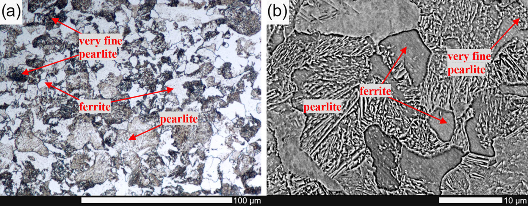
Figure 11
Microstructure of Hardox 500 after air cooling and etched with 5% HNO3: (a) LM and (b) SEM.
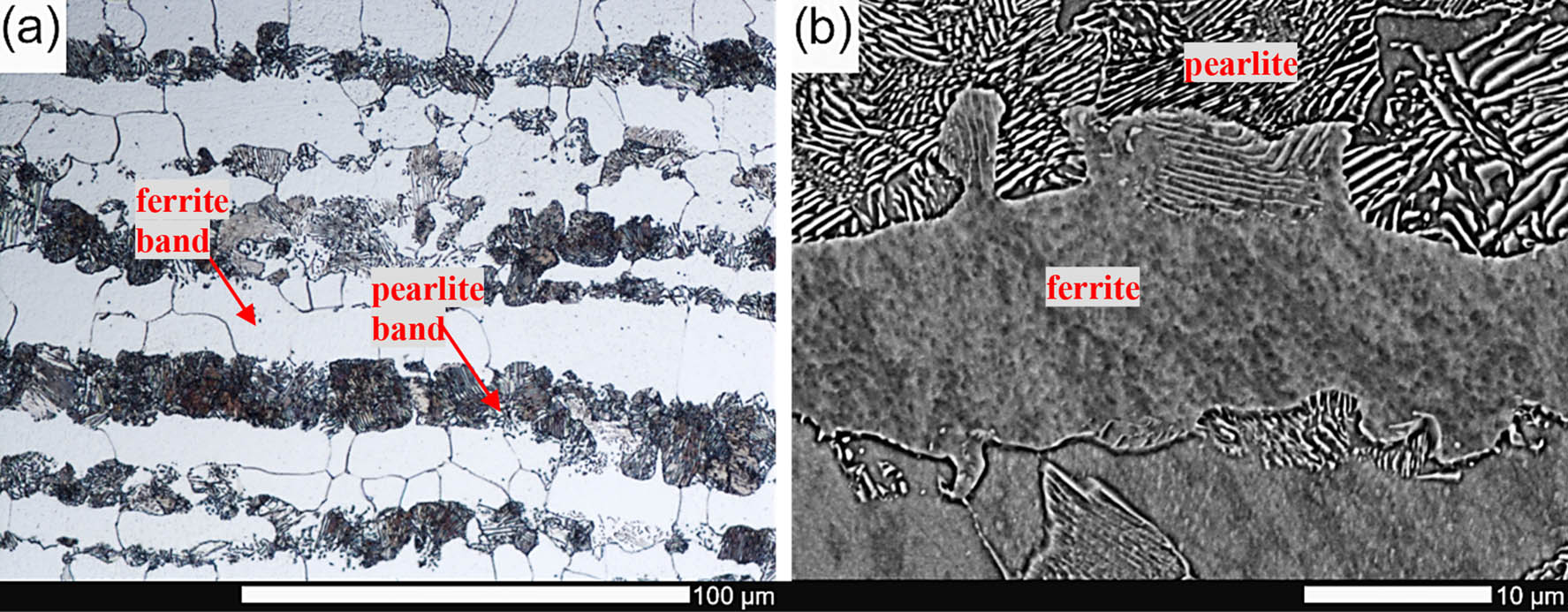
Figure 12
Microstructure of Hardox 500 after furnace cooling and etched with 5% HNO3: (a) LM and (b) SEM.
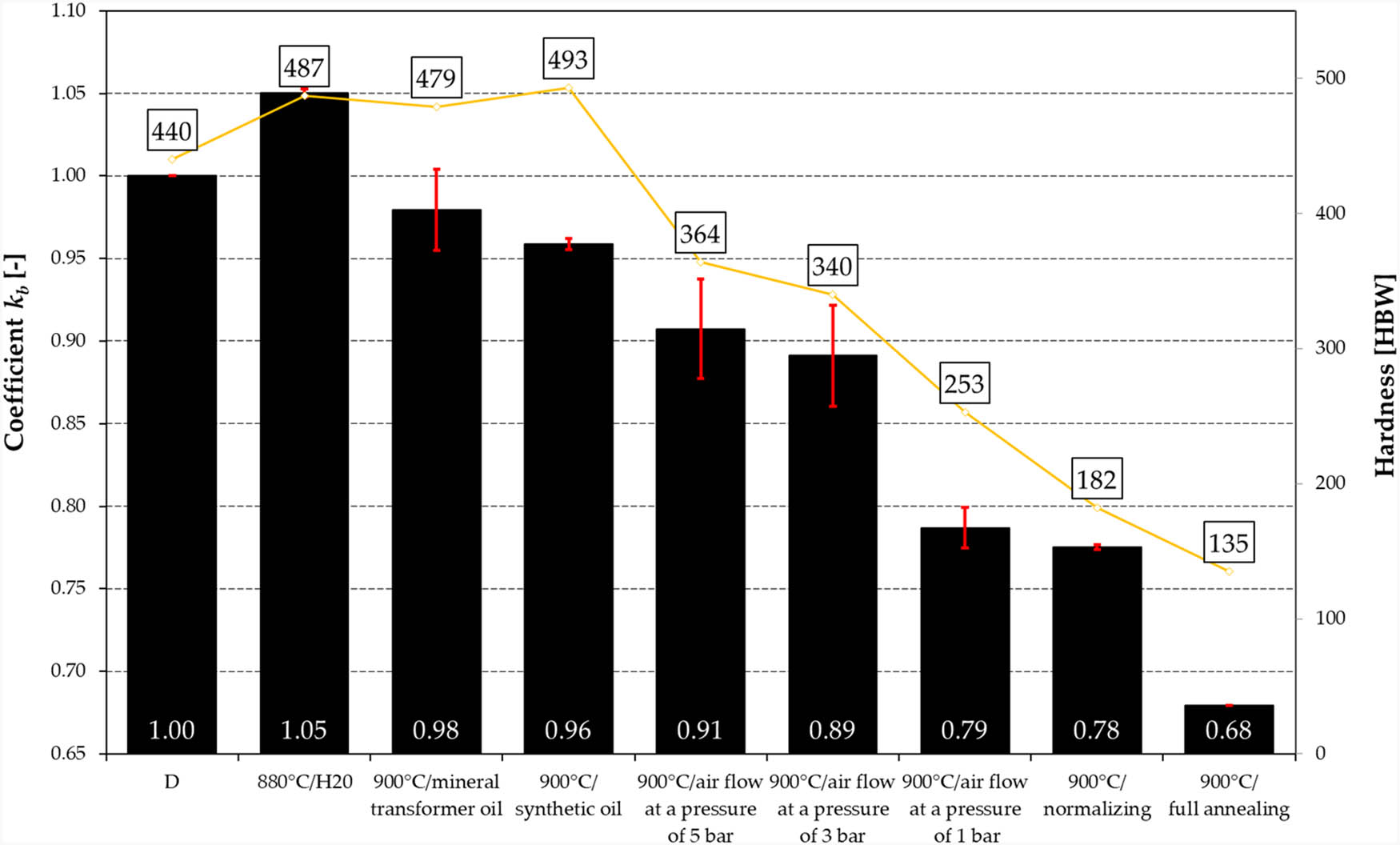
Figure 13
Relative abrasive wear resistance coefficient k b and hardness of Hardox 500 steel under different heat treatment conditions.
Table 4
Results of variance analysis.
| Effect SS | Effect df | Effect MS | Error SS | Error df | Error MS | F | p | |
|---|---|---|---|---|---|---|---|---|
| Mass wear per meter of sliding distance | 0.5748 | 8 | 0.0718 | 0.0157 | 31 | 0.0005 | 141.9316 | 0.0000 |
Table 5
Results of Duncan’s test.
| State of heat treatment | {1} M = 0.7908 | {2} M = 0.7911 | {3} M = 0.8231 | {4} M = 0.8388 | {5} M = 0.8838 | {6} M = 0.9098 | {7} M = 1.0293 | {8} M = 1.0449 | {9} M = 1.1922 |
|---|---|---|---|---|---|---|---|---|---|
| 1 | 0.9867 | 0.0595 | 0.0075 | 0.0000 | 0.0000 | 0.0000 | 0.0000 | 0.0000 | |
| 2 | 0.9867 | 0.0499 | 0.0064 | 0.0001 | 0.0000 | 0.0000 | 0.0000 | 0.0000 | |
| 3 | 0.0595 | 0.0499 | 0.3235 | 0.0008 | 0.0001 | 0.0000 | 0.0000 | 0.0000 | |
| 4 | 0.0075 | 0.0064 | 0.3235 | 0.0074 | 0.0002 | 0.0001 | 0.0000 | 0.0000 | |
| 5 | 0.0000 | 0.0001 | 0.0008 | 0.0074 | 0.1088 | 0.0001 | 0.0001 | 0.0000 | |
| 6 | 0.0000 | 0.0000 | 0.0001 | 0.0002 | 0.1088 | 0.0001 | 0.0001 | 0.0001 | |
| 7 | 0.0000 | 0.0000 | 0.0000 | 0.0001 | 0.0001 | 0.0001 | 0.3292 | 0.0001 | |
| 8 | 0.0000 | 0.0000 | 0.0000 | 0.0000 | 0.0001 | 0.0001 | 0.3292 | 0.0001 | |
| 9 | 0.0000 | 0.0000 | 0.0000 | 0.0000 | 0.0000 | 0.0001 | 0.0001 | 0.0001 |
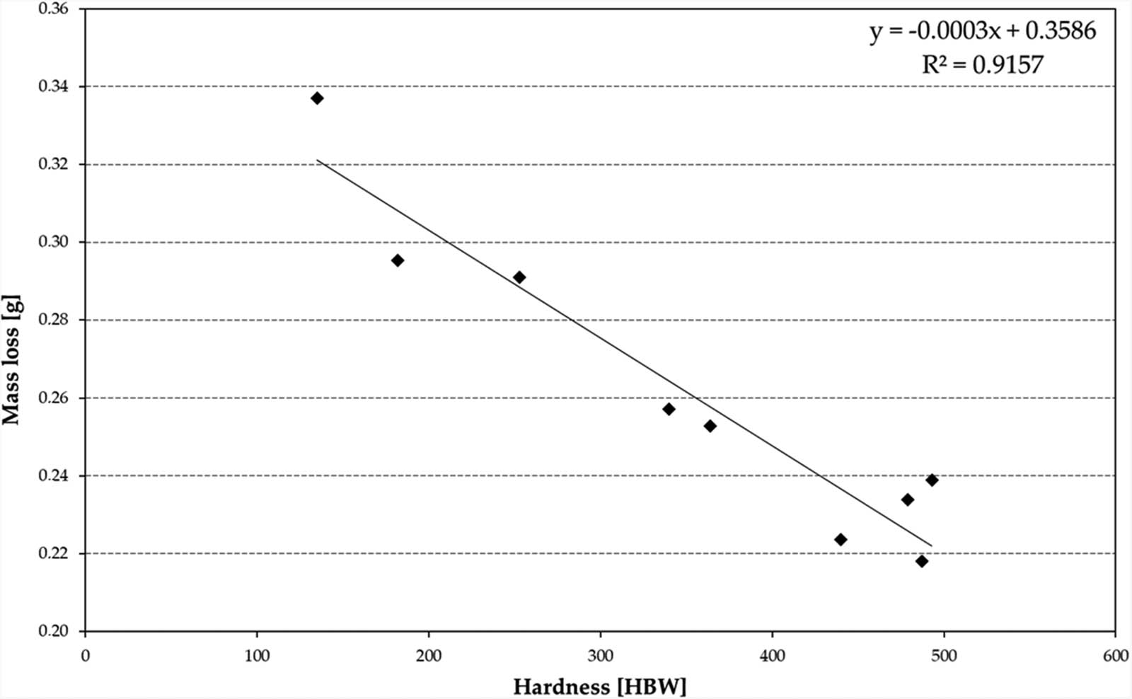
Figure 14
Effect of hardness on the mass loss of Hardox 500 steel under different heat treatment conditions.
Table 6
Mass consumption and volumetric wear loss determined experimentally and predicted by the Archard model.
| State of heat treatment | Actual mass consumption (g) | Actual volumetric wear loss I exp (m3) | Wear coefficient k determined empirically | Wear coefficient k used in the Archard wear model | Theoretical volumetric wear loss I Z (m3) | Relative difference (%) |
|---|---|---|---|---|---|---|
| 1 | 0.2236 | 2.84841 × 10⁻⁸ | 0.009880 | 0.010272 | 3.00644 × 10⁻⁸ | +5.55 |
| 2 | 0.218 | 2.77707 × 10⁻⁸ | 0.010666 | 0.010272 | 2.71511 × 10⁻⁸ | −2.23 |
| 3 | 0.23884 | 2.97898 × 10⁻⁸ | 0.011578 | 0.010272 | 2.76135 × 10⁻⁸ | −7.32 |
| 4 | 0.23385 | 3.04255 × 10⁻⁸ | 0.011490 | 0.010272 | 2.68310 × 10⁻⁸ | −11.82 |
| 5 | 0.25272 | 3.21936 × 10⁻⁸ | 0.009238 | 0.010272 | 3.63384 × 10⁻⁸ | +12.87 |
| 6 | 0.25722 | 3.27669 × 10⁻⁸ | 0.008781 | 0.010272 | 3.89106 × 10⁻⁸ | +18.72 |
| 7 | 0.29104 | 3.70752 × 10⁻⁸ | 0.007391 | 0.005787 | 2.90297 × 10⁻⁸ | −21.69 |
| 8 | 0.29543 | 3.76348 × 10⁻⁸ | 0.005400 | 0.005787 | 4.03325 × 10⁻⁸ | +7.17 |
| 9 | 0.3371 | 4.29427 × 10⁻⁸ | 0.004570 | 0.005787 | 5.43758 × 10⁻⁸ | +26.59 |
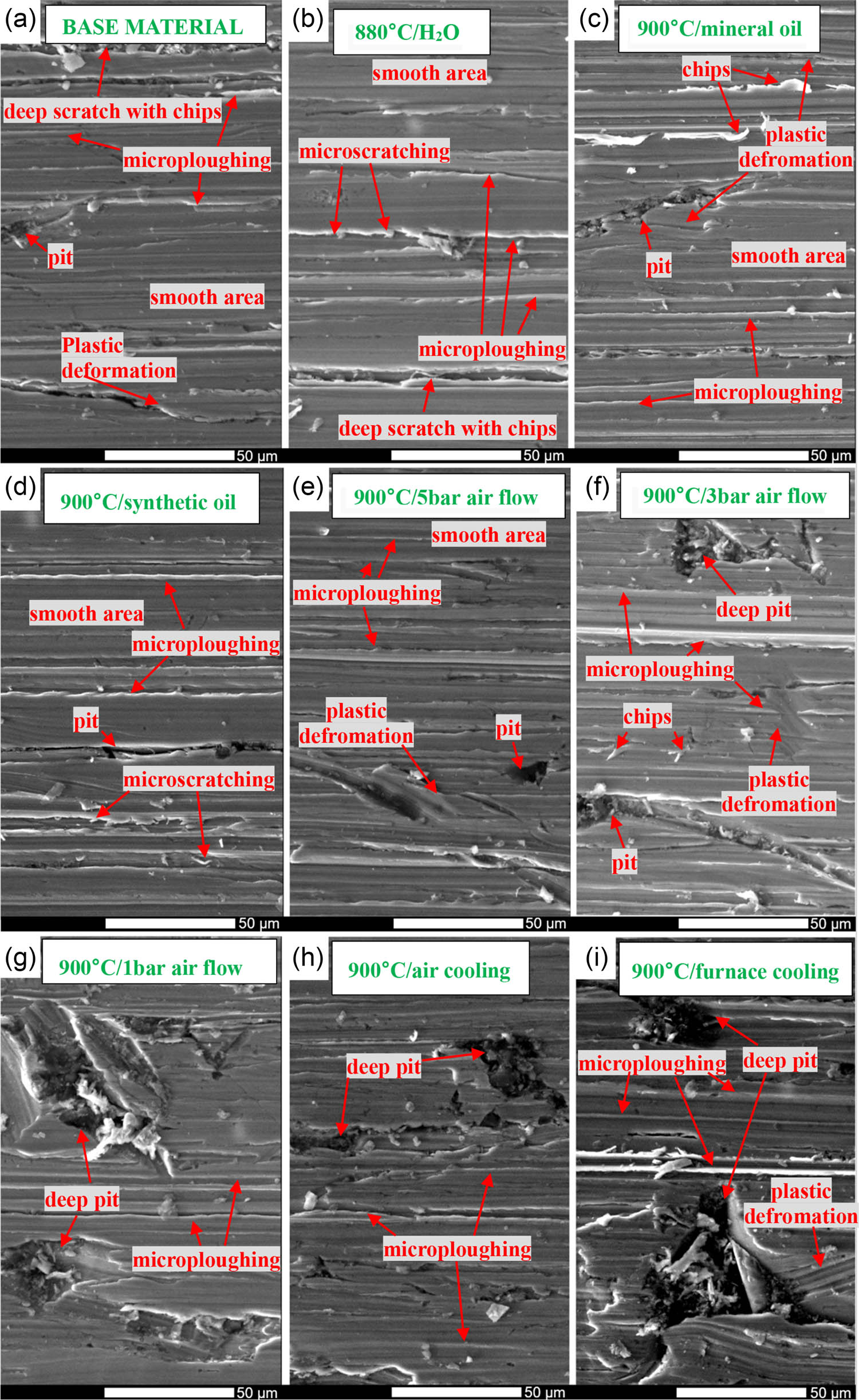
Figure 15
SEM analysis under unetched conditions of surfaces of Hardox 500 steel subjected to abrasive wear testing under different heat treatment conditions: (a) as-delivered condition, (b) after water cooling, (c) after mineral oil cooling, (d) after synthetic oil cooling, (e) after air cooling at 5 bar pressure, (f) after air cooling at 3 bar pressure, (g) after air cooling at 1 bar pressure, (h) after air cooling, and (i) after furnace cooling.
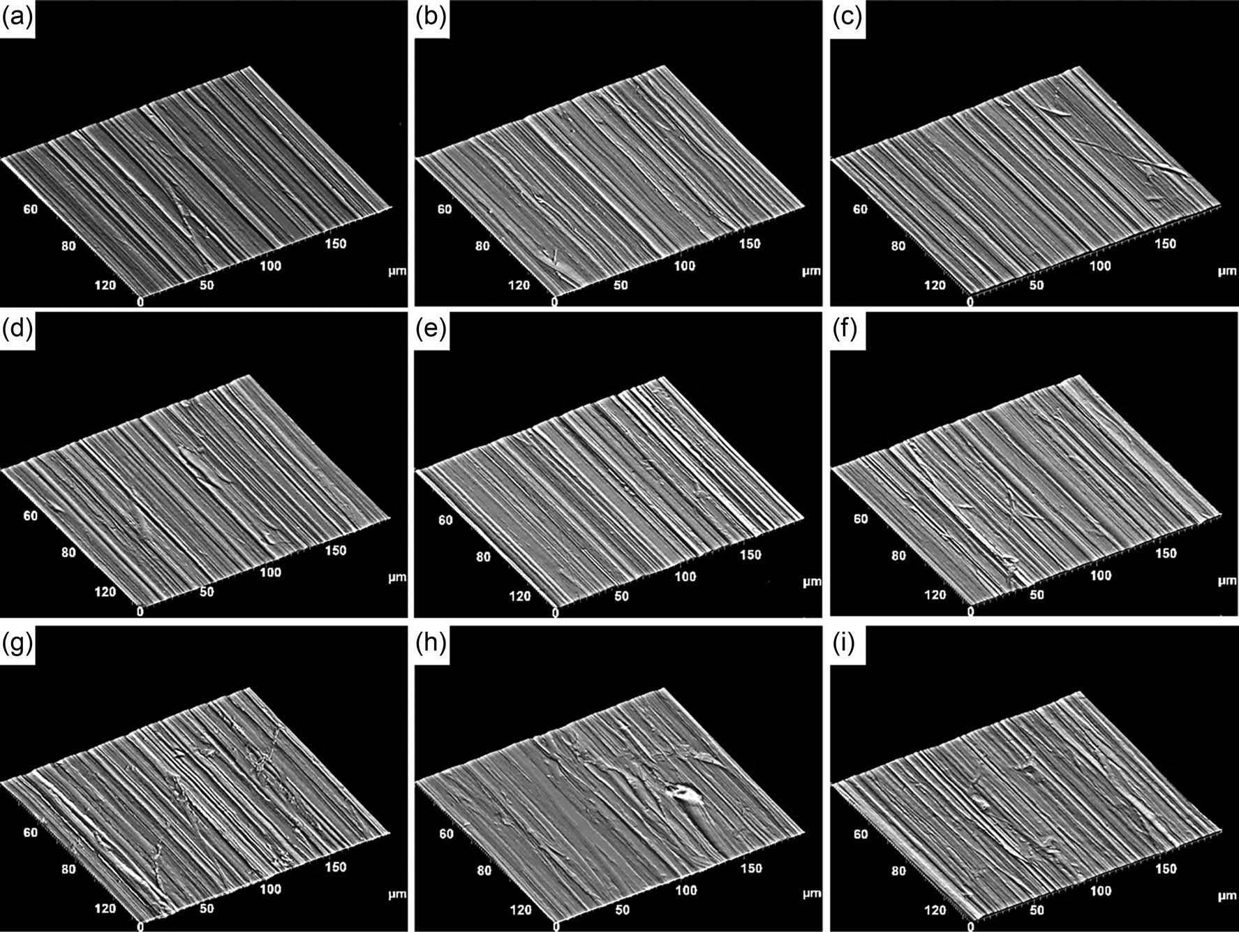
Figure 16
3D images obtained by SEM analysis of sample surfaces subjected to wear testing along the longitudinal direction of abrasive movement: (a) as-delivered condition, (b) after water cooling, (c) after mineral oil cooling, (d) after synthetic oil cooling, (e) after air cooling at 5 bar pressure, (f) after air cooling at 3 bar pressure, (g) after air cooling at 1 bar pressure, (h) after air cooling, and (i) after furnace cooling.
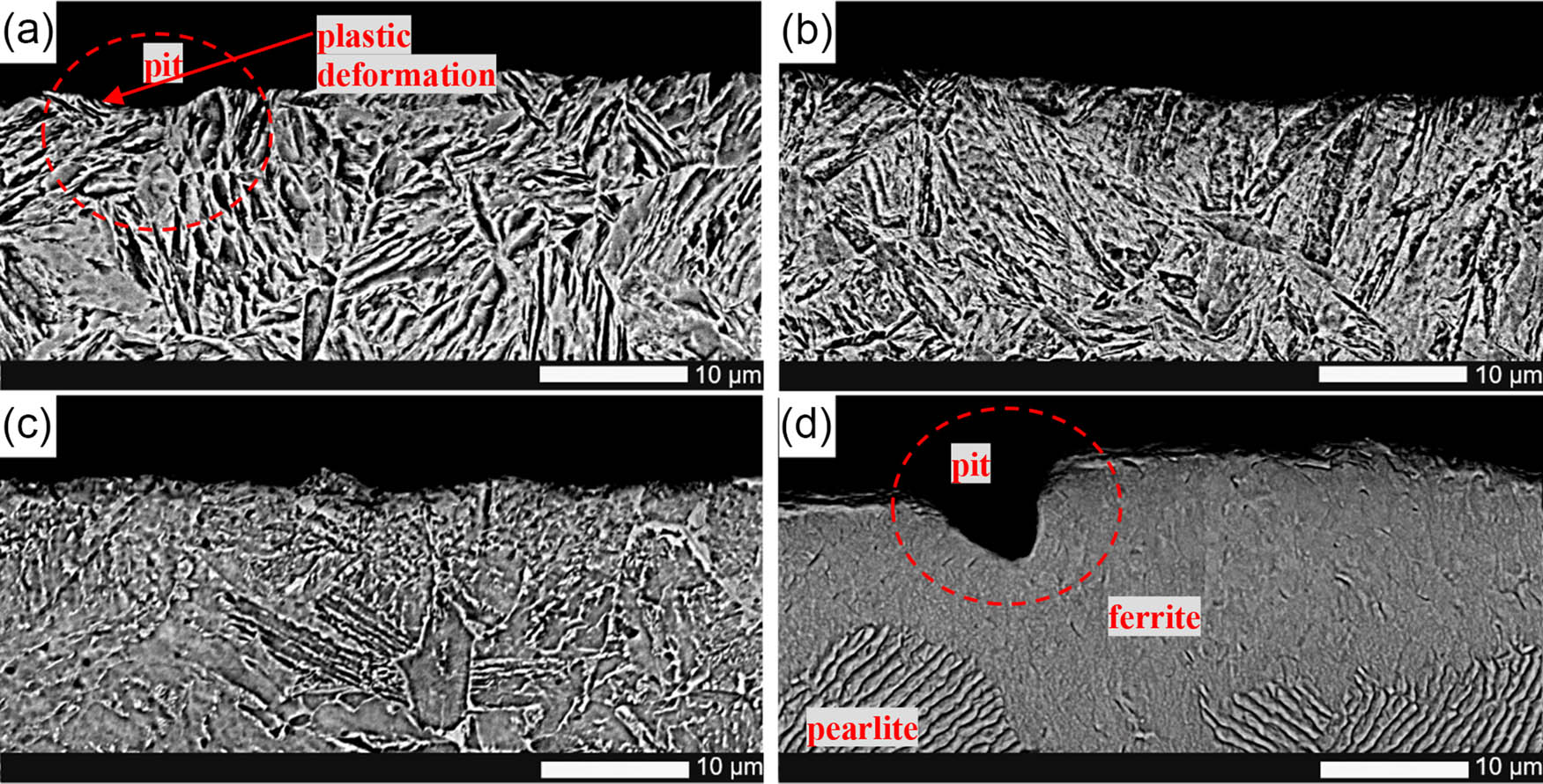
Figure 17
Cross-sectional SEM analysis under unetched conditions of selected samples subjected to abrasive wear: (a) as-delivered condition, (b) after mineral oil cooling, (c) after air cooling at 1 bar pressure, and (d) after furnace cooling.
Table 7
Results of variance analysis.
| Effect SS | Effect df | Effect MS | Error SS | Error df | Error MS | F | p | |
|---|---|---|---|---|---|---|---|---|
| R a | 0.1072 | 8 | 0.0134 | 0.1407 | 18 | 0.0078 | 1.7140 | 0.1629 |
| R p | 0.9911 | 8 | 0.1239 | 4.6533 | 18 | 0.2585 | 0.4792 | 0.8551 |
| R v | 4.4831 | 8 | 0.5604 | 3.9031 | 18 | 0.2168 | 2.5844 | 0.0450 |
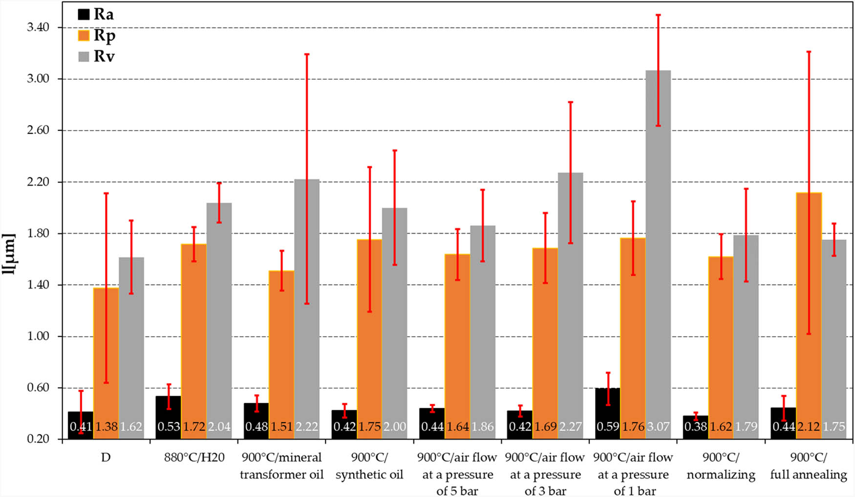
Figure 18
Roughness parameters R a, R p, and R v of Hardox 500 steel under different heat treatment conditions subjected to abrasive wear testing.
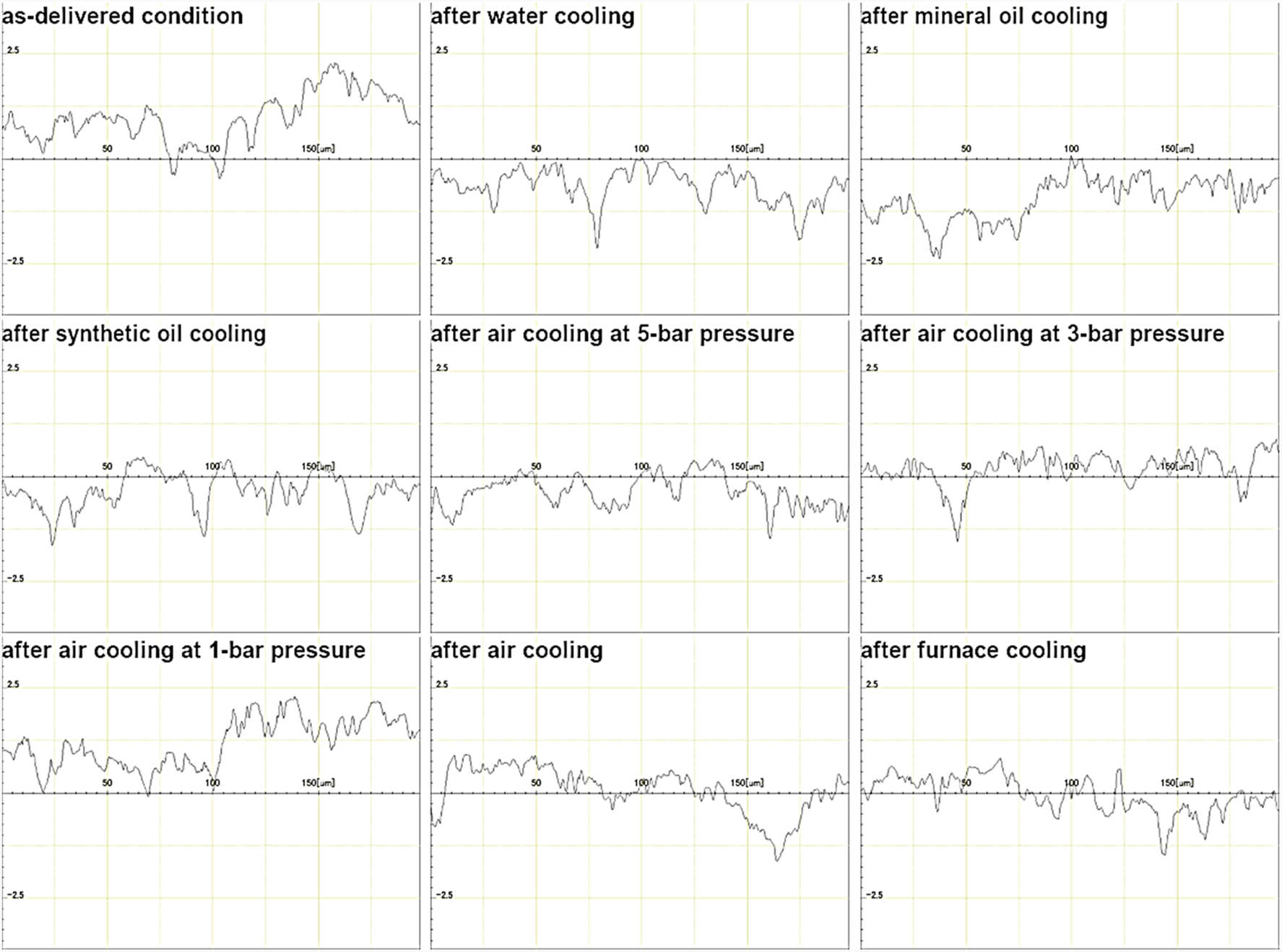
Figure 19
Profilograms of Hardox 500 steel under different heat treatment conditions subjected to abrasive wear testing.
Table 8
Results of Duncan’s test for the parameter R v.
| State of heat treatment | {1} M = 1.6167 | {2} M = 2.0367 | {3} M = 2.2233 | {4} M = 2.0000 | {5} M = 1.8600 | {6} M = 2.2733 | {7} M = 3.0667 | {8} M = 1.7867 | {9} M = 1.7533 |
|---|---|---|---|---|---|---|---|---|---|
| {1} | 0.3384 | 0.1759 | 0.3759 | 0.5651 | 0.1470 | 0.0034 | 0.6780 | 0.7236 | |
| {2} | 0.3384 | 0.6295 | 0.9243 | 0.6662 | 0.5640 | 0.0215 | 0.5545 | 0.5109 | |
| {3} | 0.1759 | 0.6295 | 0.5860 | 0.3924 | 0.8970 | 0.0488 | 0.3146 | 0.2855 | |
| {4} | 0.3759 | 0.9243 | 0.5860 | 0.7171 | 0.5185 | 0.0197 | 0.6028 | 0.5598 | |
| {5} | 0.5651 | 0.6662 | 0.3924 | 0.7171 | 0.3405 | 0.0103 | 0.8493 | 0.7944 | |
| {6} | 0.1470 | 0.5640 | 0.8970 | 0.5185 | 0.3405 | 0.0516 | 0.2694 | 0.2426 | |
| {7} | 0.0034 | 0.0215 | 0.0488 | 0.0197 | 0.0103 | 0.0516 | 0.0075 | 0.0067 | |
| {8} | 0.6780 | 0.5545 | 0.3146 | 0.6028 | 0.8493 | 0.2694 | 0.0075 | 0.9312 | |
| {9} | 0.7236 | 0.5109 | 0.2855 | 0.5598 | 0.7944 | 0.2426 | 0.0067 | 0.9312 |