
Table 1
304L and 316L SS chemical composition (%).
| Substrate | C | Mn | P | S | Si | Cr | Ni | Mo | Fe% |
|---|---|---|---|---|---|---|---|---|---|
| SS 304L | 0.030 | 2.00 | 0.45 | 0.03 | 1.00 | 18.0–20.0 | 8.00–12.00 | — | Bal. |
| SS 316L | 0.030 | 2.00 | 0.45 | 0.03 | 1.00 | 16.0–18.0 | 10.00–14.00 | 2.00–3.00 | Bal. |
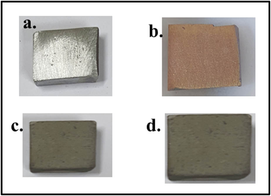
Figure 1
Macrographs of specimens. (a) Uncoated AISI 304L steel substrate. (b) Uncoated AISI 316L steel substrate. (c) Cr3C2–25% NiCr-coated AISI 304L steel substrate. (d) Cr3C2–25% NiCr-coated AISI 316L steel substrate.
Table 2
Powder coating process parameters.
| Parameters | Cr3C2–NiCr coating |
|---|---|
| Proportion | 75% Cr3C2/25% NiCr |
| Oxygen flow rate (O2) | 2720 SLPH |
| Acetylene (C2H2) flow rate | 2320 SLPH |
| Pressure (P) | 0.2 MPa |
| Nitrogen flow rate (N2) | 720 SLPH |
| Pressure (P) | 0.14 MPa |
| Power | 450 VA |
| Spray distance | 165 mm |
| Spray angle | 90o |
| Coating thickness (average) | 450 µm |
| Fire rate | 10 Hz (10 shots per second) |
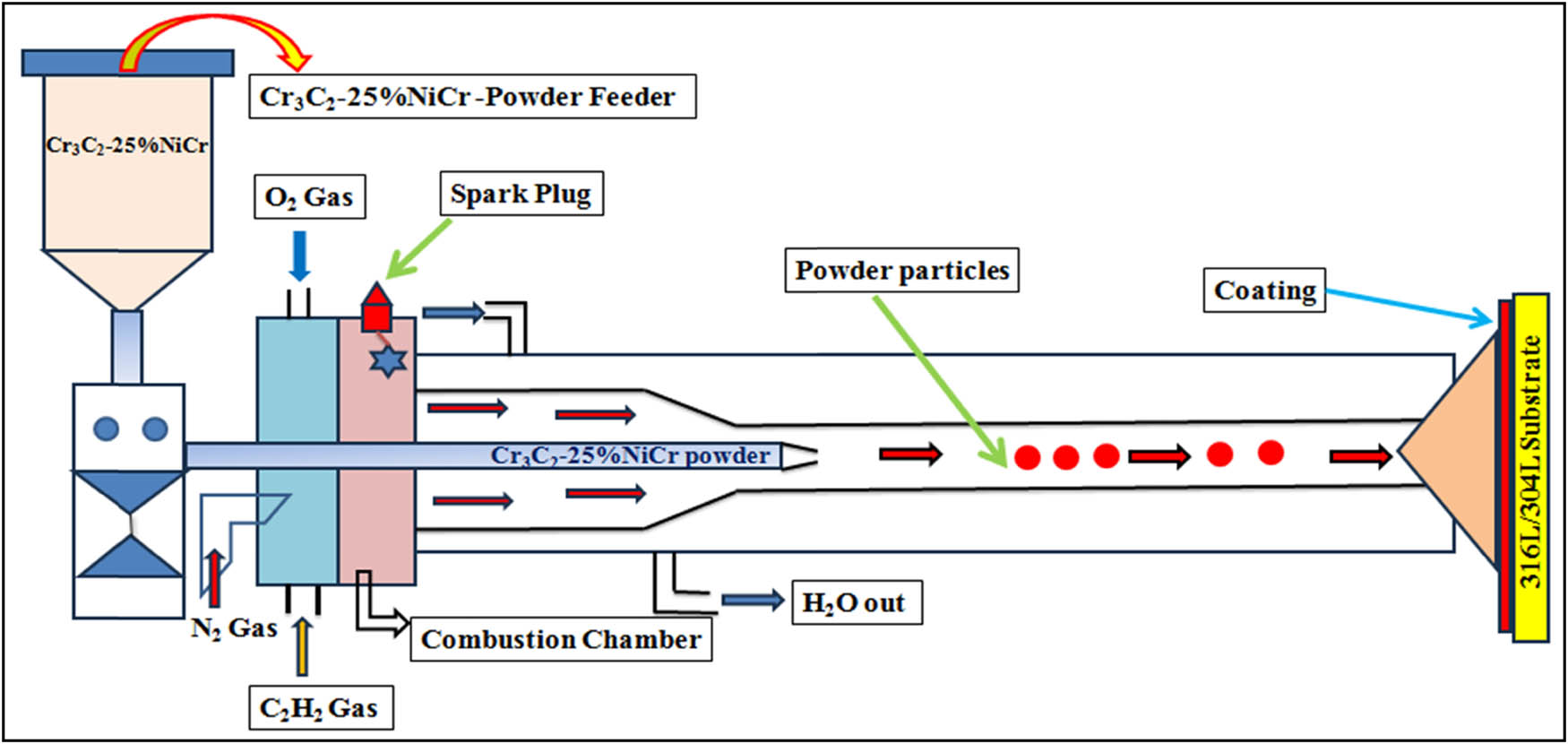
Figure 2
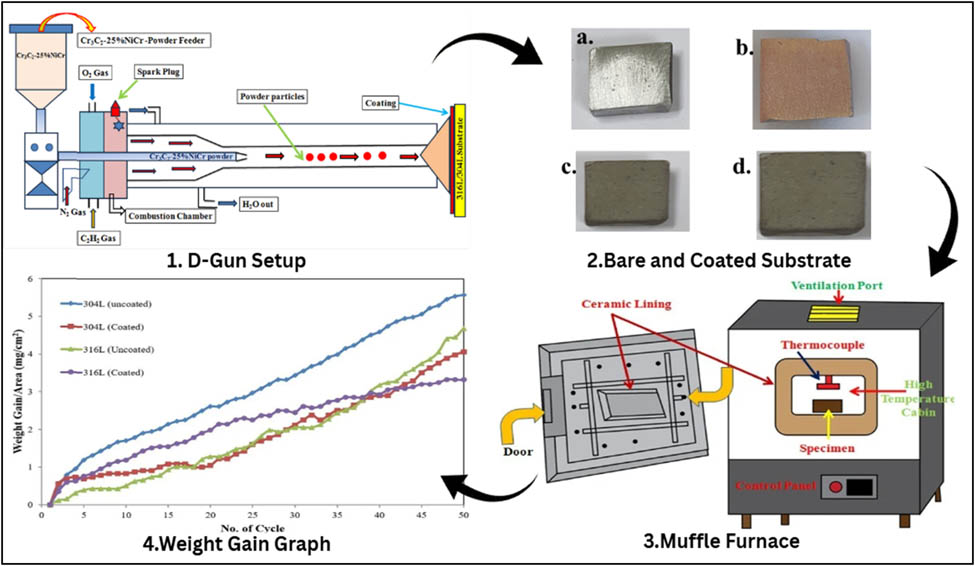
Schematic diagram of the D-gun method.
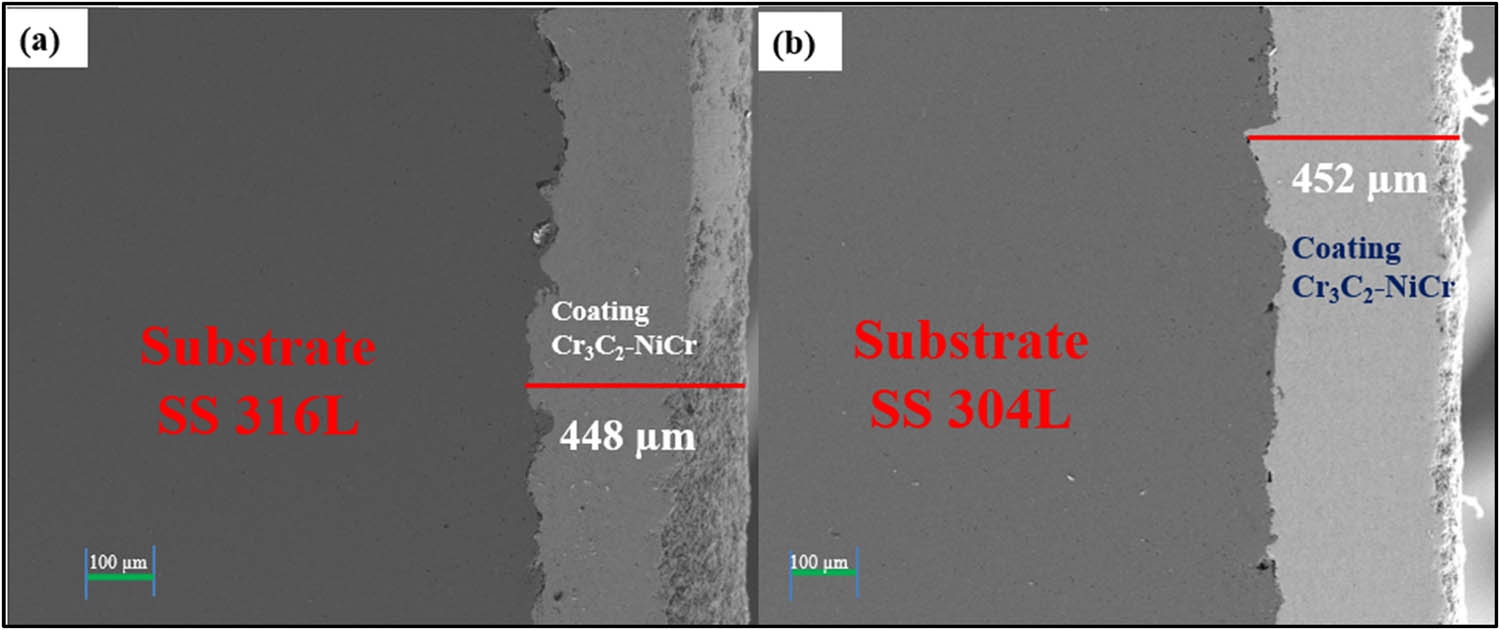
Figure 3
Coating thickness: (a) substrate SS 316L and (b) substrate SS 304L.
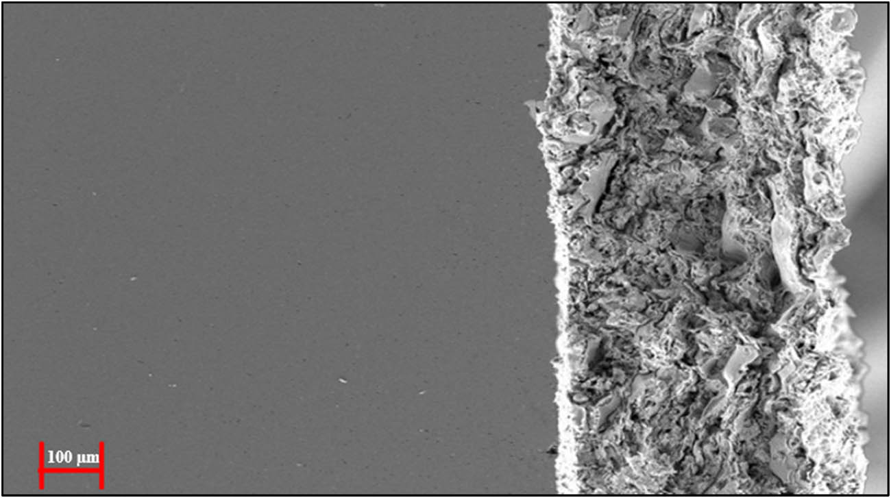
Figure 4
Cross-section SEM image after oxidation.
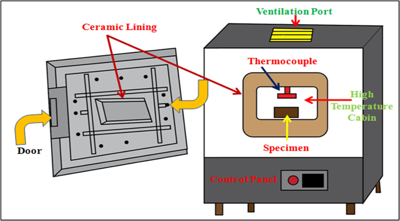
Figure 5
Schematic diagram of the muffle furnace.
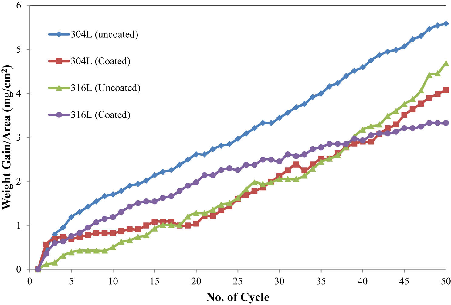
Figure 6
Weight gain/area vs the number of cycles for bare and coated 304L and SS 316L in dry air at 850°C.
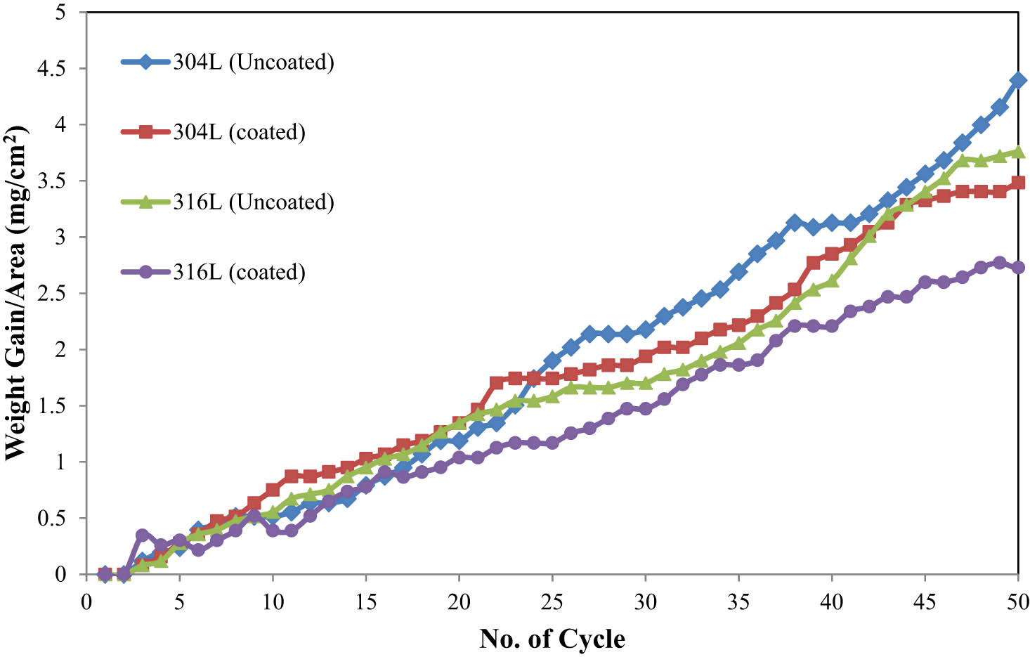
Figure 7
Weight gain/area vs the number of cycles for bare and coated SS 304L and SS 316L in dry air at 750°C.
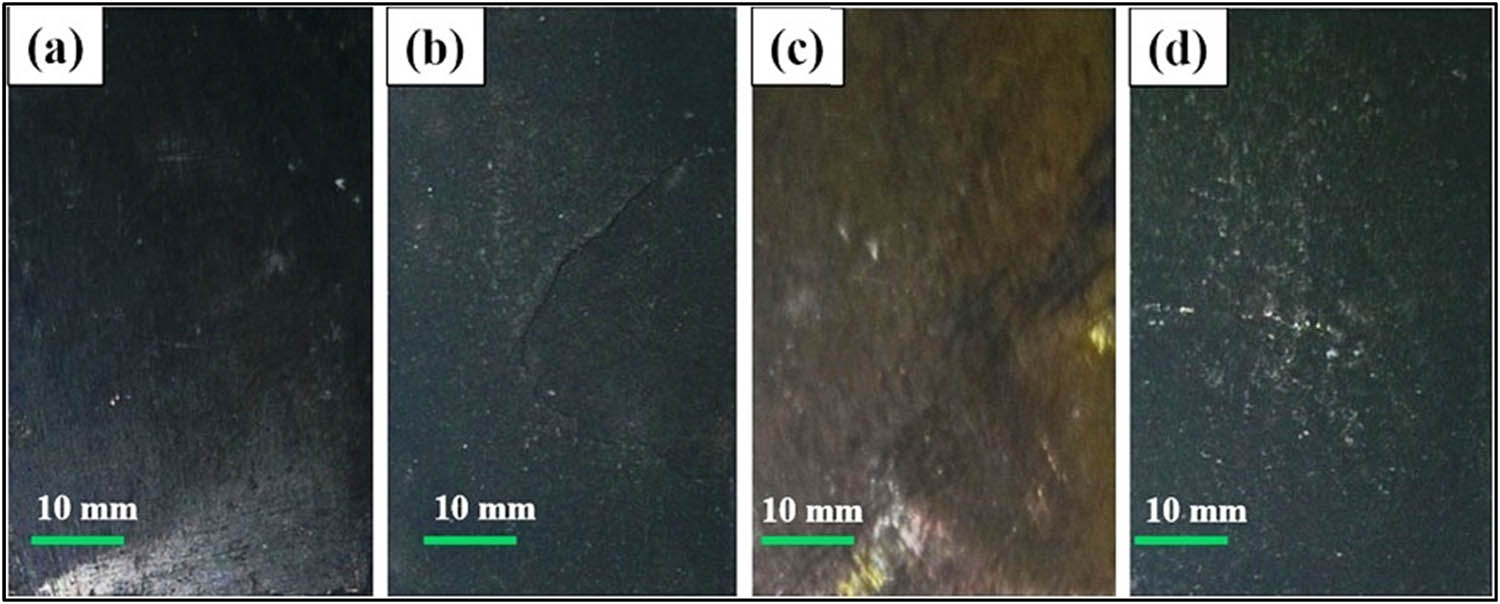
Figure 8
Macrographs of specimens in dry air at 850°C. (a) Uncoated 304L. (b) Coated 304L. (c) Uncoated 316L. (d) Coated 316L.
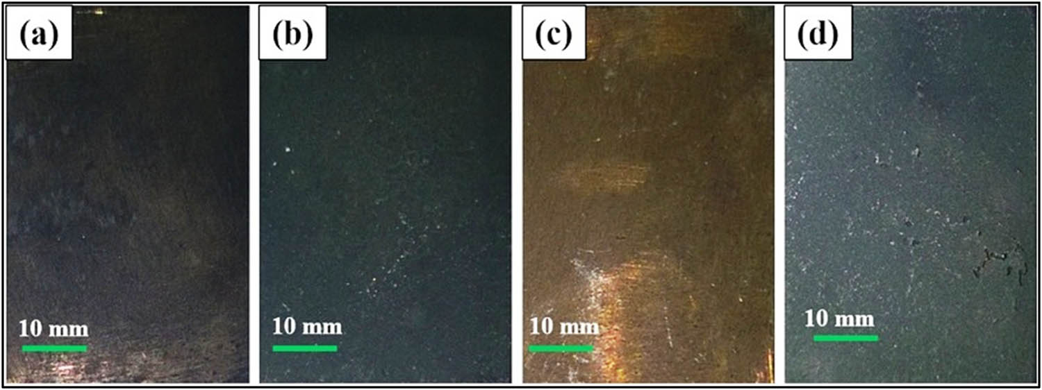
Figure 9
Macrographs of specimens in dry air at 750°C. (a) Uncoated 304L. (b) Coated 304L. (c) Uncoated 316L. (d) Coated 316L.
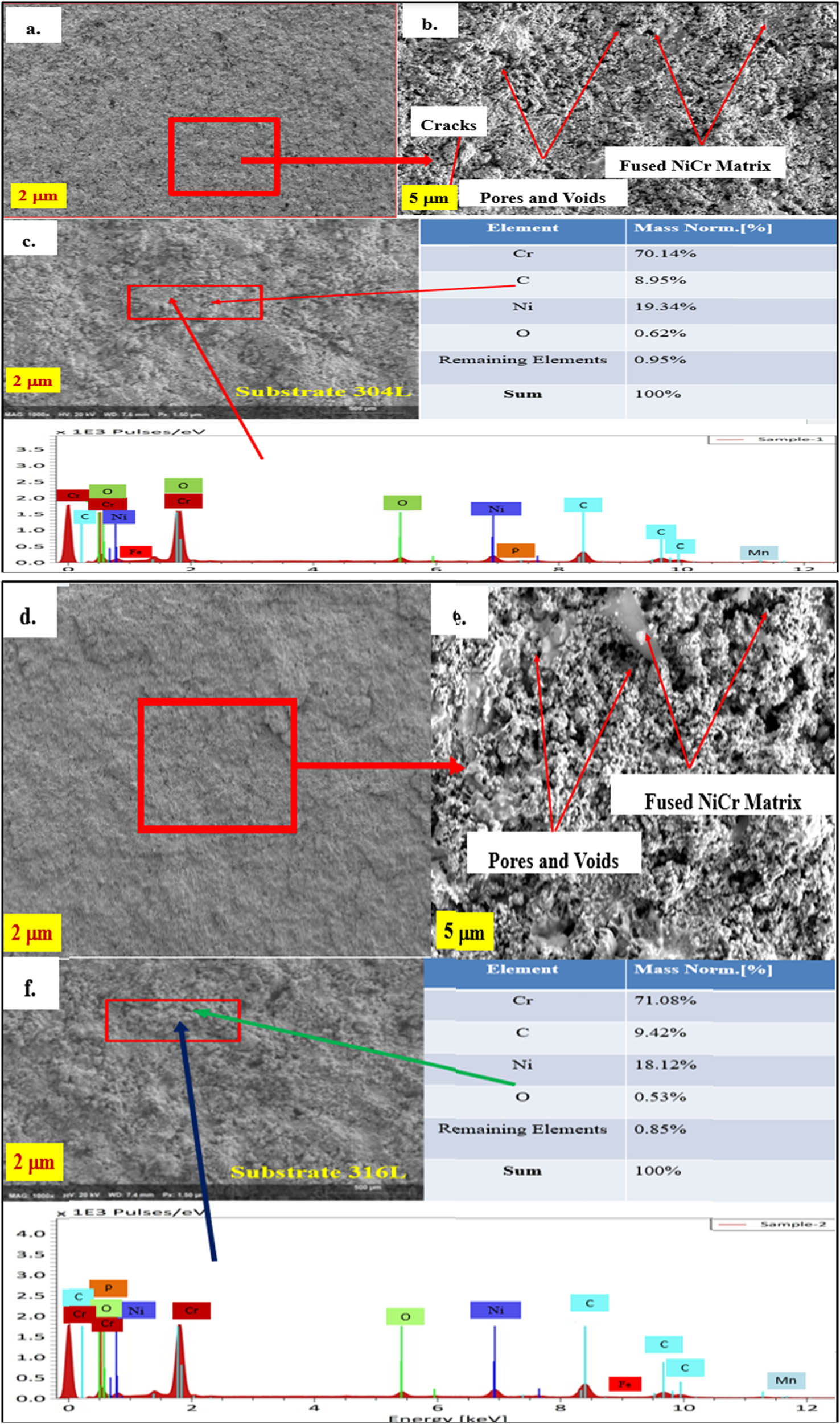
Figure 10
SEM images of Cr3C2–NiCr-coated (a–c) SS 304L and (d–f) SS 316L.
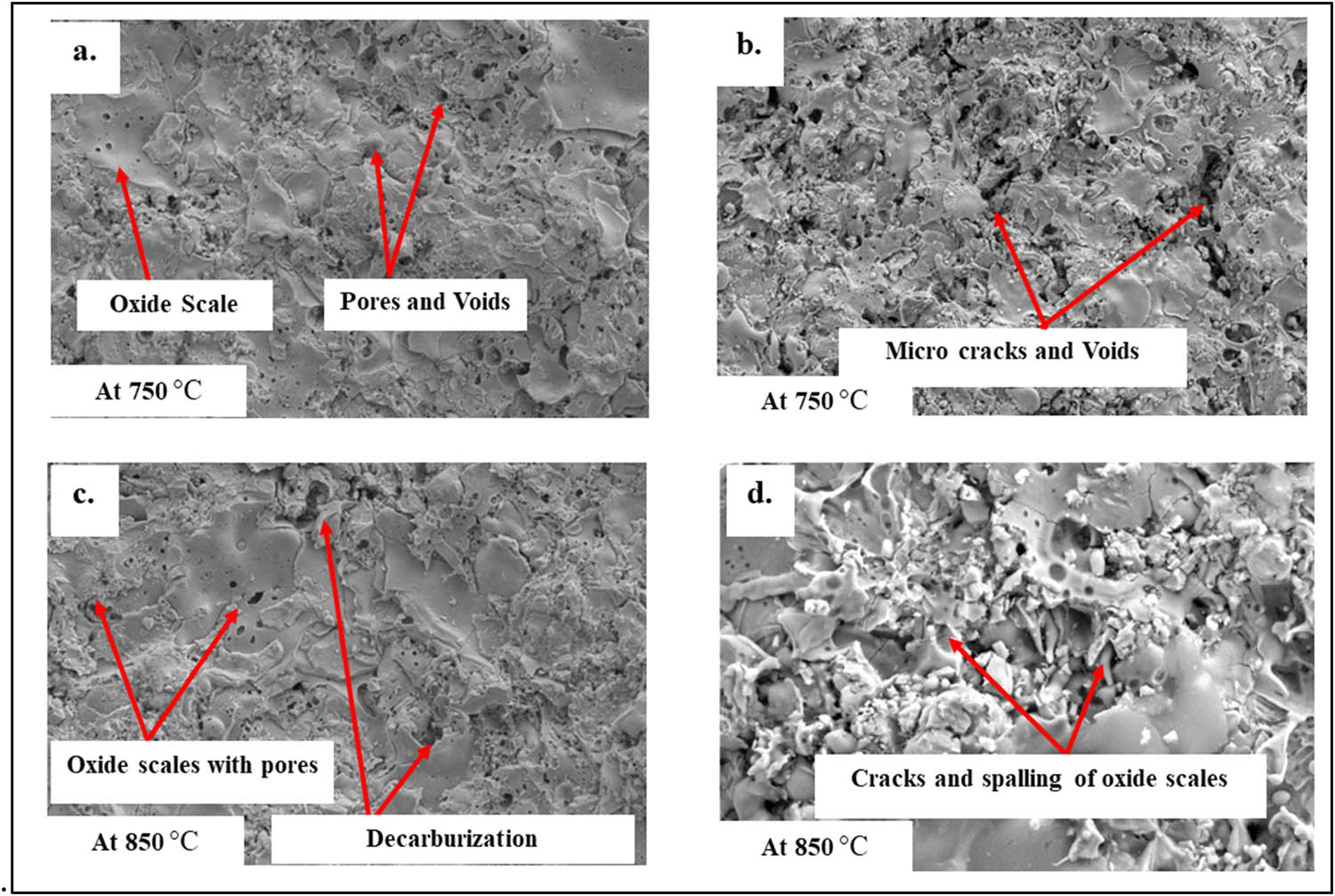
Figure 11
SEM images of Cr3C2–NiCr coated (a) SS 304L at 750°C, (b) SS 316L at 750°C, (c) SS 304L at 850°C, and (d) SS 316L at 850°C after the oxidation cycle.
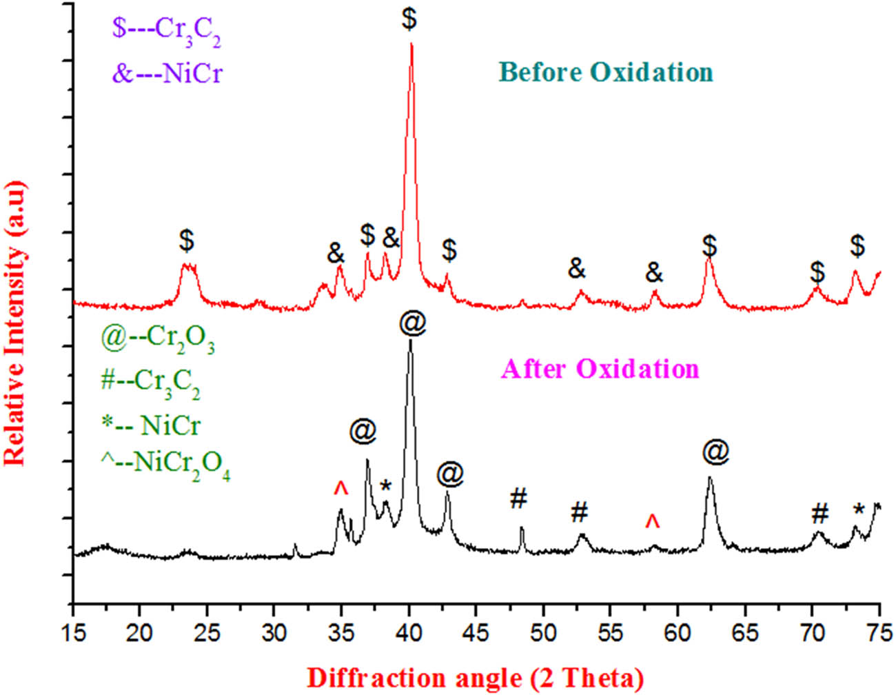
Figure 12
XRD patterns of as-sprayed and oxidized coatings.