
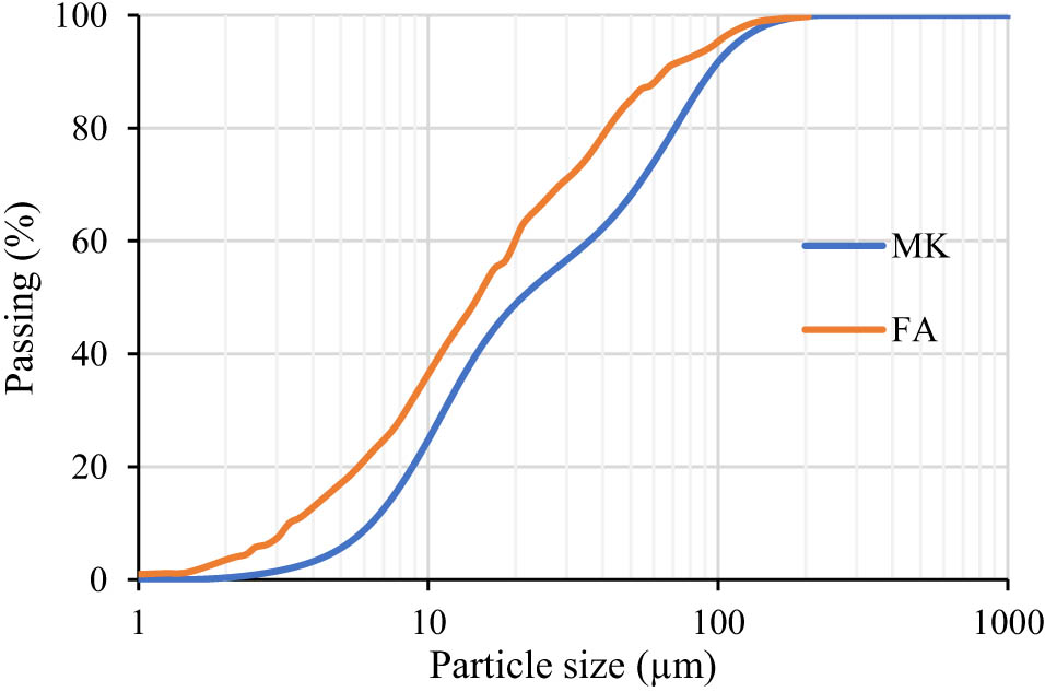
Figure 1
Particle size of MK and FA utilized in this investigation.
Table 1
MK’s chemical analysis (% weight).
| Composition | SiO2 | CaO | Fe2O3 | Na2O | Al2O3 | TiO2 | SO3 | K2O | P2O5 | MgO | Others |
|---|---|---|---|---|---|---|---|---|---|---|---|
| Value (%) | 50.995 | 1.287 | 2.114 | 0.284 | 42.631 | 1.713 | 0.439 | 0.337 | 0.051 | 0.127 | 0.022 |
| 61.30 | 0.28 | 4.39 | 0.12 | 24.80 | 0.80 | 0.39 | 1.49 | 0.45 | 0.74 | 5.26 |
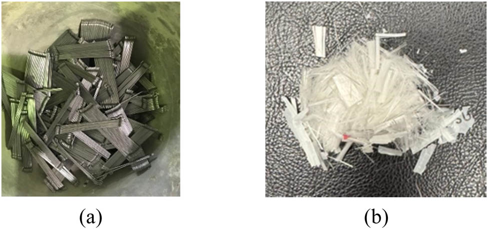
Figure 2
Fiber types: (a) SF and (b) PVA.
Table 2
Fiber characteristics.
| Properties | Fiber | |
|---|---|---|
| SF | PVA | |
| Shape | Hooked ends (circular cross section) | Straight (circular cross section) |
| Diameter (mm) | 0.75 | 0.06 |
| Length (mm) | 60 | 12 |
| Aspect ratio | 80 | 200 |
| Tensile strength (MPa) | 1,225 | 1,600 |
| Young’s modulus (MPa) | 200,000 | 35,000 |
| Density (kg/m3) | 7,850 | 1,300 |
Table 3
GPC mixture proportions in kg/m3.
| Material | Weight | |
|---|---|---|
| MK | 277.2 | |
| FA | 118.8 | |
| NaOH solution | 92 | |
| Na2SiO3 solution | 291.3 | |
| Fine aggregate Crushed limestone (max size: 4.75 mm) | 449.8 | |
| White sand (max size: 2 mm) | 148.4 | |
| Coarse aggregate Crushed limestone, max size: 10 mm) | 1365.8 | |
Table 4
Test matrix utilized in the experimental scheme of the current study.
| Mixture ID | Specimens ID | Temperatures (°C) | Fiber volume | No. of specimens | ||
|---|---|---|---|---|---|---|
| SF | PVA | Total | ||||
| M0 | M-25 | 25 | — | — | — | 3 |
| M-300 | 300 | 3 | ||||
| M-500 | 500 | 3 | ||||
| MS | MS-25 | 25 | 1% | — | 1% | 3 |
| MS-300 | 300 | 3 | ||||
| MS-500 | 500 | 3 | ||||
| MSP | MSP-25 | 25 | 0.7% | 0.3% | 1% | 3 |
| MSP-300 | 300 | 3 | ||||
| MSP-500 | 500 | 3 | ||||
| Total no. of specimens | 27 | |||||
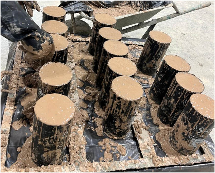
Figure 3
GPC cylindrical specimens during casting.
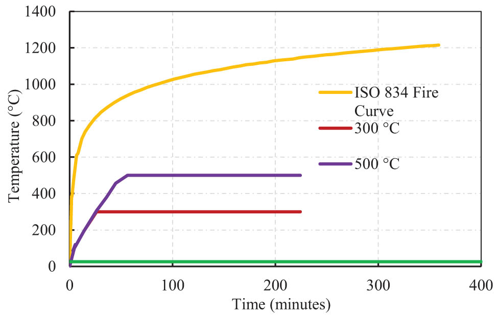
Figure 4
Time–temperature curves of GPC cylinders used in the current study.
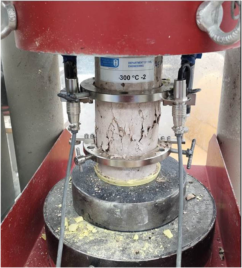
Figure 5
Test setup used in the current study.
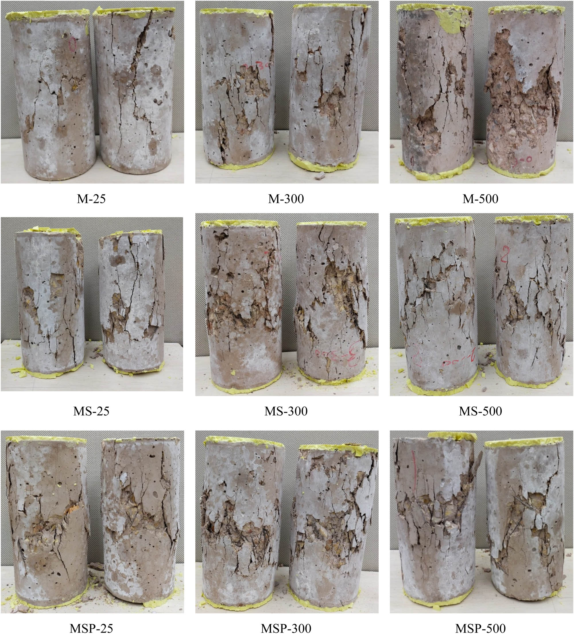
Figure 6
Failure modes of representative specimens.
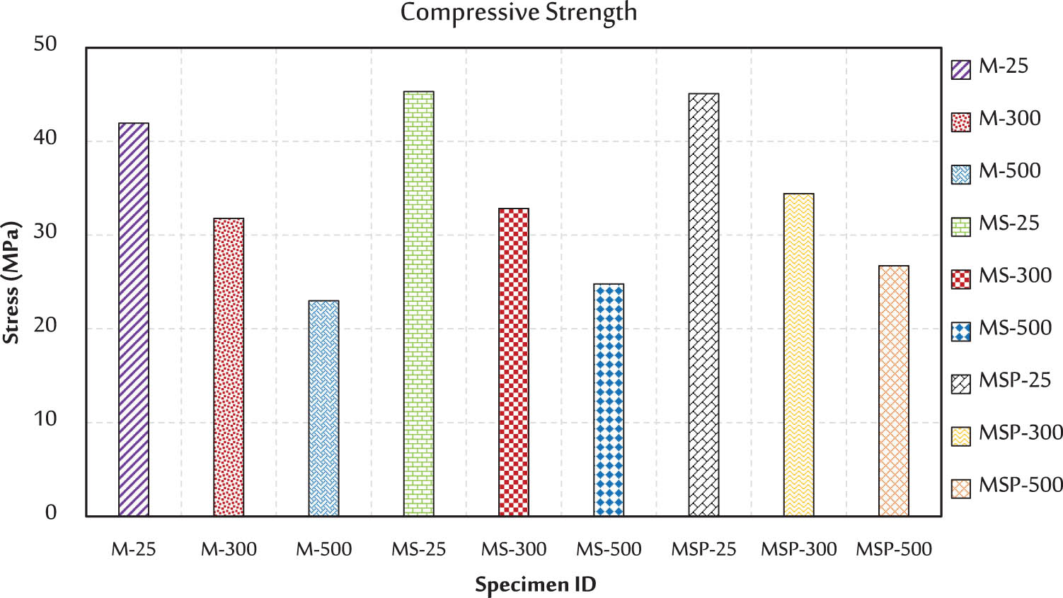
Figure 7
Compressive strength of all specimens.
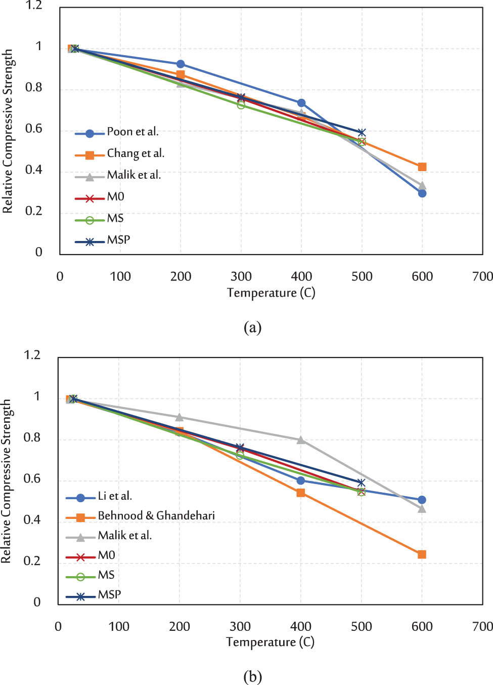
Figure 8
Relative compressive strength: (a) normal strength concrete [36,38,39] and (b) high strength concrete [36,37,40].
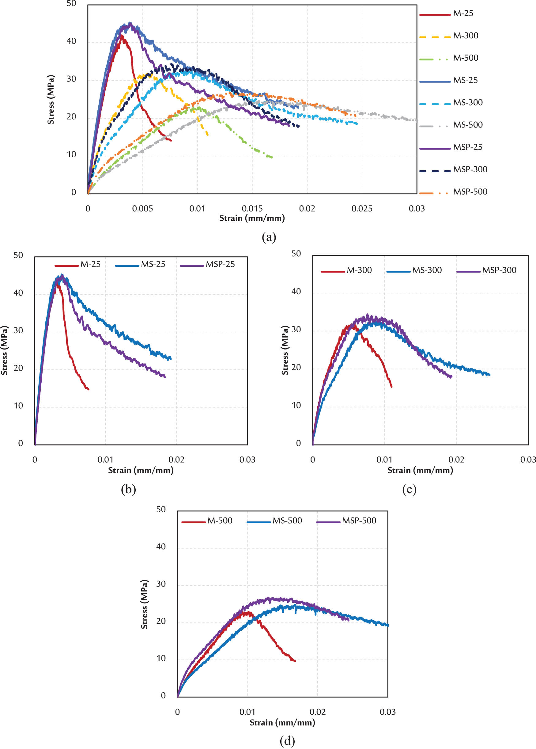
Figure 9
Stress–strain curves: (a) all specimens, (b) specimens at 25°C, (c) specimens at 300°C, and (d) specimens at 500°C.
Table 5
Summary of test results.
| Specimens | Compressive strength (MPa) | Relative difference (%)a | Initial stiffness (N/mm) | Relative difference (%)a | Toughness index (%) | Relative difference (%)a |
|---|---|---|---|---|---|---|
| M-25 | 41.94 | — | 19,853.3 | — | 2.38 | — |
| M-300 | 31.79 | 24.2 | 11,560.0 | 41.8 | 1.77 | 25.3 |
| M-500 | 23.00 | 45.2 | 31,88.9 | 83.9 | 1.38 | 41.9 |
| MS-25 | 45.32 | — | 23,696.7 | — | 2.91 | — |
| MS-300 | 32.85 | 27.5 | 7,300.0 | 69.2 | 2.25 | 22.8 |
| MS-500 | 24.80 | 45.3 | 2,387.5 | 89.9 | 1.87 | 35.7 |
| MSP-25 | 45.10 | — | 19,933.7 | — | 3.07 | — |
| MSP-300 | 34.44 | 23.6 | 10,933.3 | 45.2 | 2.19 | 28.5 |
| MSP-500 | 26.73 | 40.7 | 4,096.6 | 79.4 | 1.78 | 41.9 |
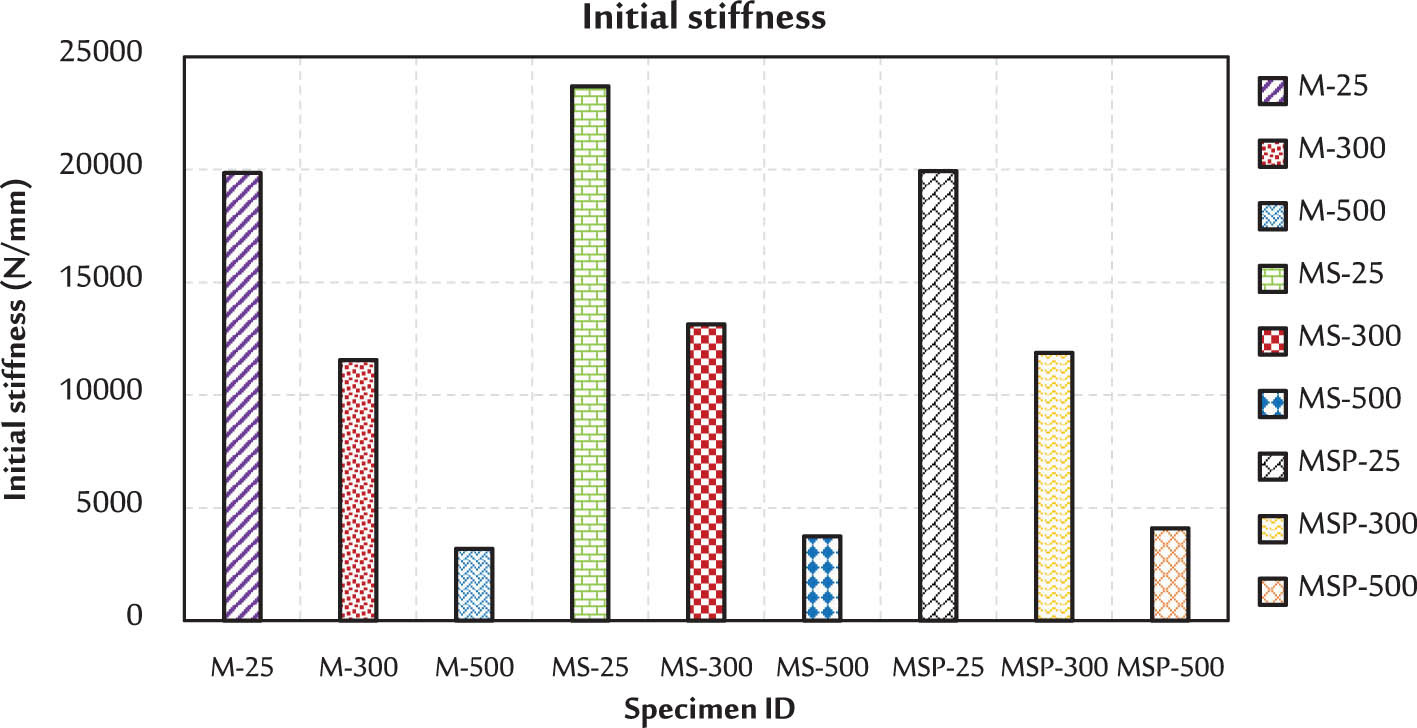
Figure 10
Initial stiffness of all specimens.
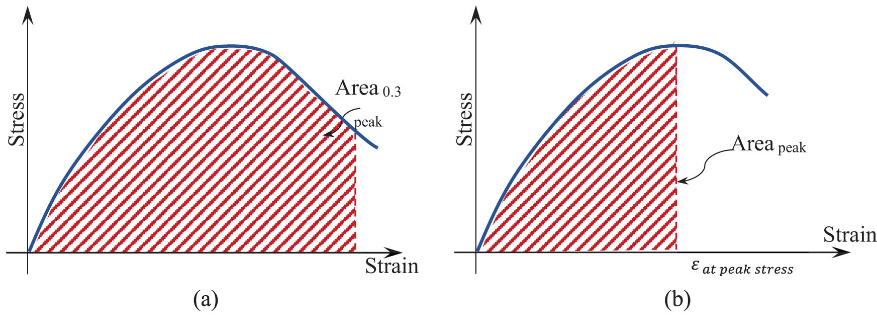
Figure 11
Initial stiffness of all specimens: (a) the area under the curve until 0.3 peak stress (in the decreased portion) and (b) the area under the curve until peak stress.
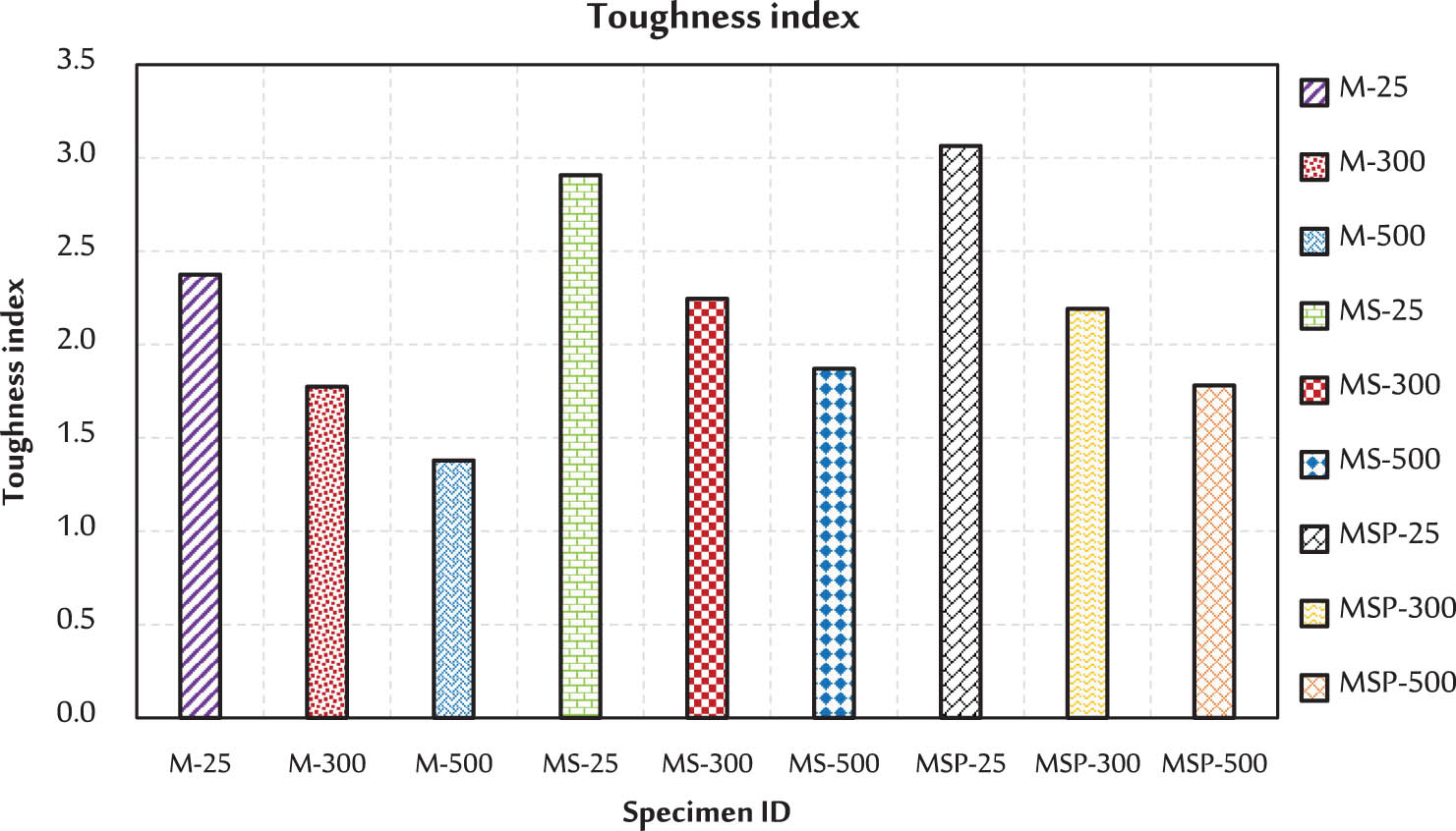
Figure 12
Toughness index of all specimens.