
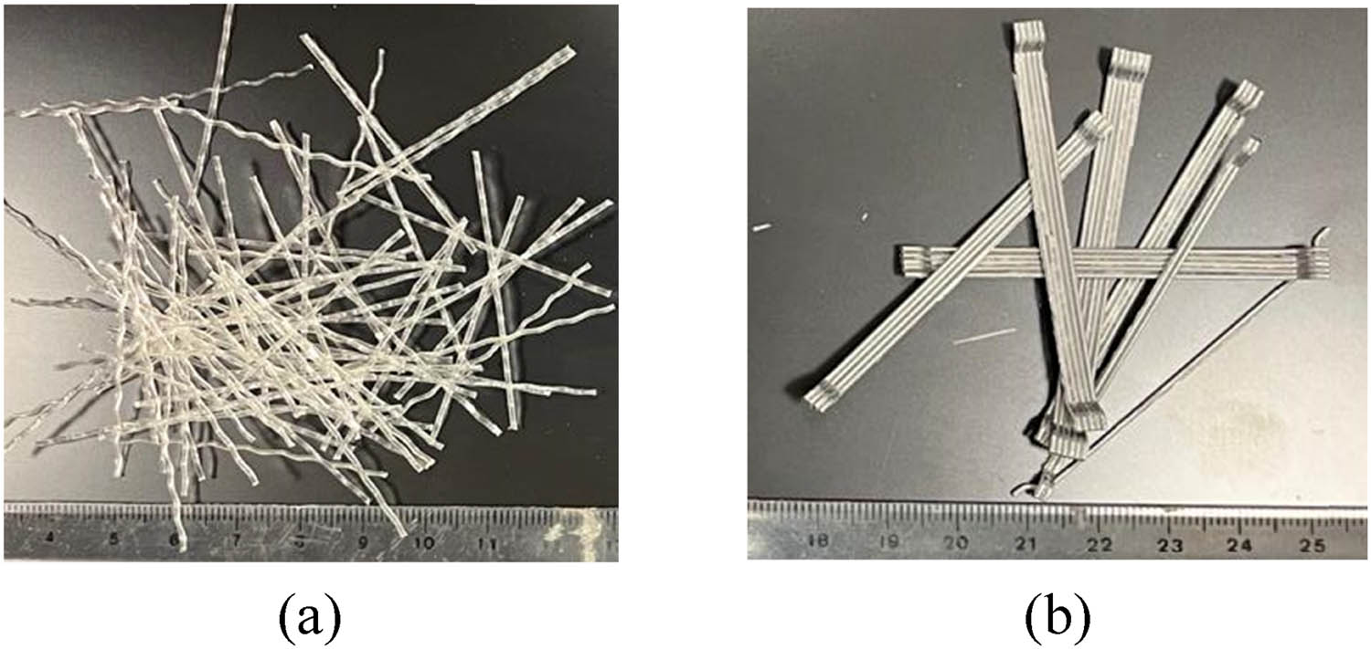
Figure 1
The fiber types: (a) PPF and (b) SF.
Table 1
Fiber characteristics.
| Properties | Fiber | |
|---|---|---|
| PPF | SF | |
| Shape | Crimped | Hooked ends |
| Section dimensions (mm) | 1.0 × 0.6 (rectangular cross section) | 0.75 (circular cross section) |
| Length (mm) | 50 | 60 |
| Tensile strength (MPa) | 550 | 1225 |
| Modulus of elasticity (Gpa) | 4.0 | 200 |
| Specific gravity | 0.90 | 7.85 |
Table 2
Epoxy adhesive and CFRP strip properties.
| Material | Property | Value | Notes |
|---|---|---|---|
| CFRP strip | Tensile Young’s modulus | 68.9 GPa | Experimental values |
| Thickness | 1.0 mm | ||
| Tensile strength | 1122 MPa | ||
| Tensile strain | 1.7% | ||
| Epoxy adhesive | Tensile strength | 71.5 MPa | Given by the manufacturer |
| Tensile Young’s modulus | 1.86 GPa | ||
| Tensile strain at break | %5.25 |
Table 3
Concrete mixture proportions (in kg/m3).
| Material | Weight | |
|---|---|---|
| Ordinary Portland cement | 378 | |
| Water | 190.5 | |
| Silica sand | 489 | |
| Crush sand | 294 | |
| Coarse aggregate | d agg. = 20 mm | 675 |
| d agg. = 10 mm | 320 | |
| Super-plasticizer | 1.0 L | |
Table 4
Test matrix used in the experimental program of this investigation.
| Mixture ID | Specimen ID | Temperature (°C) | Fiber volume | Strengthening | No. of specimens | ||
|---|---|---|---|---|---|---|---|
| SF (%) | PPF (%) | Total (%) | |||||
| M-C0 | C0-A | 26 | — | — | — | — | 3 |
| C0-T | 600 | 3 | |||||
| C0-A-S | 26 | CFRP | 3 | ||||
| C0-T-S | 600 | 3 | |||||
| M-PPF | PPF-A | 26 | — | 0.2 | 0.2 | — | 3 |
| PPF-T | 600 | 3 | |||||
| PPF-A-S | 26 | CFRP | 3 | ||||
| PPF-T-S | 600 | 3 | |||||
| M-SF | SF-A | 26 | 0.6 | — | 0.6 | — | 3 |
| SF-T | 600 | 3 | |||||
| SF-A-S | 26 | CFRP | 3 | ||||
| SF-T-S | 600 | 3 | |||||
| M-SF + PPF | SF + PPF-A | 26 | 0.6 | 0.2 | 0.8 | — | 3 |
| SF + PPF-T | 600 | 3 | |||||
| SF + PPF-A-S | 26 | CFRP | 3 | ||||
| SF + PPF-T-S | 600 | 3 | |||||
| Total no. of specimens | 48 | ||||||
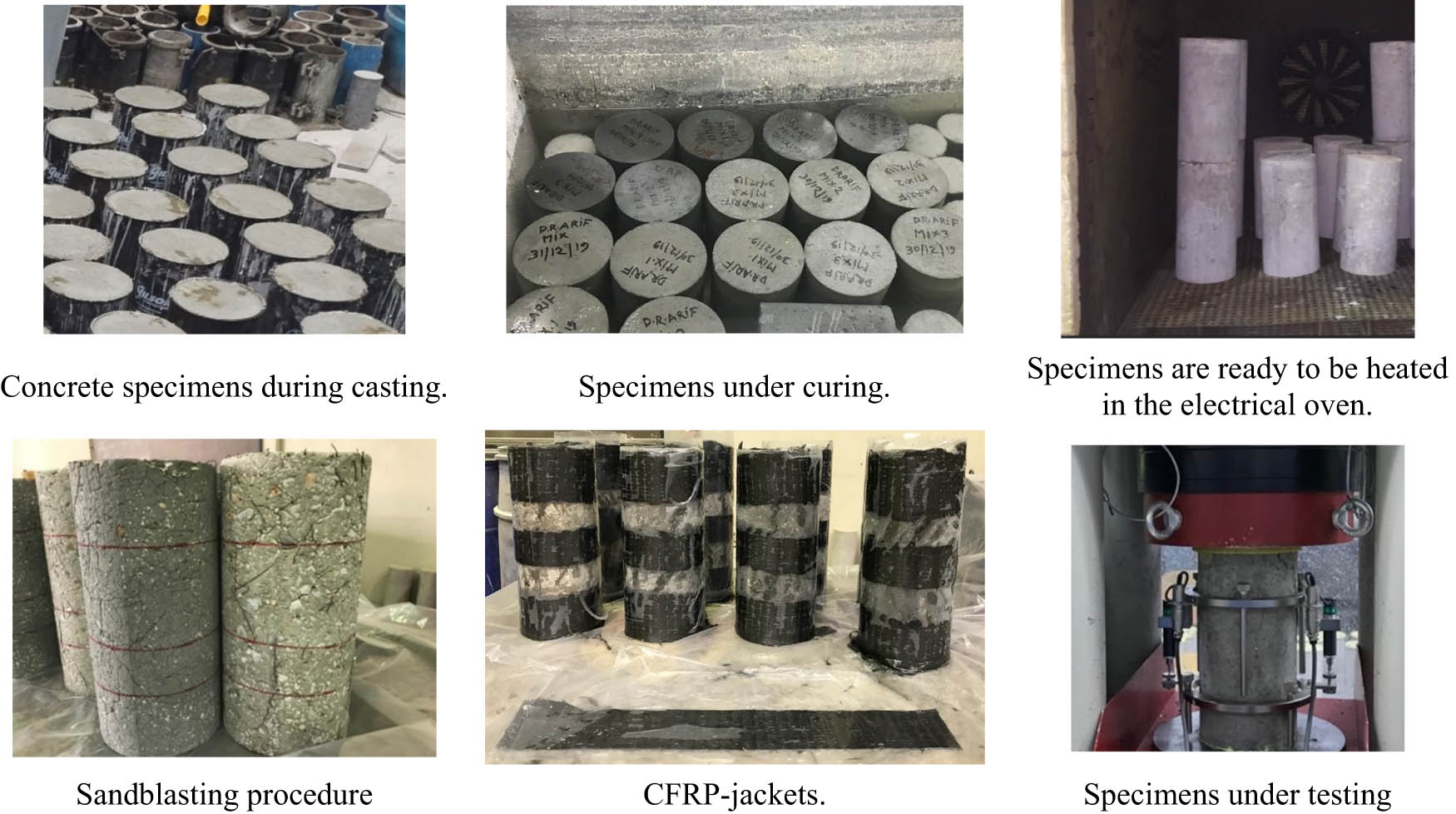
Figure 2
Methodology of experiments: casting, curing, heating, sandblasting, strengthening, and testing.
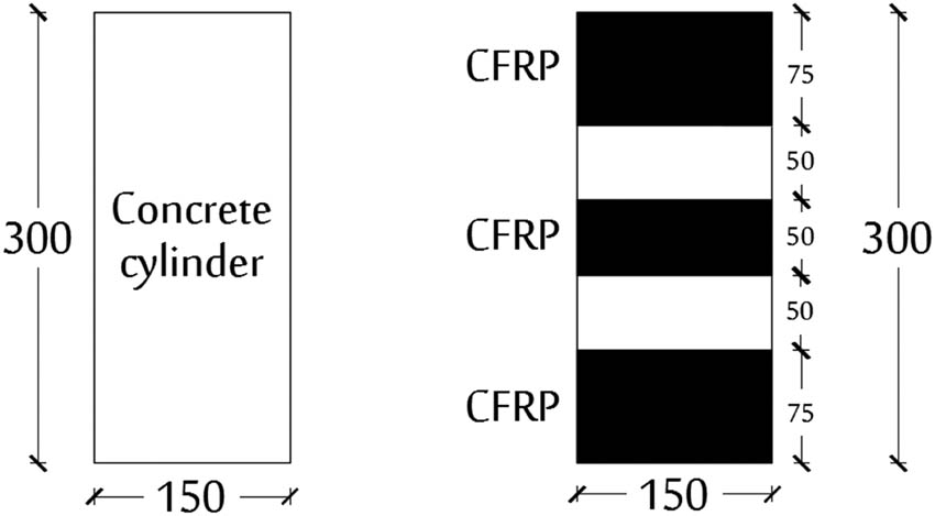
Figure 3
CFRP wrapping pattern.
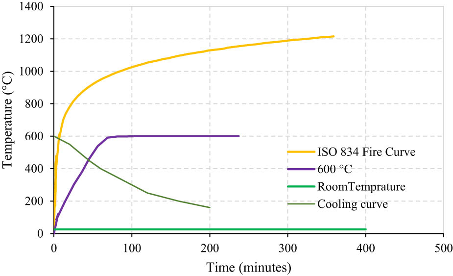
Figure 4
The heating and cooling curves used in this study.
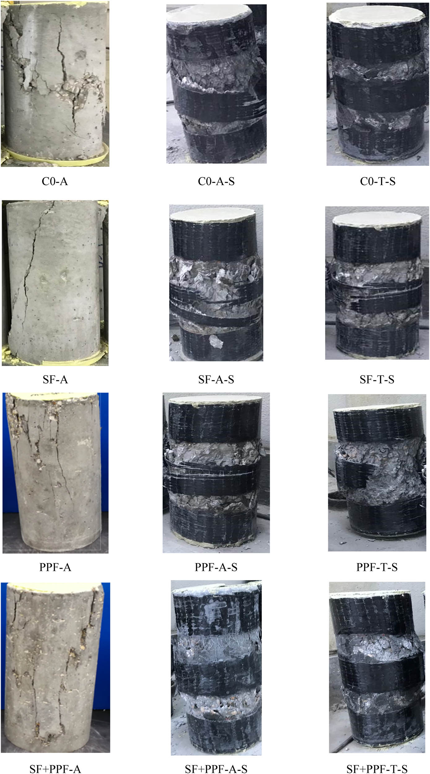
Figure 5
The failure patterns for strengthened and unstrengthened specimens.
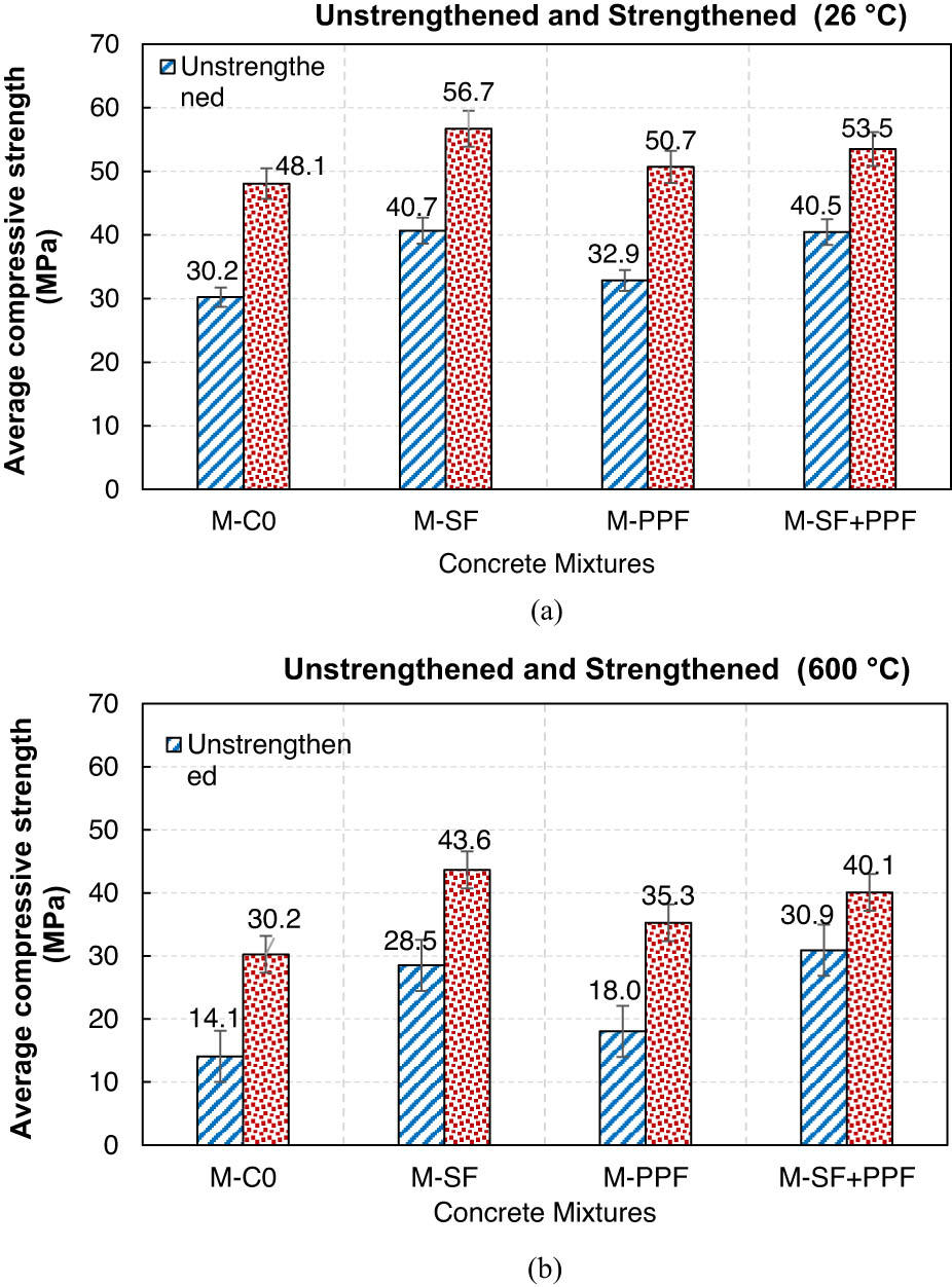
Figure 6
Effectiveness of CFRP jackets for all specimens at (a) 26°C and (b) 600°C.
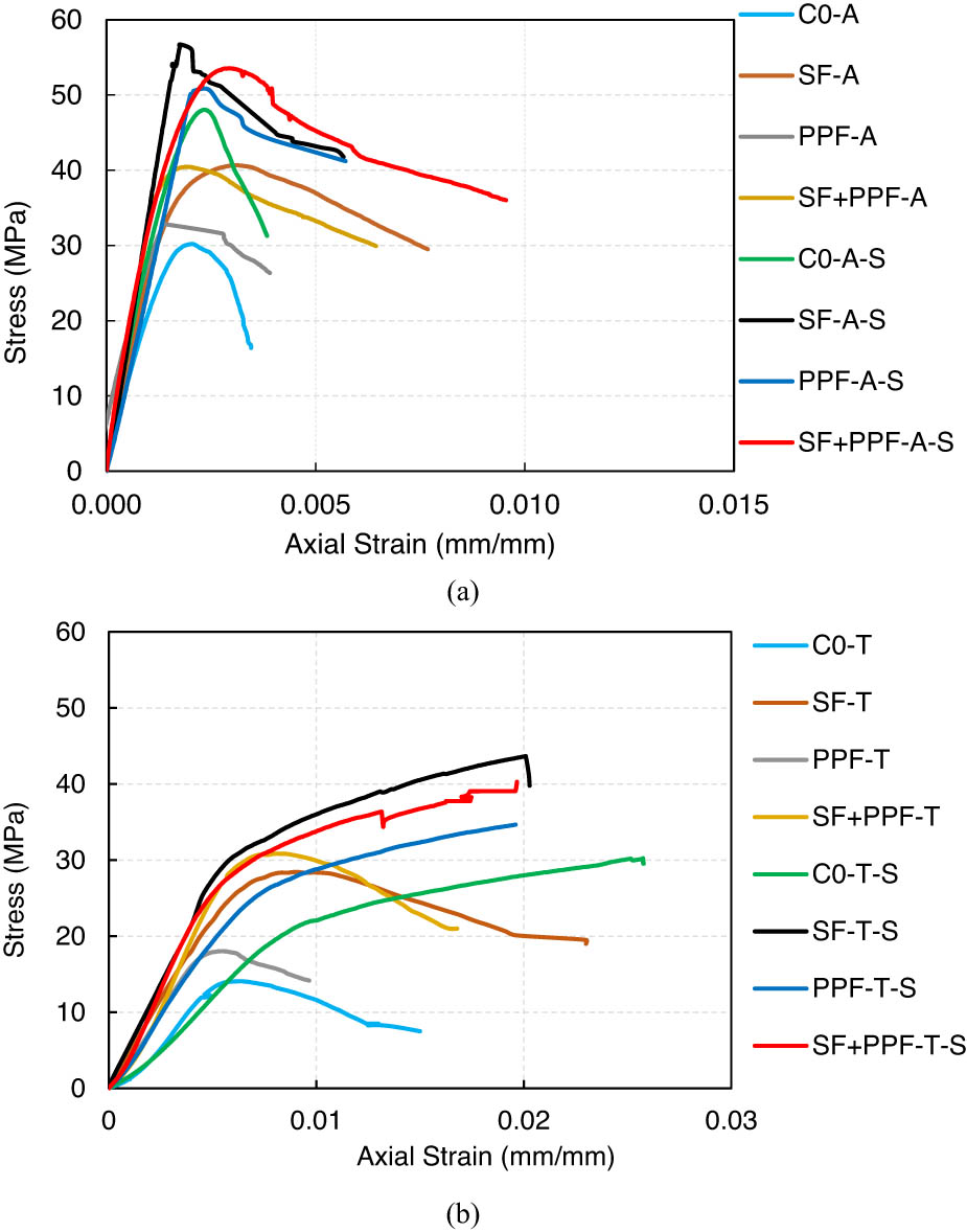
Figure 7
Stress–axial strain curves for all concrete cylinders at (a) 26°C and (b) 600°C.
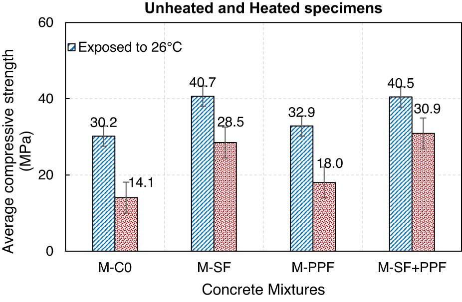
Figure 8
Effect of fiber types on compressive strength of concrete mixtures.
Table 5
Summary of experimental test results.
| Specimens | Compressive strength (MPa) | f cc/f c* | Relative difference (%) ** | Initial stiffness (N/mm) | Relative difference (%)* |
|---|---|---|---|---|---|
| C0-A | 30.2 | — | — | 20133.3 | — |
| C0-T | 14.1 | — | −53.3 | 2169.2 | −89.2 |
| C0-A-S | 48.1 | 1.59 | +59.1 | 34945.5 | +73.6 |
| C0-T-S | 30.2 | 2.14 | +0.1 | 2419.3 | −88.0 |
| SF-A | 40.7 | — | — | 26688.5 | — |
| SF-T | 28.5 | — | −30.0 | 4560.0 | −82.9 |
| SF-A-S | 56.7 | 1.39 | +39.3 | 32400.0 | +21.4 |
| SF-T-S | 43.6 | 1.53 | +7.2 | 8729.1 | −67.3 |
| PPF-A | 32.9 | — | — | 43866.7 | — |
| PPF-T | 18.0 | — | −45.3 | 3600.0 | −85.0 |
| PPF-A-S | 50.7 | 1.54 | +54.1 | 33800.0 | +41.3 |
| PPF-T-S | 35.3 | 1.96 | +7.2 | 4029.4 | −83.2 |
| SF + PPF-A | 40.5 | — | — | 27000.0 | — |
| SF + PPF-T | 30.9 | — | −23.7 | 4414.3 | −83.7 |
| SF + PPF-A-S | 53.5 | 1.32 | +32.1 | 35666.7 | +32.1 |
| SF + PPF-T-S | 40.1 | 1.30 | −1.1 | 5342.0 | −80.2 |
*f cc/f c is the confinement effectiveness ratio.
**The control specimen in each mixture is used as a reference specimen. A “+” sign refers to an increase, whereas a “−” sign refers to a reduction.
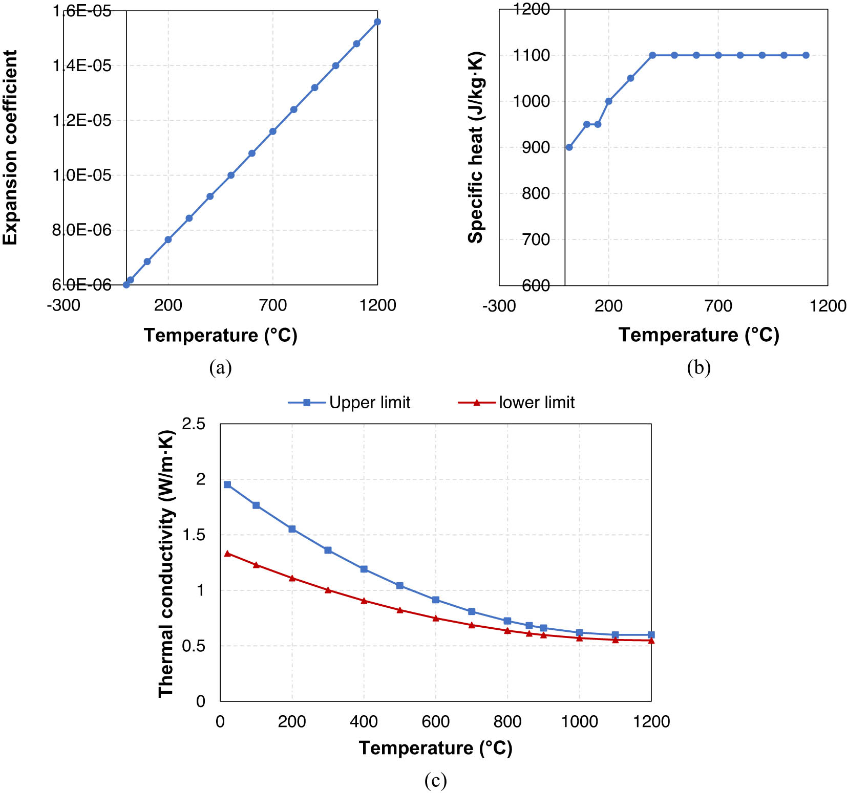
Figure 9
The concrete’s thermal properties at various temperatures: (a) expansion coefficient, (b) specific heat, and (c) thermal conductivity.
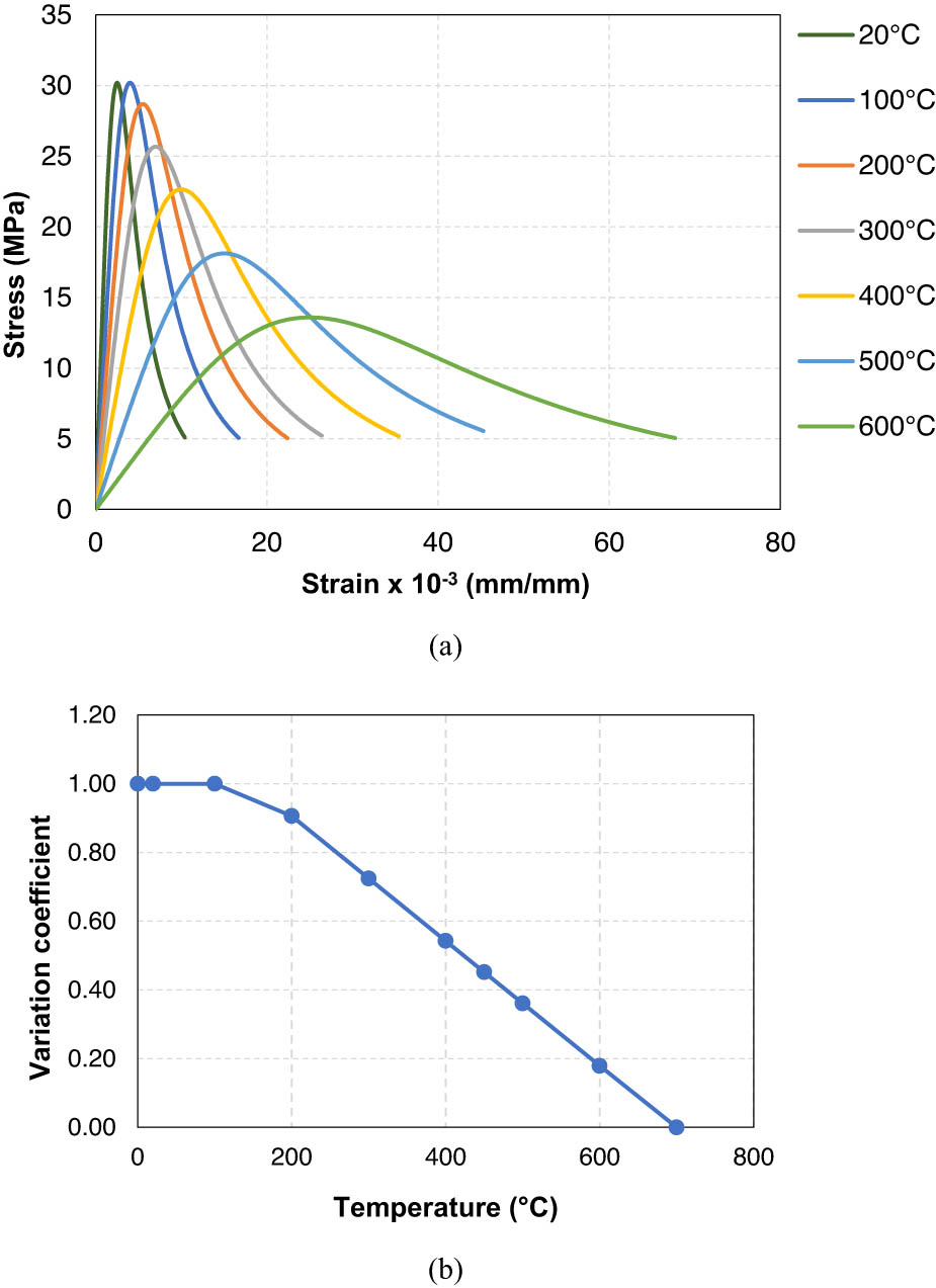
Figure 10
The concrete’s mechanical properties at various temperatures: (a) stress–strain curves for unconfined deep beam (C0-A) and (b) reduction coefficient for modulus of elasticity.
Table 6
Parameter values of concrete damaged plasticity model in this study.
| Parameters | Dilation angle (°) | Potential eccentricity | Biaxial to uniaxial compressive strengths | Compressive meridian | Viscosity parameter |
|---|---|---|---|---|---|
| Unconfined concrete | 30 | 0.1 | 1.16 | 0.7 | 0 |
| Confined concrete | 15 | 0.1 | 1.16 | 0.7 | 0 |
Table 7
Parameter values of CFRP material characteristics in this study.
| Parameters | Value | ||
|---|---|---|---|
| Elastic properties | Poisson’s ratio | N | 0.3 |
| Elastic modulus | E 1 (MPa) | 220 | |
| E 2 (MPa) | 10 | ||
| Modulus of rigidity | G 12 = G 13 (MPa) | 5 | |
| CFRP strength | Tensile strength | f t1 (MPa) | 3,000 |
| f t2 (MPa) | 12 | ||
| Compressive strength | f c1 = f c2 (MPa) | 12 | |
| Shear strength | V f1 = V f2 (MPa) | 12 | |
| Damage evolution | Tensile fracture energy | G t1 (mJ/mm2) | 95 |
| G t2 (mJ/mm2) | 1.2 | ||
| Compressive fracture energy | G c1 (mJ/mm2) | 95 | |
| G c2 (mJ/mm2) | 1.2 | ||
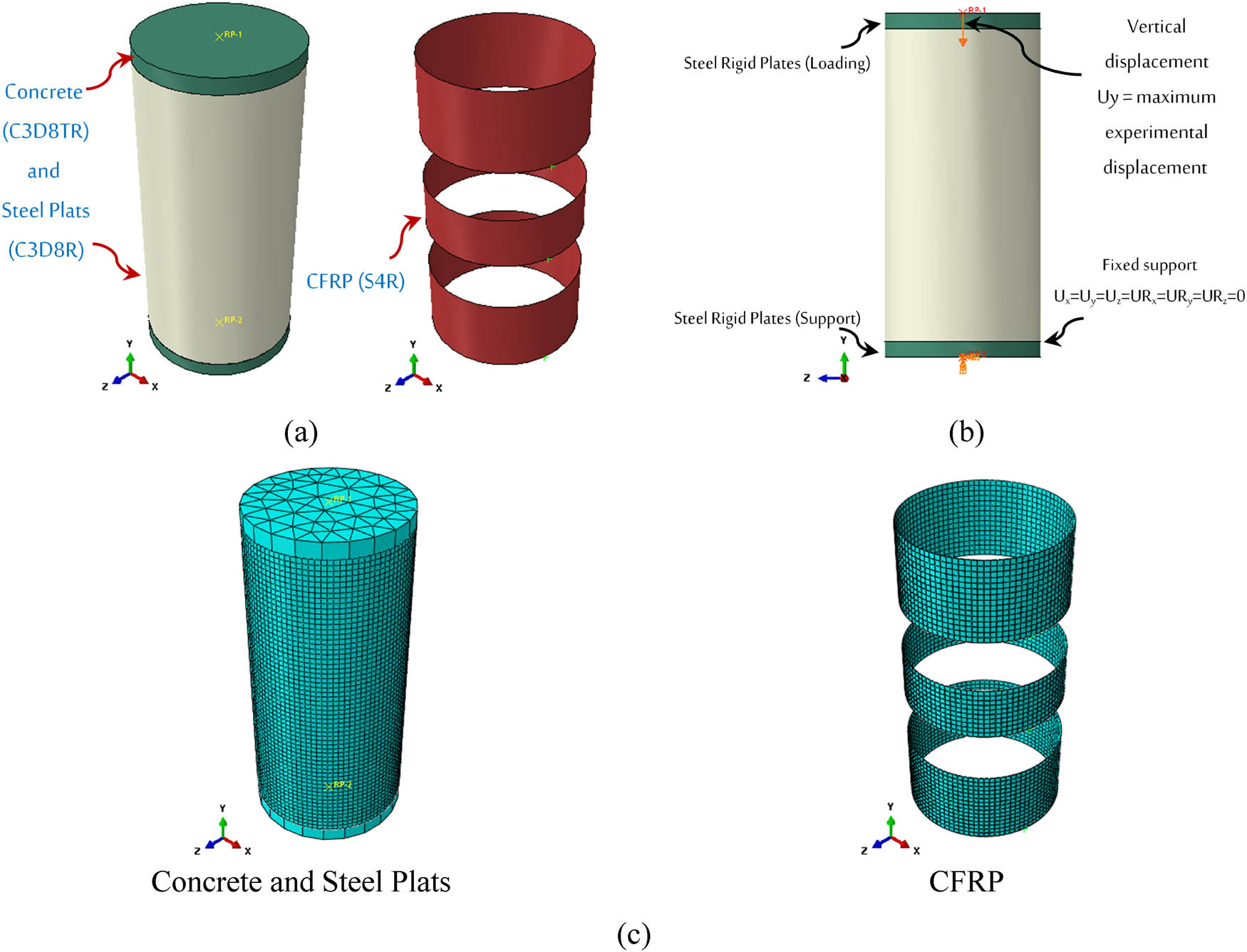
Figure 11
FE simulation steps: (a) element types, (b) load and support, and (c) meshing size.
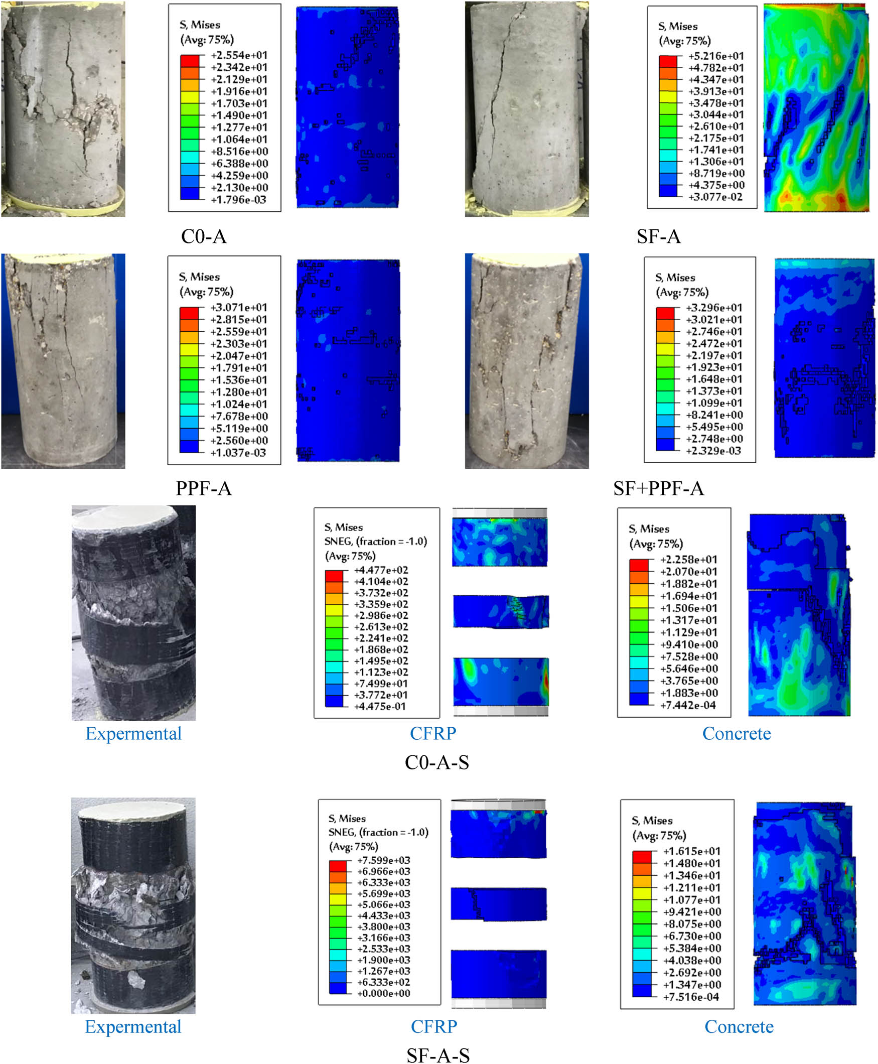
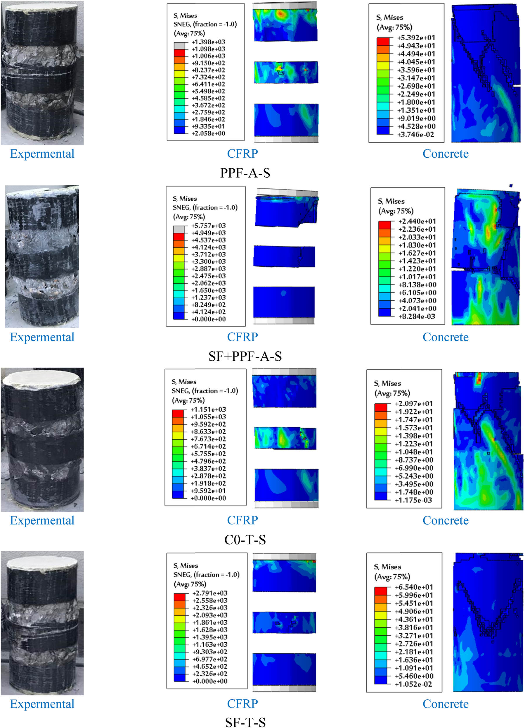
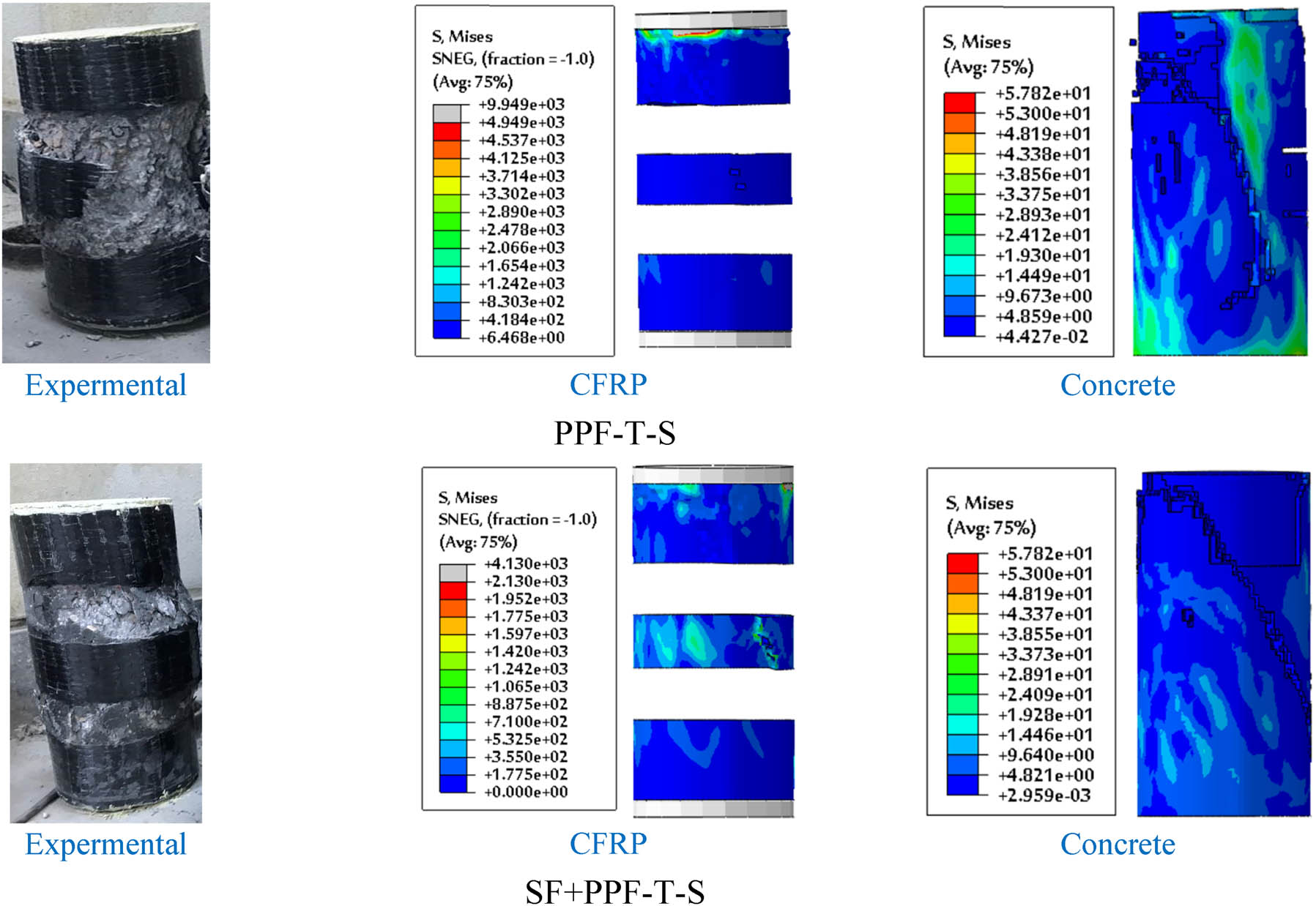
Figure 12
Failure mode of FE specimens.
Table 8
FE and experimental test results.
| Specimens ID | Compressive strength (MPa) | Experimental/FE | |
|---|---|---|---|
| Experimental | FE | ||
| C0-A | 30.2 | 31.3 | 1.04 |
| C0-T | 14.1 | 15.2 | 1.08 |
| C0-A-S | 48.1 | 51.7 | 1.07 |
| C0-T-S | 30.2 | 32.1 | 1.06 |
| SF-A | 40.7 | 43.1 | 1.06 |
| SF-T | 28.5 | 30.5 | 1.07 |
| SF-A-S | 56.7 | 59.4 | 1.05 |
| SF-T-S | 43.6 | 46.9 | 1.08 |
| PPF-A | 32.9 | 34.7 | 1.05 |
| PPF-T | 18.0 | 19.8 | 1.10 |
| PPF-A-S | 50.7 | 54.3 | 1.07 |
| PPF-T-S | 35.3 | 38.4 | 1.09 |
| SF + PPF-A | 40.5 | 43.8 | 1.08 |
| SF + PPF-T | 30.9 | 34.1 | 1.10 |
| SF + PPF-A-S | 53.5 | 58.4 | 1.09 |
| SF + PPF-T-S | 40.1 | 44.2 | 1.10 |