
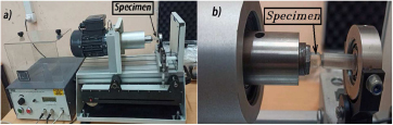
Fig. 1.
Rotary bending fatigue machine SM1090
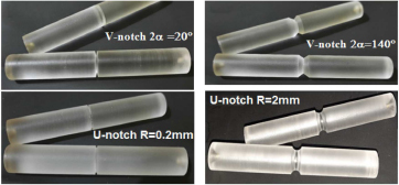
Fig. 2.
Manufacture of notched specimens
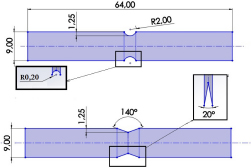
Fig. 3.
Recommended specimen sizes
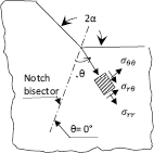
Fig. 4.
Stress components located at the point of the tip of the V-notch, in a polar coordinate system
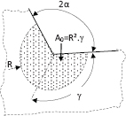
Fig. 5.
Circular zone nears tip of V-notch [8], 2γ = 2π − 2α
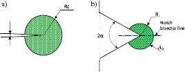
Fig. 6.
Control volume A0 for (a) sharp crack, (b) V-notch
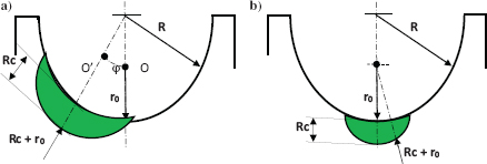
Fig. 7.
Control volume for U-notch: (a) mixed-mode I/II, (b) open mode I
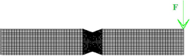
Fig. 8.
Bi-dimensional finite elements model
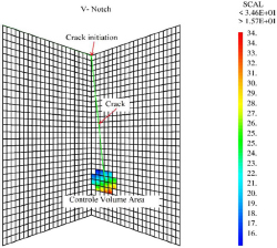
Fig. 9.
Crack propagation emanating from the V notch and the location of the control volume
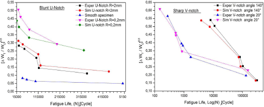
Fig. 10.
Comparisons of experimental and simulation values of ASED for sharp V notch and blunt U notch via fatigue life
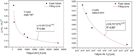
Fig. 11.
Approximation of ASED via fatigue life
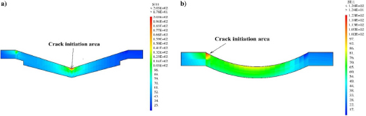
Fig. 12.
Location of the zone of maximum principal stress (crack initiation zone) for (a) U notch R = 2 mm and (b) V notch 2α = 140°
Table 1.
Mechanical properties of PMMA
| Tensile strength (MPa) | Flexural strength (MPa) | Modulus of elasticity (MPa) | Density (kg/m3) | Elongation (%) | Poisson’s rate | Fracture Toughness (MPa.√m) |
|---|---|---|---|---|---|---|
| 70.5 | 110 | 3000 | 1190 | 6 | 0.3 | 1.863 |
Table 2.
Local energy modeling near notch
| Experimental | ||
|---|---|---|
| Notch type | Correlation coefficients | Experimental: Local energy near notch |
| U-notch radius 0.2 mm | R2 = 0.9881 | WU0.2 = 6,1122.(2N)-0.248 |
| V-notch angle 20° | R2 = 0.9591 | WV20 = 0,9019.(2N)-0.13 |
| V-notch angle 140° | R2 = 0.9656 | WU140 = 10,939.(2N )-0.325 |
| U-notch radius 2 mm | R2 = 0.8875 | WU2 = 14,731.(2N )-0.381 |
| Simulation | ||
| Notch type | Correlations coefficients | Simulation: Local energy near notch |
| U-notch radius 0.2 mm | R2 = 0.967 | WU0.2 = 25.707.(2N )-0.354 |
| V-notch angle 20° | R2 = 0.857 | WV20 = 1.944. (2N )-0.2093 |
| V-notch angle 140° | R2 = 0.890 | WU140 = 15.357.(2N )-0.392 |
| U-notch radius 2 mm | R2 = 0.8305 | WU2 = 12.483.(2N )-0.37 |
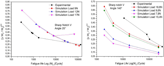
Fig. 13.
Effect of loading on averaged energy density for V-notch via fatigue life (logarithmic values)
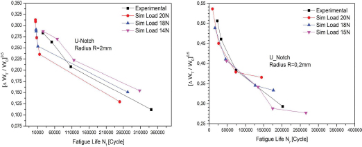
Fig. 14.
Effect of loading on averaged energy density blunt U notch
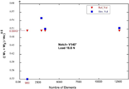
Fig. 15.
Effect of the number of mesh elements
Table 3.
Correlations of experimental and numerical results
| Experimental test | |||||||
|---|---|---|---|---|---|---|---|
| Notch type | Number of test repetitions | Min. number of cycles | Max. number of cycles | Standard deviation of cycles | Minimum energy | Maximum energy | Standard deviation of energy |
| U-notch radius 0.2 mm | 4 | 22640 | 201,865 | 82391.597 | 0.293 | 0.507 | 0.094 |
| V-notch angle 20° | 4 | 521,218 | 151,883 | 75622.87 | 0.229 | 0.461 | 0.107 |
| V-notch angle 140° | 4 | 11032 | 311,170 | 129198.70 | 0.166 | 0.504 | 0.143 |
| U-notch radius 2 mm | 5 | 25,239 | 341,478 | 125086.76 | 0.112 | 0.283 | 0.074 |
| Simulation tests | |||||||
| Notch type | Number of test repetitions | Min number of cycles | Max number of cycles | Standard deviation of cycles | Minimum of energy | Maximum of energy | Standard deviation of energy |
| U-notch radius 0.2 mm | 4 | 15254 | 326,645 | 146,519.222 | 0.255 | 0.438 | 0.080 |
| V-notch angle 20° | 5 | 150.43 | 151,883 | 67,693.93 | 0.229 | 0.609 | 0.141 |
| V-notch angle 140° | 4 | 3890.97 | 85,337 | 42857.97 | 0.253 | 0.538 | 0.139 |
| U-notch radius 2 mm | 5 | 22938.2 | 442,920 | 169,677.83 | 0.124 | 0.313 | 0.081 |