
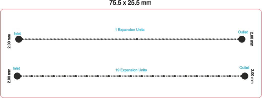
Fig.1:
Schematic diagram of chip A.
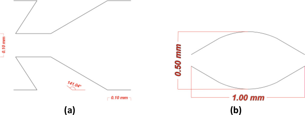
Fig.2:
Detailed schematic diagram of the jagged teeth and expansion unit. (a) Jagged teeth dimensions, (b) The expansion unit dimensions.

Fig.3:
Schematic diagram of chip B.
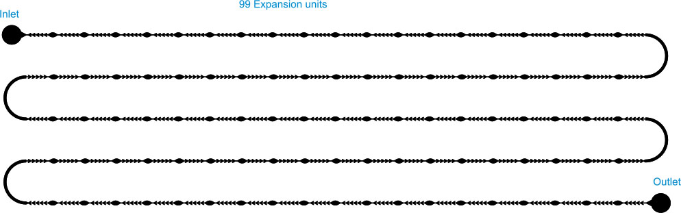
Fig.4:
Schematic diagram of the third denudation chip
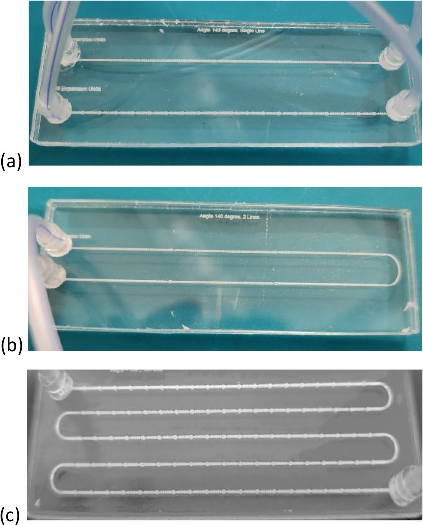
Fig.5:
The Fabricated Chips with the connected tubes. (a) Chip A. (b) Chip B. (c) Chip C.
Table 1:
The maturation media concentrations [62].
| Component | Final Concentration |
|---|---|
| TCM 199 | 9 ml |
| Fetal Bovine Serum | 1 ml |
| Amphotericin B | 1 ml |
| FSH | 10 µl |
| Sodium Pyruvate | 20 µl |
| Gentamycin | 10 µl |
| Estradiol 17β | 10 µl |
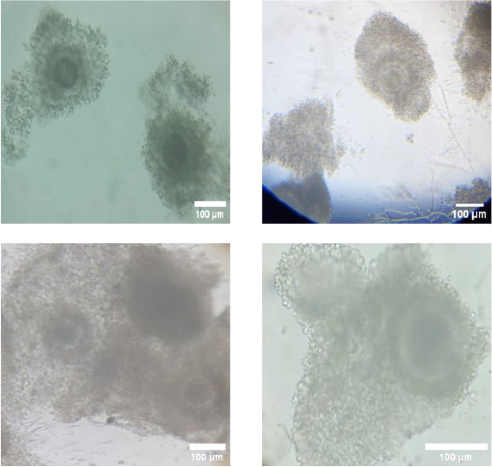
Fig.6:
Different shots of the Mature oocytes with cumulus cells under the microscope.
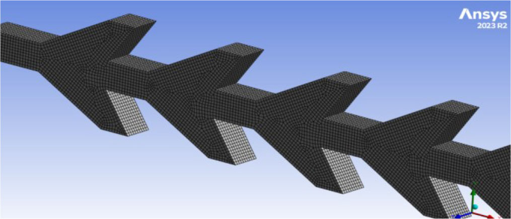
Fig.7:
Meshing analysis in Ansys.
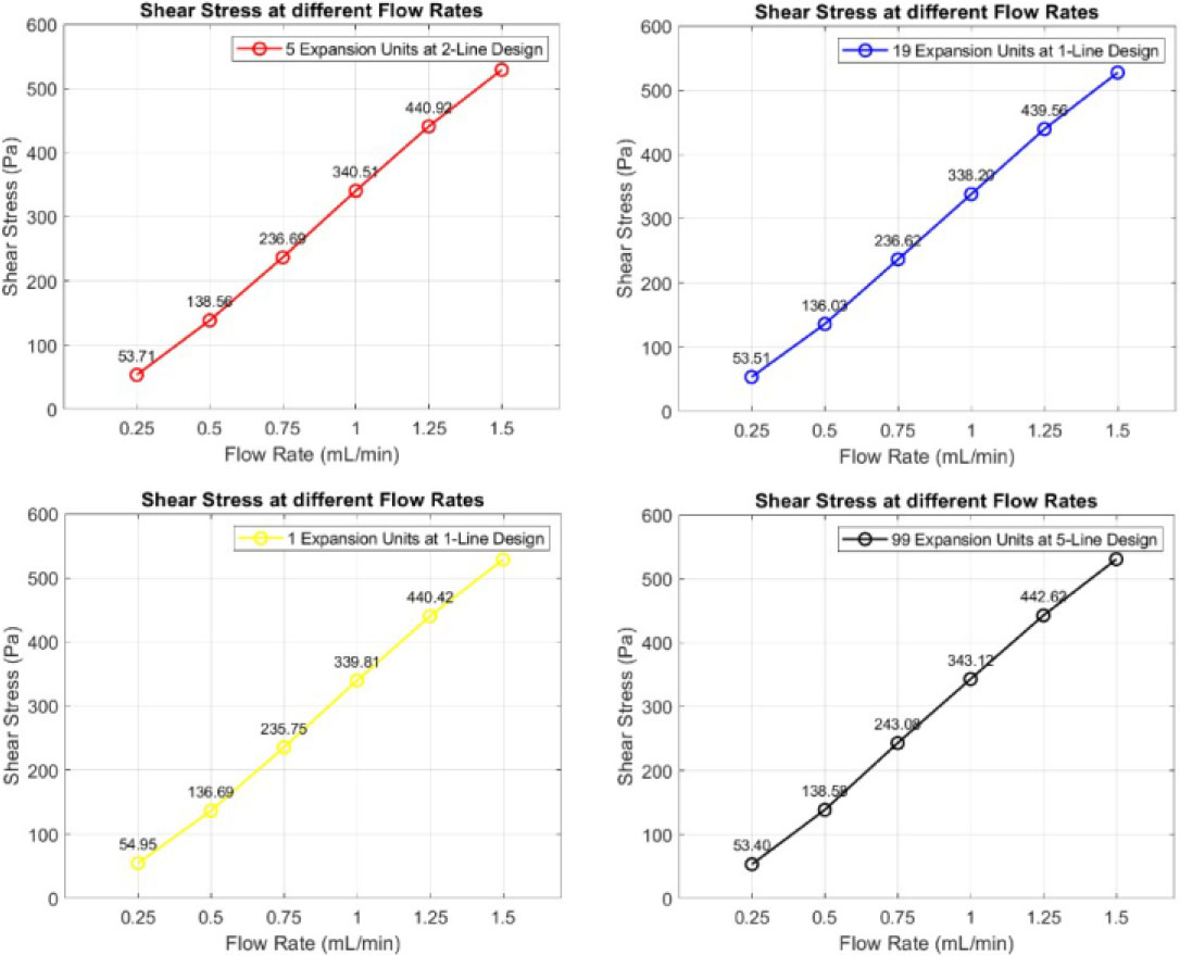
Fig.8:
Shear stress at each design’s first pair of teeth at different flow rates.
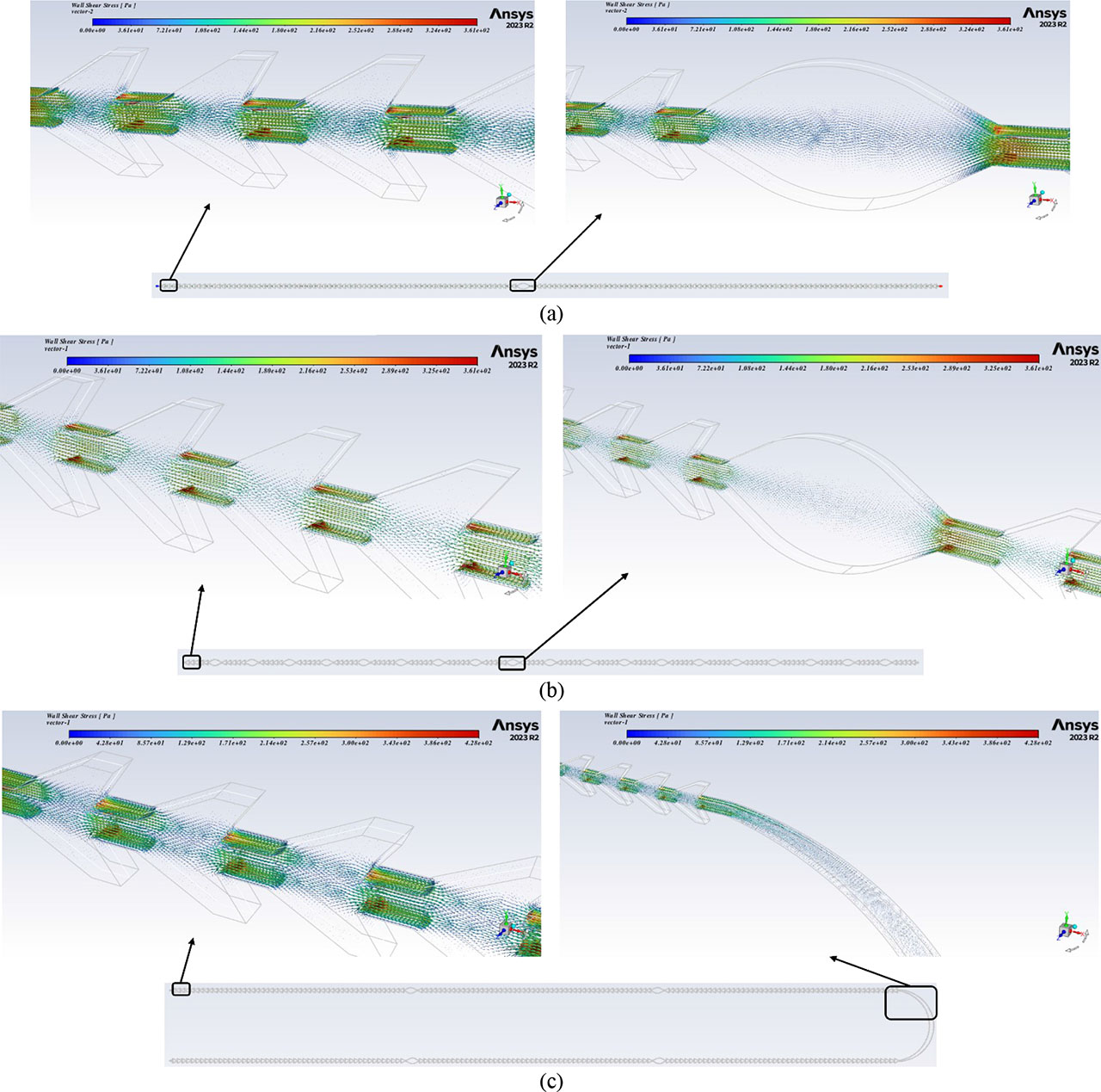
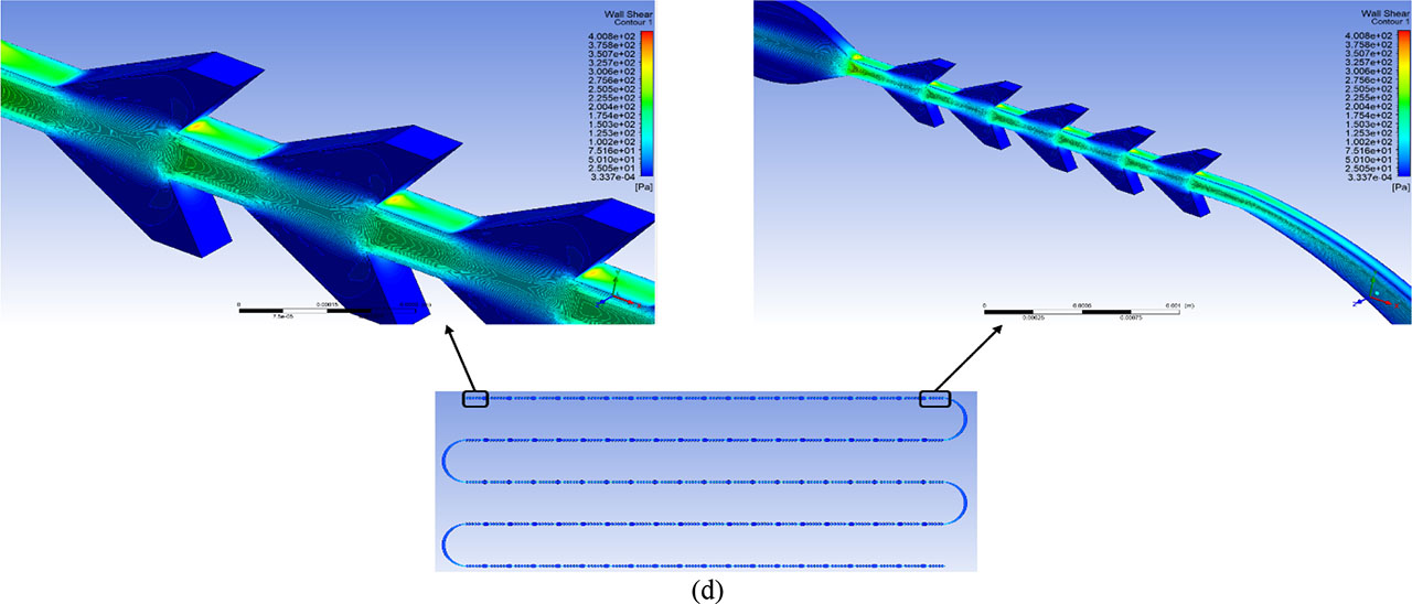
Fig.9:
The simulation results of the chips on Ansys. (a) The first channel of chip A is “1 expansion unit at 1 line design”. (b) The second channel of chip A is “19 expansion units at 1 line design”. (c) Chip B is “5 expansion units at 2-line design”. (d) Chip C is “99 expansion units at 5-line design”.
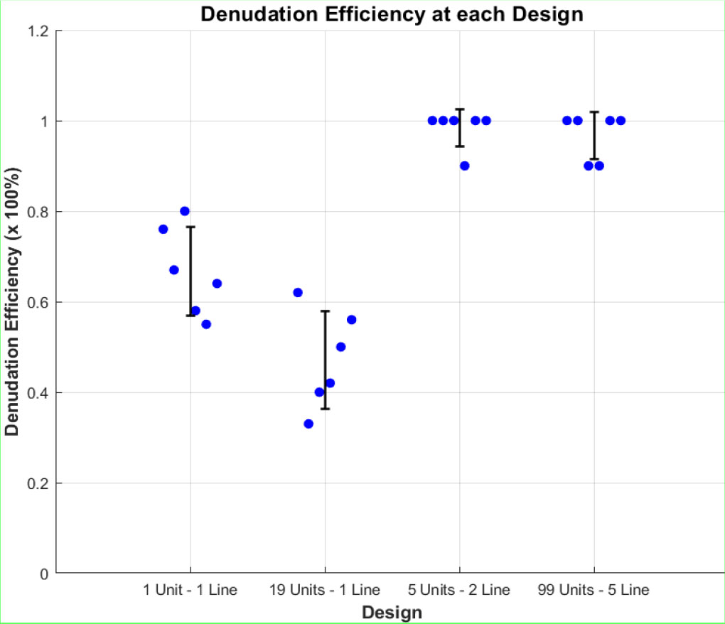
Fig.10:
Denudation efficiency at the three chips. Where the first two channels belong to chip A, the third channel belongs to chip B, and the fourth channel belongs to chip C.
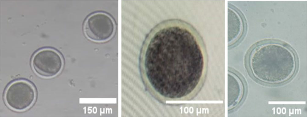
Fig.11:
Shots of the complete denudated oocytes.
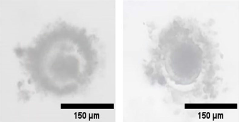
Fig.12:
Shots of the incomplete denudated oocytes.
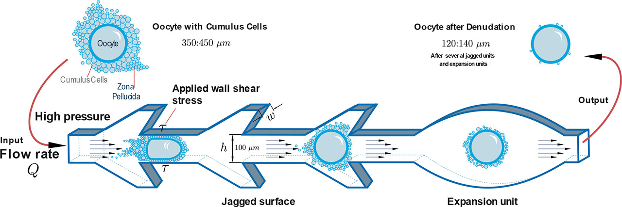
Fig.13:
The mechanical concept of the microfluidic chips.