
Fig.1
Fig.2
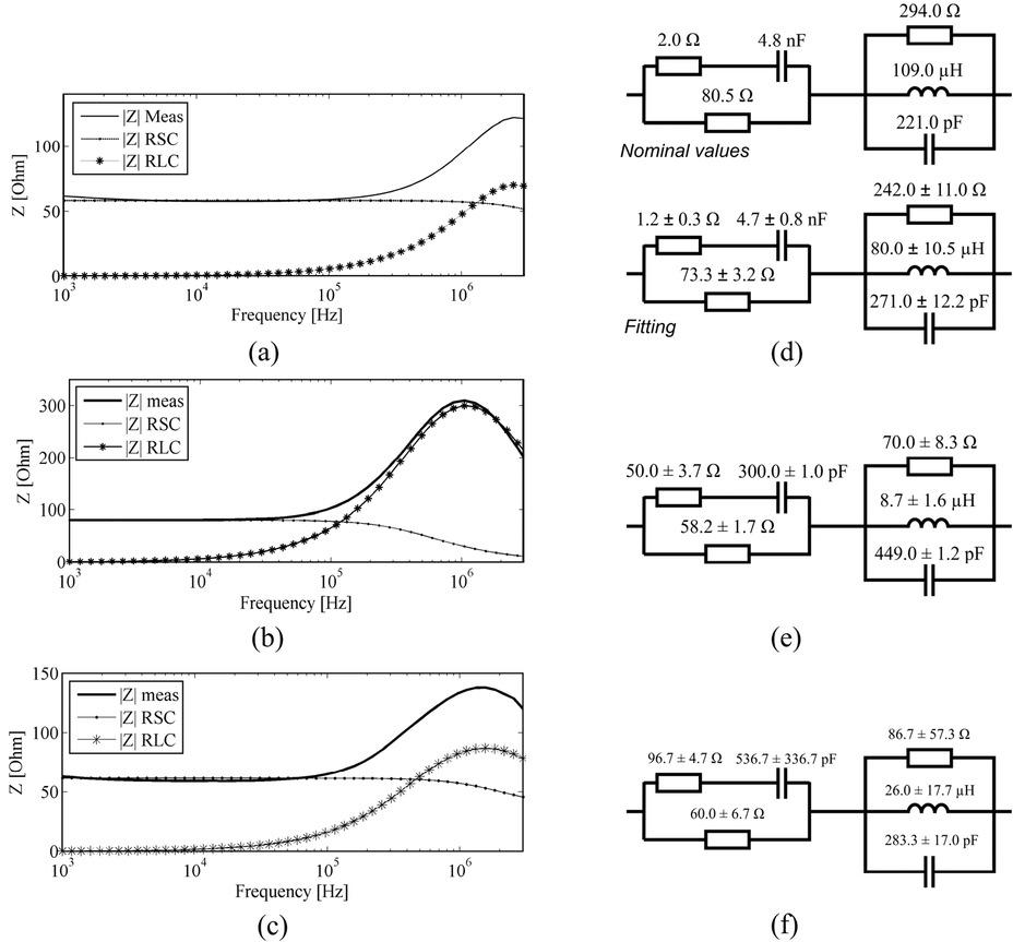
Measured and fitted values for circuits 1 to 4, where NA means that the resonance frequency was not measured_
| Circuit 1 | Circuit 2 | Circuit 3 | Circuit 4 | |||||
|---|---|---|---|---|---|---|---|---|
| C1[nF] | 1.00 | 1.01 | 1.00 | 1.15 | 4.70 | 4.81 | 0.82 | 0.87 |
| R2 [Ω] | 56.8 | 55.8 | 50.5 | 50.4 | 73.3 | 80.5 | 65.2 | 67.5 |
| R3 [Ω] | 1.2 | 1.9 | 1.2 | 1.5 | 1.2 | 2.0 | 1.2 | 1.3 |
| R1 [Ω] | 1.1 | 1.5 | 1.1 | 0.7 | 242.0 | 294.0 | 61.9 | 61.0 |
| L [μF] | 100.0 | 101.0 | 2.7 | 2.5 | 80.0 | 109.0 | 15.0 | 17.3 |
| C2 [pF] | 0.0 | 0.001 | 15.0 | 18.0 | 271.0 | 221.0 | 271.0 | 350.0 |
| R∞ [Ω] | 1.2 | 1.3 | 1.2 | 1.1 | 1.2 | 2.0 | 1.2 | 1.3 |
| fC[Hz] | 2.74 | 2.25 | 3.08 | 2.58 | 0.45 | 0.40 | 2.87 | 2.66 |
| fR[Hz] | NA | 9.60 | 25.00 | 22.80 | 0.34 | 1.03 | 2.50 | 2.02 |
| RMSRE | 0.80 | 0.15 | 0.15 | 0.18 | ||||