
I. Introduction
Antenna arrays are an important element in the operation of contemporary communication systems such as wireless networks, satellite communications, radar, and mobile base stations [1]. It offers desirable capabilities because it can transmit and receive electromagnetic signals in an intentional and controllable fashion [2]. As a result of the multiple antenna elements, it can also improve signal quality, increase coverage area, and better utilize the available frequency spectrum [3]. The key antenna arrays are the ability to form steerable beams and achieve higher directivity, directing and concentrating radiated energy toward desired directions, while reducing interference from undesired sources [4]. The performance and efficiency of an entire communication system ultimately rely on how well the antenna array is designed and optimized [5]. In order for the communication to be reliable over long distances, the antenna arrays must meet a number of performance requirements. A narrow main beam is needed to create high directivity and efficiently direct the radiated power [6]. At the same time, the array elements must also ensure that low SLL is maintained to avoid disturbing other systems operating in similar frequency bands [7]. Another essential design requirement is to maximize the steering capabilities of the antenna by creating the nulls in the desired directions in which interference, or unwanted signals, are present. The requirements are often opposing [8].
For example, decreasing the main beam may lead to an increase in the side lobe levels (SLLs), and minimizing side lobes may lead to an increase in the beam and decrease directivity [9]. So an optimal tradeoff between beam width, SLL, and null placement is still no easy or simple task [10]. Wireless communications have been increasing quickly in recent years, creating increased signal interference among different wireless radios [11]. As such, many current antenna arrays must support both adaptive null steering and dynamic suppression of unwanted wireless signals to provide reliable wireless communications [12]. The ability to effectively mitigate interference relies significantly on the accurate control of the directivity of an antenna’s radiation pattern [13]. In recent literature, many techniques have demonstrated the ability to manipulate the radiation pattern by either varying the amplitude, phase, or both of the individual elements of the antenna array [14]. Other research has focused on creating nonuniform or aperiodic antenna array configurations to facilitate interference suppression and enhance the flexibility of the radiation pattern [15]. While these methods can provide some flexibility, they may not be sufficient for modern systems that require the placement of several nulls at asymmetrical or irregular angles around the main beam [16]. In such cases, phase-only control is often preferred because it allows a direct manipulation of the beam direction and null locations without altering the physical geometry or increasing system complexity [17]. Existing techniques often face limitations in solving these highly nonlinear, multidimensional problems. To address these difficulties, researchers have increasingly turned to nature-inspired optimization algorithms that simulate biological or natural processes such as genetic evolution, swarm intelligence, or ecosystem adaptation [18]. Although several studies have applied nature-inspired algorithms for antenna array pattern synthesis, many existing methods still face challenges [19]. Some algorithms converge prematurely, resulting in suboptimal array configurations. Others may require high computational time to balance the tradeoff between narrow beam formation and side lobe suppression [20]. To overcome these challenges, a novel optimization strategy is proposed. The major contributions of this paper are;
To develop an adaptive array pattern nulling framework utilizing a novel MLIWO, aiming to enhance null depth (ND), suppress sidelobes, and improve adaptive robustness, thereby providing an effective approach for interference mitigation in advanced defense and communication environments.
To evaluate system performance using critical parameters, including ND to measure interference rejection, SLL to control signal leakage, main-lobe integrity, and BW to maintain signal accuracy, SINR and Array gain to assess output effectiveness, as well as convergence rate and computational efficiency to verify real-time operability, alongside robustness indicators to confirm adaptability under varying environmental conditions.
To implement and validate the proposed methodology in MATLAB, demonstrating that the MLIWO approach effectively achieves deeper nulls, reduced sidelobe levels and consistent adaptive performance.
The remaining section of this paper is organized as follows; section 2 describes the literature survey based on array pattern nulling. Section 3 discusses the proposed methodology for interference cancellation. In section 4, the results and discussion are described for evaluating the performance and the conclusion part with future scope is explained in section 5.
II. Literature Survey
Several researchers have explored array pattern nulling techniques to effectively suppress interference and improve beamforming performance and it is explained in the below:
Mou et al. [21] established a pattern synthesis method for linear antenna arrays (LAA) using the sand cat swarm optimization (SCSO) algorithm to achieve high gain and low SLL. The approach was optimized for key parameters phase, amplitude, position and rotation to efficiently control the radiation characteristics of the array. The full-wave method of moments (MoM) was employed to account for mutual coupling between elements, ensuring design accuracy. The results showed that, compared to genetic algorithm (GA), grey wolf optimization (GWO) and particle swarm optimization (PSO), the suggested SCSO algorithm acquires faster convergence while maintaining high gain and potential as a robust optimization.
Liu et al. [22] introduced the chaos triangular pelican optimization algorithm (CTPOA), which enhanced the original pelican optimization algorithm (POA) by incorporating logistic chaotic mapping for initialization and triangular walk strategy to improve search efficiency. The algorithm was implemented on linear array antennas (LAA) pattern synthesis for the first time and in the simulation results of four antennas its optimization performance was demonstrated to be exceptional. Overall, CTPOA was shown to be a reliable and effective optimization technique in the arena of antenna arrays design.
Li et al. [23] introduced the Dandelion optimization (DO) algorithm and utilized it in the design of linear antenna arrays for the first time. The optimization of the array was targeted toward ultra-low SLL and deep nulls to have enhanced interference cancellation. The DO optimization method is inspired by the behavior of dandelions distributing themselves to the wind using ascent, descent and landing stages to effectively search for optimal solutions. The outcomes proved that the suggested DO approach obtains superior convergence and optimization performance as compared to FPA, GWO, CCPA, SMO, GOA, and crow search optimization (CSO) algorithms for linear array design. The DO algorithm acquired deeper nulls and lower sidelobes for the desired level of SLL which did not increase main lobe width. The DO method demonstrates its effectiveness and robustness for more advanced antenna array optimization.
Raghuvanshi et al. [24] discussed the modified arithmetic optimization algorithm (MAOA), a new optimization technique designed for applications within electromagnetic domains. Its contributions to the algorithms performance were achieved through improved initialization, guided search mechanisms and an added learning phase which incorporated an improved balance between global exploration and local exploitation. The suggested technique was subsequently utilized to optimize the element spacing and current amplitudes of linear antenna arrays (LAA) to minimize peak close-in and overall SLLs (PSLL, CSLL, and SLL) while controlling beam width and null placement. The findings indicated superior radiation patterns than conventional uniform linear arrays (ULAs) and other related optimizations.
Cheng et al. [25] presented an approach for overcoming main lobe interferences utilizing a criterion of maximum output SINR. They implemented the adaptive particle swarm optimization (APSO) algorithm to optimize the interference parameters iteratively improving convergence speed and optimization performance. The APSO-based technique has steadily enhanced both robustness and reliability in radar signal processing. The results indicated that the proposed method could achieve improved inference mitigation. The suggested approach was validated as effective by combining a global optimization with adaptive algorithms in radar systems.
Manai et al. [26] introduced an advanced blind adaptive 3D beam steering method to reduce interference and improve the efficiency of massive systems. The technique integrated an optimized direction of arrival (DoA) estimation with adaptive signal processing to enhance the signal-to-interference-plus-noise ratio. A modified RD-MUSIC estimator is employed to simply the 2D-DoA estimation into 1D search, which lowered computational complexity while preserving the accuracy. The approach was acquired better SINR compared to conventional algorithms. Overall, the suggested model was highly suitable for dynamic and interference-prone wireless environments. Table 1 depicts the comparative analysis of existing works.
Table 1:
Comparative analysis of existing works
| References | Techniques | Advantages | Disadvantages |
|---|---|---|---|
| Mou et al. [21] | SCSO algorithm | High gain, fast convergence | Complex parameter tuning |
| Liu et al. [22] | CTPOA | High efficiency | Complex structure |
| Li et al. [23] | DO algorithm | Fast convergence | High complexity, parameter sensitivity |
| Raghuvanshi et al. [24] | MAOA | Low SLL, balanced optimization | Complex design, slower execution |
| Cheng et al. [25] | APSO | Fast convergence, high robustness | Complex tuning, high computation |
| Manai et al. [26] | modified RD-MUSIC | Reduced interference, high SINR, low complexity | High processing demand, sensitive to DoA |
[i] APSO, adaptive particle swarm optimization; CTPOA, chaos triangular pelican optimization algorithm; DO, Dandelion optimization; DoA, direction of arrival; MAOA, modified arithmetic optimization algorithm; MUSIC, multiple signal classification; SCSO, Sand Cat Swarm Optimization; SINR, signal to interference plus noise ratio; SLL, sidelobe level.
Existing optimization methods in antenna array design face several limitations that affect their overall performance and adaptability. One major challenge lies in maintaining an effective balance between the sidelobe suppression and main-lobe integrity while optimizing multiple array parameters simultaneously. Many traditional algorithms are often affected by premature convergence, leading to subpar radiation patterns and decreased interference rejection capabilities. The computational burden grows substantially high, especially for large-scale or complex antenna systems. Some of the existing approaches are also not agreeable to adapt to dynamic interference environments, which limit the framework’s applicability to real-time scenarios. The adaptive array pattern nulling framework is opponent to mitigate these deficits. The framework used an innovative MLIWO algorithm to improve optimization accuracy and stability.
III. Proposed Methodology
Modern antenna array systems play a pivotal part in military, radar, and secure communication applications for retaining high directivity and reliable signal reception in the presence of interference and noise. If in practice these systems are faced with a considerable number of challenges, such as multiple jammers, a dynamic inference environment, moving sources, and a changing noise environment. Traditional beam forming and null steering algorithms may struggle to keep the integrity of the main lobe while establishing deep nulls for the interference directions, and is even more difficult in rapidly changing environments or if the signal environment is poorly known. To address the challenges, this study analyzed an adaptive array pattern nulling methodology which is based on MLIWO. The methodology starts with a signal capture and digitization stage where the antenna array facilitates the captured superposition of desired signal, interference and noise and converts the analog inputs to digital form for accuracy in processing. The next stage is a signal environment estimation stage that evaluates the interference direction and spatial characteristics using high-resolution techniques such as MUSIC and ESPRIT that provides critical situational awareness to lead the adaptive optimization process. The proposed method is based upon the adaptive weight calculations with MLIWO where the arrays weight vector is continuously optimized to suppress the interference energy yet maintain the main lobe. The use of Laplace distributed mutation allows for an enhanced exploration of the solution space to avoid the limitations of traditional evolutionary algorithms that tend to become stuck in local optima. In the null forming and signal combining process optimized weights are applied to the array elements to create accurate nulls in the direction of the interference producing a beam formed output that is assessed in terms of ND, SLL, and main lobe preservation. The resulting output is a clean signal output of interference suppressed signals that is suitable for target detection, communication, or radar tracking functionality. To achieve robust performance in dynamic environments, an adaptation loop can continuously monitor environmental changes, including moving jammers or other variants of noise, and trigger re-optimization as necessary. Real time adaptability results in continued interference suppression and fidelity of the signal while addressing the key limitations of legacy beam forming approaches.
Figure 1 depicts the Block diagram for the proposed methodology.
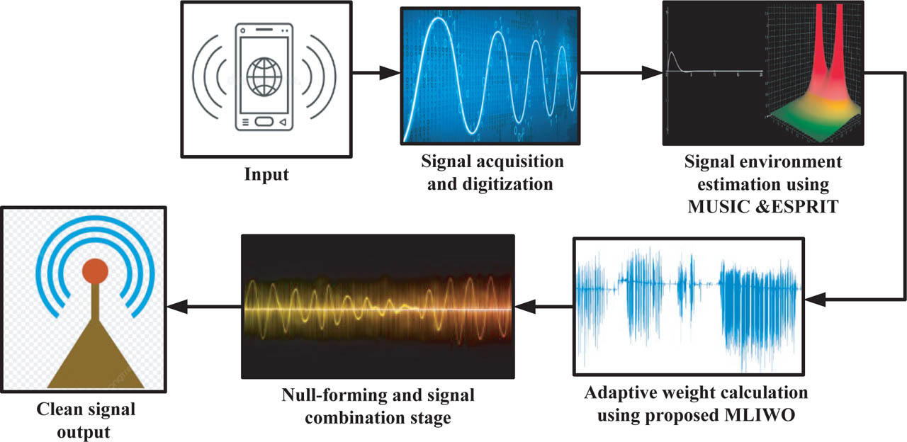
Figure 1:
Block diagram for the proposed methodology. MUSIC, multiple signal classification; ESPRIT, estimation of signal parameters via rotational invariance techniques.
a. Signal acquisition and digitization
The process begins with the acquisition and digitization of signals. The antenna arrays will collect the desired signal plus interfering sources and background noise. The incoming analog waveform is converted into digital form to process the data computationally accurately. The digitization step is needed for the effective application of adaptive algorithms. By transforming signals into discrete data samples, the system provides for accurate data, which is crucial in the analysis and beam forming. This Stage provides the foundation for the signal quality optimization and interfering signal suppression in later processing stages.
a.i. Linear array antenna configuration
The recommended design employed a ULA made up of 2N identical radiating elements that were symmetrically spaced down the x-axis [27]. The configuration guarantees identical spacing and symmetric position of the radiating elements with respect to the center, as shown in Figure 2. The array factor (AF), which indicates the radiation characteristics of the array, can be expressed as:
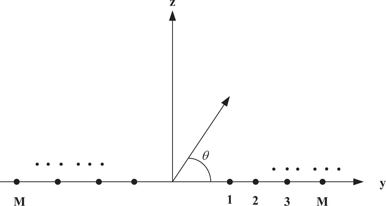
Figure 2:
Geometry of the linear 2N-element symmetrically placed antenna array.
From the above equation, indicates the wave number, θ represents the azimuth angle while Im, ψm, and yn denotes the excitation magnitude phase offset and spatial location of the mth antenna element. This configuration enables controlled beam formation and improved radiation symmetry. Figure 2 depicts the Geometry of the linear 2N-element symmetrically placed antenna array.
a.ii. Digitization process
The analog signal yn (τ) captured by each antenna element is first amplified, filtered and then converted into a digital form using high-speed analog-to-digital converters (ADCs) [28]. The sampling rate Fδ ≥ A, where A denotes the signal bandwidth. The resulting discrete-time sequence is expressed as;
From the above equation, represents the sampling interval. The digitized outputs from all antenna elements are arranged into a data matrix given by;
The digital dataset acts as the primary input for subsequent signal processing operations such as the primary input for subsequent signal processing operations such as beamforming and interference suppression enabling efficient and adaptive array control.
a.iii. Covariance matrix estimation
The received signals spatial covariance matrix is expressed as [29];
This matrix which measures the spatial relationship between the antenna elements is a crucial building block for adaptive beam forcing, null steering, and DOA estimation in smart antenna systems.
b. Signal environment estimation stage
After the process of digitization has been accomplished the system analyzes the surrounding signal environment and establishes features including but not limited to direction, strength and the relative strength of incoming signals. This understanding is crucial with respect to the adaptive optimization mechanism that encapsulates the control of array pattern nulling. A precise estimation of these parameters will help maximize interference suppression and ensure optimal beam alignment in the direction of the intended signal. To estimate these parameters accurately δθ is the desired signal’s direction, the directions of multiple interference sources are denoted by θk. This data assists in accurately positioning deep nulls within the radiation pattern to suppress interference, while ensuring that the main lobe remains directed toward the intended signal path.
b.i. Subspace-based high resolution DoA estimation
The high-resolution algorithms such as multiple signal classification (MUSIC) and estimation of signal parameters via rotational invariance techniques (ESPRIT) are employed due to their superior angular resolution and robustness against noise.
a) MUSIC algorithm
The MUSIC algorithm is based on the Eigen-decomposition of the signal covariance matrix, defined [30] as;
Where the eigenvalue’s βn are real and positive, arranged in descending order and the corresponding eigenvectors νn are orthonormal. In the absence of noise, the covariance matrix can be expressed as;
Here, A and δ are matrices of dimensions (N, M) and (M, M), respectively, with (N < M). Hence the matrix ℜ has rank M and is Hermitian and non-negative. If the sources are uncorrelated, the steering vectors b(θm) are orthogonal to the noise subspace
The MUSIC spectrum estimator is then formulated as;
b) ESPRIT algorithm
The ESPRIT algorithm, which is computationally more efficient, estimates DOA using the eigenvalue’s of the rotational matrix between two subarrays [31]. Considering two identical sensor arrays separated by a known distance d, the total observation vector is;
This Eigen values obtained from this system are used to estimate the angles of arrival as;
Both MUSIC and ESPRIT algorithms provides precise estimation of interference directions and spatial properties, enabling deep null formation, low sidelobe levels, and stable adaptive performance in complex signal environments. The output of the estimation stage is; the estimated quantity of active sources κ, along with their respective DOAs, denoted by the set {θδ, θj1, θj2,……θjk} was determined. Furthermore, the power levels and inherent noise properties of the system were also characterized. The interference directions dictate the placement of nulls while maintaining main lobe gain in the MLIWO weight optimization stage which receives these outputs directly.
c. Adaptive weight calculation
The adaptive weight calculation stage utilizes an MLIWO to progressively improve the arrays weight vector. The algorithm adjusts weights to negate interference but leaves the main lobe direction and gain unchanged. The Laplace distributed mutation demands heavier-tailed variation broadening the algorithm’s access to the solution space while making it less likely to become stuck in local minima. Through the iterative process this stage comparatively balances between global search and local fitness to allow for the most accurate convergence. By doing this, the adaptive weight calculation stage creates deep nulls, low SLLs, and a beam response that is robust, stable, and capable in poor signal conditions.
c.i. Proposed modified invasive weed optimization with Laplace distribution
The IWO is a population-based evolutionary algorithm that is inspired by the natural colonization process of weeds [32]. Over the years IWO has become widely used in engineering and scientific applications due to its strong mechanisms of reproduction, spatial dispersal, and competition making it a good choice for approaches like adaptive array optimization where having deep nulls low side lobes and stable beam patterns are important.
Step 1: Initialization
The algorithm begins by generating a finite of population of individuals is randomly across the search space. Each individual represents a candidate solution like an array weight configuration aimed at minimizing sidelobe levels while placing nulls in interference directions.
Step 2: Fitness evaluation
This section focuses on finding the optimal phase settings for the elements of a linear antenna array. The primary goal is to reduce the SLLs while simultaneously creating deep nulls in specified directions.
From the above equation, the lower and upper bounds of the angular regions are denoted by θlj and θνj where sidelobe suppression is desired. Δθj = θνj − θlj denotes the width of each side lobe control region and θκ indicates the directions at which nulls are required. The first component of this function evaluates the average power of the AF (θ) within the designated sidelobe regions and aims to minimize it. The second component ensures that the AF approaches zero at the specified null directions, effectively creating deep nulls in those angles.
Step 3: Reproduction
Weeds reproduce new seeds proportional to their fitness. The number of seeds m(ωj) for the jth weed is determined by;
The maximum and minimum allowed offspring is represented by MAXfit and MINfit, the fitness of the current weed is denoted by fit(ωj) and the populations extreme fitness values are denoted by δMAX and δMIN. For beamforcing applications, the fitness function is defined to suppress sidelobes and achieve deep nulls in the interference directions, ensuring enhanced adaptive performance.
Step 4: Spatial Dispersal
Seeds are spread around parent weeds using a decreased standard deviation over generations:
Where GEN is the current generation, GENMAX is the maximum number of generations, MI is a modulation index and μMAX,μMIN are the predefined dispersion limits. A Cauchy distribution is employed instead of a Gaussian distribution to generate offspring, improving global exploration and avoiding premature convergence key for stable adaptive beamforming and maintaining low sidelobe levels.
Step 5: Competitive Exclusion
When the total population exceeds the maximum allowed wMAX, the weeds with the lowest fitness are removed. This ensures that only the fittest individuals corresponding to array configurations with optimal nulls and sidelobe suppression survive to the next generation.
Step 6: Reevaluate the fitness
Reevaluating the fitness involves recalculating the fitness function for the updated phase settings of the array elements to assess whether the new configuration improves sidelobe suppression and null placement.
Step 7: Termination
The algorithm stops when one of the following conditions is met: 1) Maximum generations are reached, 2) Maximum fitness evaluations are completed, and 3) Convergence criterion is satisfied:
From the above equation, y* is the best-known solution, y is the current best and ∈ is a small tolerance.
Modified IWO for adaptive arrays: An IWO algorithm is modified to form the MIWO approach. In this method, the Cauchy distribution is applied to create new seeds around the parent solution. This modification enhances population diversity and prevents premature convergence. As a result, MIWO achieves better exploration and optimization performance compared to the standard IWO.
Here, τ is a scale parameter controlling the spread. In adaptive array optimization, each seed represents a potential set of voltage or weight adjustments. Using a P&O-inspired update, the new solution is computed as;
From the above equation, ξj indicates the Cauchy random variable. This process continues until the array produces notching deep in the interference directions and side lobes are low. The result should also be stable adaptive performance such that the reception of the signal is maximized and the interference is minimized. Shown in Figure 3 is the Flowchart for MIWO algorithm.
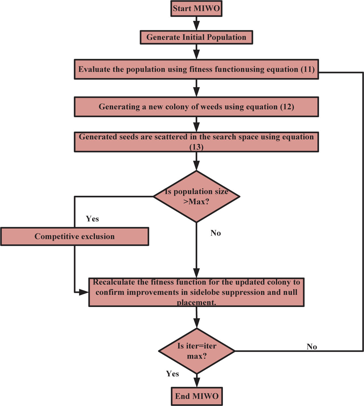
Figure 3:
Flowchart for MIWO algorithm.
c.ii. Modification with Laplace distribution
In a typical IWO, the offspring are dispersed about the parent weeds according to a Gaussian distribution. Gaussian perturbation can result in premature convergence and inadequate exploration in multimodal landscapes. In order to address this issue and to enhance the algorithms performance for achieving deep nulls, reducing side lobes, and maintaining stable adaptive performance in antenna array pattern synthesis. The Laplace distribution has heavier tails compared to the Gaussian allowing the seeds to more thoroughly explore larger search spaces in the first little iteration and then focus it search locally in further iterations. The revised dispersal rule for the new candidate positions is as follows:
Where μ denotes the standard deviation controlling the spread of seeds and L(0,1) represents a Laplace distributed random variable with a mean of 0 and scale parameter 1. The Laplace variable is computed using a uniformly distributed random number ν ~ V(−0.5,0.5) as follows:
From the above equation, c is the scalable parameter, generally set to 1 for unit scaling. This distribution model provides a higher probability of generating distinct offspring, enhancing global search efficiency. The Laplace distribution is given by,
From the above equation, the center of the parent position is denoted by φ, the scale parameter controlling the speed is c, and the uniform random variable is denoted by ν. The MLIWO algorithm works by repeatedly creating and assessing groups of candidate weight vectors, evaluates their performance and updates the vectors through successive iterations until the weight configuration ωOPT that best meets the fitness function is obtained.
d. Null forming and signal combination stage
In the null forming and signal combination stage, the optimized weights from the adaptive weight calculation stage are applied to each element of the antenna array [33]. Each element’s signal is adjusted according to its weight and all signals are then combined to produce the overall beamformed output that improves the desired signal, suppresses the interference sources, and minimizes the background noise. This process involves two tightly coupled operations: i) Null-forming, which enforces spatial suppression of interfering signals and ii) signal combination, which coherently combines signals from all antenna elements to reinforce the desired direction.
Null forming is a technique used in adaptive antenna arrays to intentionally create deep reductions or nulls in the antenna’s radiation pattern. The angular positions of interference or jamming signals are aligned with these nulls. Let β(θ) represent the steering vector for an angle based signal. The AF represents the array output in any direction (AF):
The array elements are subjected to an optimized weight vector denoted by .
The following requirement needs to be met to impose nulls at interference directions:
The term (θj) signifies the angles related to interference or jamming sources. This condition guarantees that the optimized weight vector shapes the beam pattern appropriately and suppresses energy from those unwanted directions. At the same time, the main lobe should maintain full gain in the desired signal direction at angle θδ. The requirement is expressed in the unity gain constraint:
In order to provide a strong reception of the target signal while successfully rejecting interference, the beam former maximizes the SINR by concurrently satisfying the null forming and unity gain conditions.
d.i. Spatial filtering interpolation
From the viewpoint of spatial signal processing, null forming can be viewed as spatial filtering. Each antenna element receives the delayed version of impinging signals according to its spatial context. The adaptive weighting of the received signal phase and amplitude is modified in such a way to accomplish the following: desired signals add constructively (in-phase). Interference signals add destructively (out-of-phase).
As soon as the required nulls are created to reduce interference, the signals acquired by all array elements are linearly summed together using a set of optimal weights. The beam former output z(τ) can be expressed as:
Where y(τ) = [y1(τ), y2(τ),…yM(τ)]T denotes the input signal vector containing the time domain signal captured by every sensor in the array ωOPT = [ω1, ω2,…,ωM]T. In this case, the complex weight vector is optimized, here using the maximum likelihood indication to waves in the open method to get the specified beam pattern, which optimally combines all the signals arriving from the desired direction to generate high array gain, while the signals arriving from the interference directions are combined destructively to minimize their effects greatly. As a result, z(τ) represents the digitized, interference-suppressed version of a target signal, suitable for the subsequent processing tasks such as detection or demodulation.
d.ii. Array factor and beam pattern analysis
The AF showing the resultant beam pattern directly shows the success of signal combination and null forming in an adaptive antenna array. The beam pattern magnitude in all directions θ is calculated as follows:
The performance of the adaptive array is analyzed according to three main characteristics of the beam pattern. The primary lobe indicates the maximum gain and location of the desired signals centered at the signal direction θδ. The deep minima (zero response locations) were purposely placed at the interference direction θj to suppress unwanted interfering signals as much as possible. The amplitude of the secondary (side lobes) was also carefully controlled to help minimize the reception of undesired signal direction and make sure that desired signals would not be leaked. Beam quality, including main beam width (beam width) as well as depth of the nulls, depends on the physical design of the array, like aperture size and element spacing, as well as the optimization of the weight vector.
e. Clean signal output generation
The final output provides a clear interference-free signal which will improve the accuracy and reliability of systems requiring radar tracking, target detection, and communications [34]. A continuous adaptation mechanism is inserted into the process, allowing for a stable performance in unpredictable dynamic environments. This loop detects changing conditions (moving interference sources or shifting noise levels) and adapts the beam forming weights in real time. Dynamic re-optimization allows the system to maintain consistent interference rejection and high signal quality. With automatic adaptation to changing environments, the model retains significant robustness against time-variant interference. Continuous feedback supports signal fidelity and system robustness in complex environments. In contrast to standard non-distributed beam formers, it supports flexible intelligent responses in the face of external disturbance. The method will ultimately produce precise and resilient beam forming for reliable communication and detection capability.
f. Adaptation loop and dynamic re-optimization
In reality, defense and radar systems frequently operate in dynamic electromagnetic environments where the sources of interference, movement of the targets, or channel noise are constantly changing [35]. The systems utilize a closed-loop adaptive re-optimization mechanism to achieve continuous interference suppression and main lobe preservation, known as the Adaptation Loop. Adaptation loops continuously monitor key environmental and performance indicators, including the DoA changes indicated by MUSIC or ESPRIT algorithms, power levels of the interference and jammers, changes in the signal-to-noise ratio (SNR), changes in the arrays calibration, and propagation conditions. These inputs are processed in real time to assess whether the system performance has diverged from optimum.
f.i. Triggering criteria for re-optimization
The system contains an adaptive feedback loop that tracks array performance and activates the MLIWO module to recalculate the array weights whenever a significant degradation in one of the critical metrics is detected. Examples of such degradation include lower signal to interference plus noise ratio (SINR) values shifts in the main lobe angle or changes in ND. Re-optimization commences when it meets the condition.
According to the equation above, A defines the user-specified threshold that quantifies maximum allowable performance reduction. This adaptive process was intended to improve the computational performance of the agent by only invoking the computationally expensive weight optimization when the need to preserve system performance is significant.
f.ii. Dynamic weight re-optimization
The suggested MLIWO module uses the most recent data regarding the signal environment to calculate an updated weight vector upon activation. The following is how the revised vector was expressed:
Based on the above equation, ℜNEW is the most recent covariance matrix calculated from the data received to the array from the signals. Both b(θδ) and b(θj) are the steering vectors that correspond to the desired signal and the direction of interference respectively. This operation allows the algorithm to quickly adapt as new interference sources change positions or characteristics all the while still being capable of converging to a globally optimal solution.
IV. Results and Discussion
The performance of the suggested system is assessed through several performance metrics which can assess its capabilities of interference suppression and signal quality. ND is a metric of interference suppression and SLL gives an insight into unwanted radiation suppression. There are parameters such as BW and main lobe integrity metrics that ensure limits of signal accuracy and quality and there are measures of improvement such as SINR and array gain. Speed of convergence, computations, and robustness are also evaluated to prove the real-time applicability of the system across different environments. The proposed framework was developed and tested in MATLAB and the results confirmed that the MLIWO algorithm effectively produces deeper nulls in the far field region and a side lobe suppression capability while successfully adapting in a dynamic environment as such, it is a reliable solution for interference suppression and optimization for advanced communication and radar applications. Table 2 lists the specifications of each parameter.
Table 2:
Parameter specifications
| Parameter | Value | |
|---|---|---|
| 1 | Maximum number of seeds | 5 |
| 2 | Minimum number of seeds | 0 |
| 3 | Initial standard deviation | 0.1 |
| 4 | Final standard deviation | 0.00015 |
| 5 | Maximum population size | 20 |
| 6 | Number of iterations for local search | 3 |
| 7 | Initial population size | 10 |
Figure 4 shows the radiation pattern of a 10-element linear array, comparing a conventional ULA with the pattern optimized using the MLIWO algorithm. Both patterns are centered at 0°, but the proposed MLIWO optimized array achieves deep nulls at the interference angles of 24° and −31°, whereas the ULA only displays standard sidelobes. The MLIWO pattern also maintains lower sidelobe levels overall, effectively suppressing unwanted signals. This demonstrates that MLIWO enhances beam shaping and precise null steering improving interference mitigation and overall signal quality.
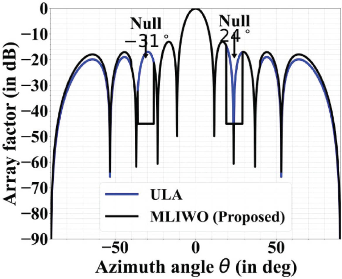
Figure 4:
Radiation pattern analysis of a 10-element linear array with nulls at 24° and −31°. ULAs, uniform linear arrays.
Figure 5 illustrates the optimized amplitude and phase settings for a 10-element linear array, designed to produce a radiation pattern with nulls at 24° and −31°. Two sets of values is plotted against the element numbers from 1 to 10: the Taylor amplitude distribution and the optimized phase values. The amplitude distributions are tapered with maximum amplitude at the central element decreasing beyond the center reducing SLLs from the outer edges of the array. The phase values applied to the elements are also varied over all elements to accurately position deep nulls at specific angles. The more complex phase variation is crucial for proper null steering. In addition the tapered amplitude creates total side lobe suppression for improved signal reception. Combined these amplitudes and phase settings define how each element contributes to the array’s radiation pattern. The arrangement allows the array to maintain a strong main beam while minimizing interference. Overall, the figure demonstrates how the MLIWO algorithm optimizes both amplitude and phase for improved pattern control.
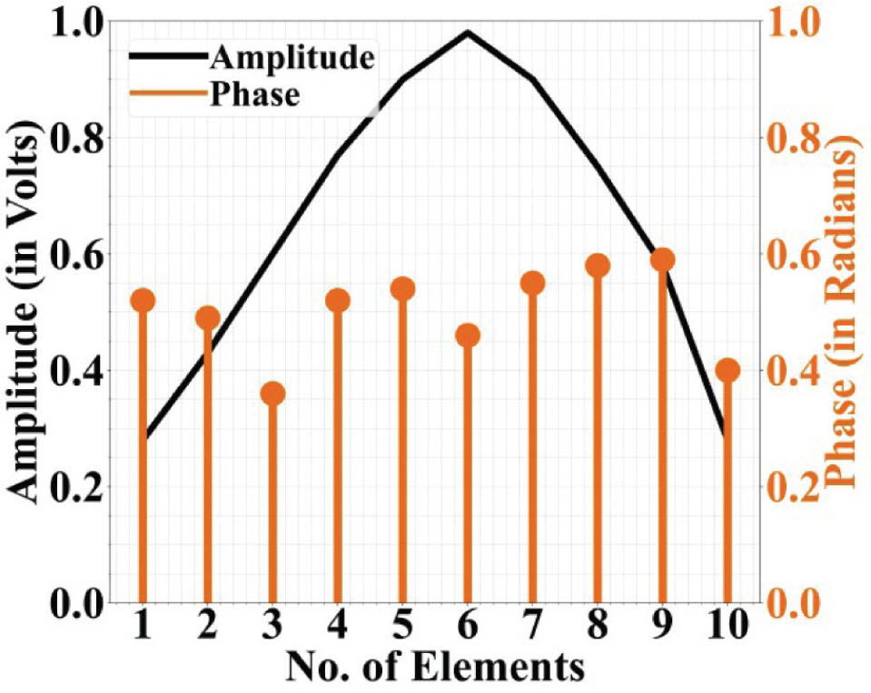
Figure 5:
Optimized phase values and Taylor amplitude distribution for a 10-element linear array with nulls at 24° and −31°.
Figure 6 depicts the convergence behavior of the MLIWO algorithm on the 10-element linear array. It is a plot of the Best Fitness Value against the Number of Generations. In this regard, the fitness value is a measure of how well a given solution performs in achieving objectives, and the lower value is better in terms of good performance, for example, lower sidelobes and deeper nulls. The curve starts at a comparatively high value of fitness, which represents the beginning unoptimized condition. The decline in fitness is steep between roughly 300 and 500 generations, as it shows that the algorithm rapidly identified significantly better solutions very early on. Beyond 500 generations, improvement tapers off and the curve slowly levels out toward zero. By the 1000th generation, fitness value is close to its minimum, indicating the algorithm has converged to an optimal or near-optimal solution for amplitude and phase settings of the array. The convergence plot validates the reliability and efficiency of the MLIWO algorithm for synthesizing accurate the radiation patterns with deep null placement.
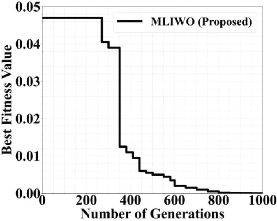
Figure 6:
Convergence plot for a 10-element linear array using MLIWO.
Table 3 depicts that the proposed MLIWO algorithm was converged the about 35% faster than the GA and 22% faster than the IWO, demonstrating the enhanced computational efficiency. The Laplace distributions adoption successfully enhances the ratio of exploration to exploitation reducing computational load while preserving optimization stability. Notably, MLIWO reached the convergence in just 520 iterations, whereas GA, PSO, CSO, and IWO required between 680 and 800 iterations under the same conditions. This reduced iteration is count to highlights the algorithm’s superior convergence rate, mainly due to the Laplace-based mutation mechanism that promotes wide exploration initially and fine-tuned exploitation near the optimum. Therefore, MLIWO efficiently achieves the desired beam pattern with fewer computations, making it highly suitable for real-time interference suppression and adaptive array optimization.
Table 3:
Runtime and convergence comparison of optimization algorithms (10-element array)
| Algorithm | Runtime (s) | Iterations to convergence | Best fitness value | Improvement over GA (%) |
|---|---|---|---|---|
| MLIWO | 12.48 | 520 | 0.0023 | +35.7 |
| IWO | 15.93 | 680 | 0.0042 | +18.6 |
| PSO | 17.81 | 720 | 0.0051 | +10.5 |
| CSO | 18.12 | 740 | 0.0048 | +12.2 |
| GA | 20.32 | 800 | 0.0063 | Baseline |
Table 4 shows the comparison of the results synthesized for 10-element linear array by a five algorithms, namely MLIWO, IWO, crow search optimization (CSO), particle swarm optimization (PSO), and genetic algorithm (GA). The lowest peak side lobe level (PSLL) is seen in MLIWO at −24.01 dB, which depicts better sidelobe suppression than the other algorithms. The null at 310° is deepest for MLIWO at −78.92 dB, indicating extremely efficient interference rejection. Likewise, the null at −45°indicates the best suppression by MLIWO at −70.59 dB. IWO and CSO have moderate performance, while PSO and GA exhibit relatively higher sidelobe levels and more shallow nulls. As a whole, the table indicates that MLIWO performs better than the other algorithms in both sidelobe cancellation and deep nulling. This establishes the efficacy of MLIWO for obtaining accurate beam shaping and interference mitigation in linear arrays.
Table 4:
Comparison of the synthesized results of a 10-element linear array
| Parameter | MLIWO | IWO | CSO | PSO | GA |
|---|---|---|---|---|---|
| PSLL (in dB) | −24.01 | −21.05 | −20.83 | −19.85 | −18.10 |
| Null at 31° (in dB) | −78.92 | −75.25 | −69.56 | −70.11 | −65.84 |
| Null at −45° (in dB) | −70.59 | −65.17 | −68.54 | −65.89 | −62.85 |
Figure 7 shows the radiation patterns of a 20-element linear array with the main beam steered to 23° and nulls located at −10° and −42°. Three methods are compared: the standard uniform isotropic linear array (UILA), UILA with Bayesian filtering (BF), and the proposed MLIWO. The three methods all steer the main beam to the desired angle successfully. However, the MLIWO-optimized pattern has obvious benefits. It creates the deepest nulls in the desired interference directions, hugely minimizing the array’s sensitivity to the undesired signals. Furthermore, the overall sidelobe levels are lower in the MLIWO pattern compared to both UILA and UILA with BF, especially in off-main-beam regions. These outcomes show that MLIWO efficiently addresses the combined problems of beam steering, accurate null placement, and sidelobe suppression.
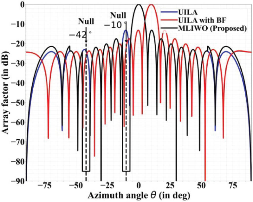
Figure 7:
Radiation pattern of a 20-element linear array with 23° beam steering, and nulls at −10° and −42°. UILA, uniform isotropic linear array; BF, Bayesian filtering.
Figure 8 shows the amplitude and phase optimized settings for the 20-element linear array with the goal of beam steering to 23° and nulls at −10° and −42°. Amplitude distribution is tapered along the profile, its peak value occurring at the center elements and declining smoothly toward the edges. This taper is necessary to obtain low sidelobe levels in the radiation pattern. Phase values are non-uniform and asymmetric over the array, indicative of the complex phase adjustments to steer the main beam and place deep nulls accurately. The phase values for most elements are all positive with the last element experiencing a significant negative shift demonstrating the nature of simultaneous beam and null steering. The tapered amplitude with the complex phase provides a solid placement for the null and robust integrity of the main beam. These optimized tapers were generated using the MLIWO algorithm. These are important in order to obtain sophisticated pattern control and effective interference suppression, showing the capability of the algorithm in dealing with huge and intricate arrays.
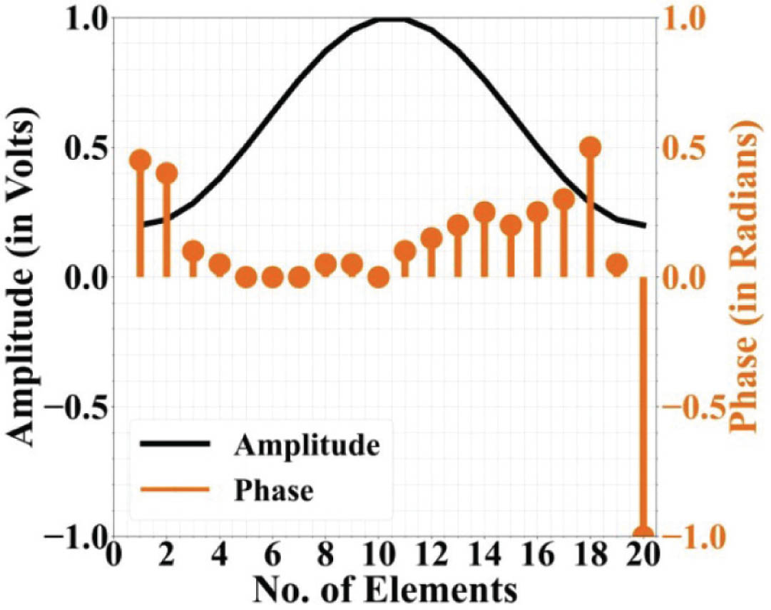
Figure 8:
Optimization of phase and Taylor amplitude distribution for a 20 element linear array with 23° beam steering and nulls at −10° and −42°.
Figure 9 indicates the convergence behavior of the MLIWO algorithm on a 20-element linear array. The graph plots the Best Fitness Value—lower values translating to improved performance, that is, deeper nulls and lower sidelobes—against the Number of Generations. Optimization starts from a high value of about 0.11, corresponding to the non-optimized state. The curve decreases gradually, with very fast advancements noted in the initial 700 generations, demonstrating the algorithm’s capability of finding better solutions at a fast rate. The step-wise reduction reveals that the technique continues to optimize the solution without getting stuck. In the 1000th generation, the fitness value is almost zero, indicating that MLIWO has successfully converged to an optimal or close-to-optimal arrangement. This plot demonstrates the algorithms effectiveness and stability in the challenging task of beam steering and null placement for large linear arrays at the same time.
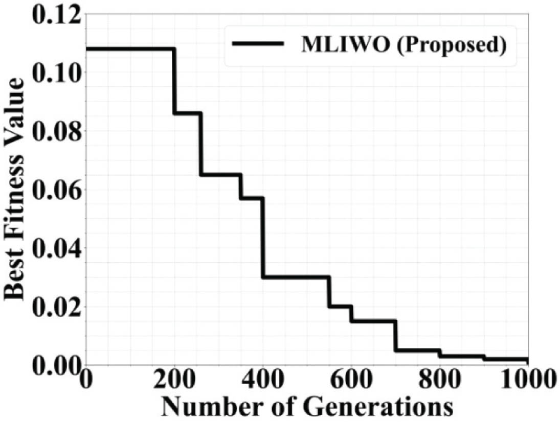
Figure 9:
Convergence plot for a 20-element linear array using MLIWO.
Table 5 compares results which were synthesized by a 20 element linear array optimized by five algorithms; MLIWO, IWO, CSO, PSO, and GA. All methods produce the same beam steering of 230° indicating a proper alignment of the main beam. The PSLL is minimum with MLIWO at −21.80 dB, exhibiting better sidelobe suppression than the other algorithms. The ND at −10° is maximum with MLIWO at −80.75 dB, indicating excellent interference rejection capability. Likewise, the null at −42° is maximum with MLIWO at −88.87 dB. IWO and CSO exhibit mediocre performance, whereas PSO and GA have greater sidelobe levels and shallower nulls. In general, the table indicates that MLIWO offers the optimum balance of beam steering, deep null positioning, and sidelobe minimization. This verifies the effectiveness of the algorithm for advanced large-array pattern synthesis.
Table 5:
Comparison of synthesized results of a 20 element linear array
| Parameter | MLIWO | IWO | CSO | PSO | GA |
|---|---|---|---|---|---|
| Beam steering (in Deg) | 23° | 23° | 23° | 23° | 23° |
| PSLL (in dB) | −21.80 | −19.41 | −19.82 | −18.20 | −17.52 |
| Null at −10° (in dB) | −80.75 | −71.41 | −72.84 | −69.58 | −61.47 |
| Null at −42° (in dB) | −88.87 | −74.58 | −69.74 | −65.24 | −62.32 |
Figure 10 is a comparative radiation pattern of a 100-element linear array in a challenging beam-steering case with a sector null. The main beam points to −41° and there must be a deep null within the angular sector of 31° and 40° to reject widespread interference. Three techniques are compared: the standard UILA, UILA in conjunction with BF, and the newly proposed MLIWO. The MLIWO-optimized pattern readily outperforms the others, delivering a smooth and deep null across the entire 31° and 40° sector, efficiently reducing interference. In addition, the MLIWO solution has lower sidelobe levels away from the main beam and null regions than with the other methods. These findings illustrate the performance of the algorithm in dealing with big arrays and performing sophisticated pattern synthesis. Specifically, MLIWO effectively accomplishes the difficult task of wide sector nulling without sacrificing main-beam integrity. This attests to its ability for reliable interference mitigation in realistic array geometries.
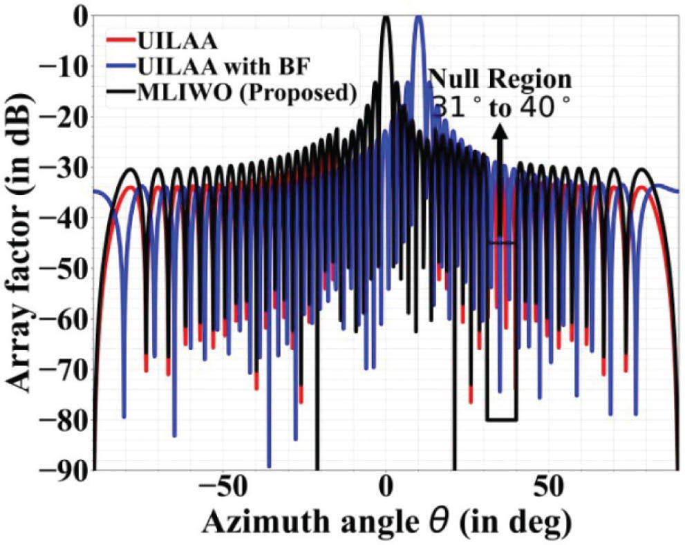
Figure 10:
Radiation pattern analysis of a 100 element linear array with −41° beam steering, and sector null in the angular region of 31° and 40°. UILA, uniform isotropic linear array; BF, Bayesian filtering.
Figure 11 shows the optimized amplitude and phase values for the 100-element linear array that is configured to produce beam steering to −41° in combination with a sector null of 31° and 40°. The amplitude pattern is tapered in shape, reaching its peak value around the central elements (element 50) and diminishing gradually toward the periphery. This tapering, as in the case of Gaussian or Blackman−Harris windows, ensures low sidelobe levels for the array. The phase values are strongly non-uniform, asymmetrical, and significantly varied over all elements. Such intricate phase adjustments are required to control the high density of elements while at the same time controlling the main beam and establishing a broad sector null. The scattered yet accurate phase distribution permits effective interference suppression over the defined sector. In combination, the tapered amplitude and complex phase patterns facilitate sophisticated radiation pattern control. These configurations were established by the MLIWO algorithm, proving its ability to optimize large arrays for demanding beamforming and null-steering applications.
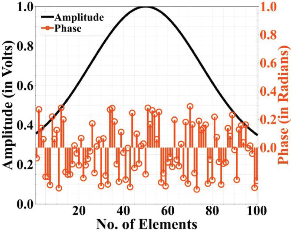
Figure 11:
Phase and amplitude optimization of a 100-element linear array with −41° beam steering, and sector null in the angular region of 31° and 40°.
Figure 12 is the plot of the convergence of the MLIWO algorithm on the 100-element linear array for sector nulling and beam steering. The figure plots the Best Fitness Value against the Number of Generations, where smaller values are a sign of better optimization, for example, deeper nulls and smaller sidelobes. First, the fitness value remains close to constant at approximately 0.27 up to generation 600, indicating a stage of exploration of the extensive solution space. From approximately generation 650 onward, the fitness value plunges, which suggests that the algorithm has found a much better area in the search space. This improvement at a high rate goes on until generation 900 or so. At the 1000th generation, the value of fitness is close to a minimum value close to 0.02, indicating that the algorithm has converged suitably. Due to the complexity of the large array and the challenging problem of simultaneous beam steering and wide-sector nulling, MLIWO is able to find an optimum or near-optimum solution. This plot verifies the robustness and efficacy of the algorithm in solving large-scale complex array optimization problems.
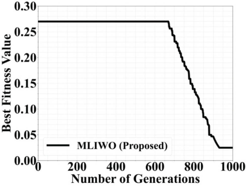
Figure 12:
Convergence plot for a 100-element linear array using MLIWO.
Table 6 shows a comparison of synthesized results for a 100-element linear array with five optimization algorithms, namely MLIWO, IWO, CSO, PSO, and GA. All the methods are able to successfully align the main beam to −41°, showing steady beam alignment. PSLL is minimal at −26.75 dB for MLIWO, reflecting the best sidelobe rejection capability among the algorithms. The 31°–40° sector null develops the deepest level with MLIWO at −65 dB, reflecting the best interference rejection within the designated sector. IWO and CSO render moderate performance, while PSO and GA have larger sidelobes and shallow sector nullsIn general, the table shows that MLIWO performs better than other algorithms for both sidelobe reduction and wide-sector null formation. This verifies the algorithm is able to work with large arrays and achieve the sophisticated pattern synthesis.
V. Conclusion
The research demonstrates the superior performance of the proposed MLIWO algorithm in the synthesis of radiation patterns using differently sized linear arrays including 10, 20, and 100 element arrays. In all of the configurations, MLIWO outperformed conventional optimization algorithms (IWO, CSO, PSO, and GA) with respect to several important performance indices (including PSLL, deep null placement, and wide sector null). The MLIWO effectively pointed the main beam to desired angles while also being able to place nulls at the predetermined directions of interference with significant suppression of interference. Tapered amplitude profiles reduced SLLs while the strongly non-uniform and asymmetric phase profiles facilitated the accurate simultaneous control of beam steering and null placement. The convergence plots established that MLIWO quickly found the optimal or near optimal solutions in all cases including for the large arrays while avoiding stagnation which shows both efficiency and adaptive stability. The method does have some limitations such as increased computational complexity associated with the large arrays and its sensitivity to tuning of parameters to reach peak performance. A potential avenue for future research includes combinations of this algorithm in systems with real time adaptive feedback with hybrid optimization methods and with extensions to plan circular or conformal arrays. In conclusion the MATLAB simulations indicate that the proposed MLIWO is a highly competent, adaptable, and scalable solution for advanced radar and communication technology producing superior signal quality, improved ND, reduced side lobes, and stable adaptive performance.
Acknowledgments
None.
Notes
[8] Compliance with Ethical Standards
Potential conflict of interest disclosure:
None of the authors have any potential conflicts of interest.
Declaration on human and animal rights:
Ethical Approval: All relevant national and/or academic regulation for the use and care of animals was strictly adhered to.
Informed consent:
Formal consent is not essential for this particular type of research.