
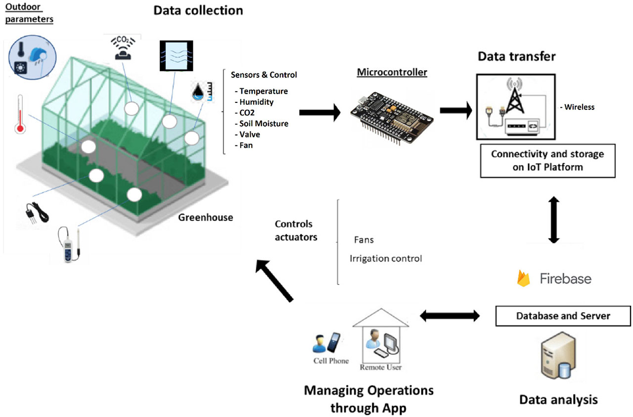
Figure 1:
Flow diagram of the proposed IoT-based framework. IoT, Internet of Things.
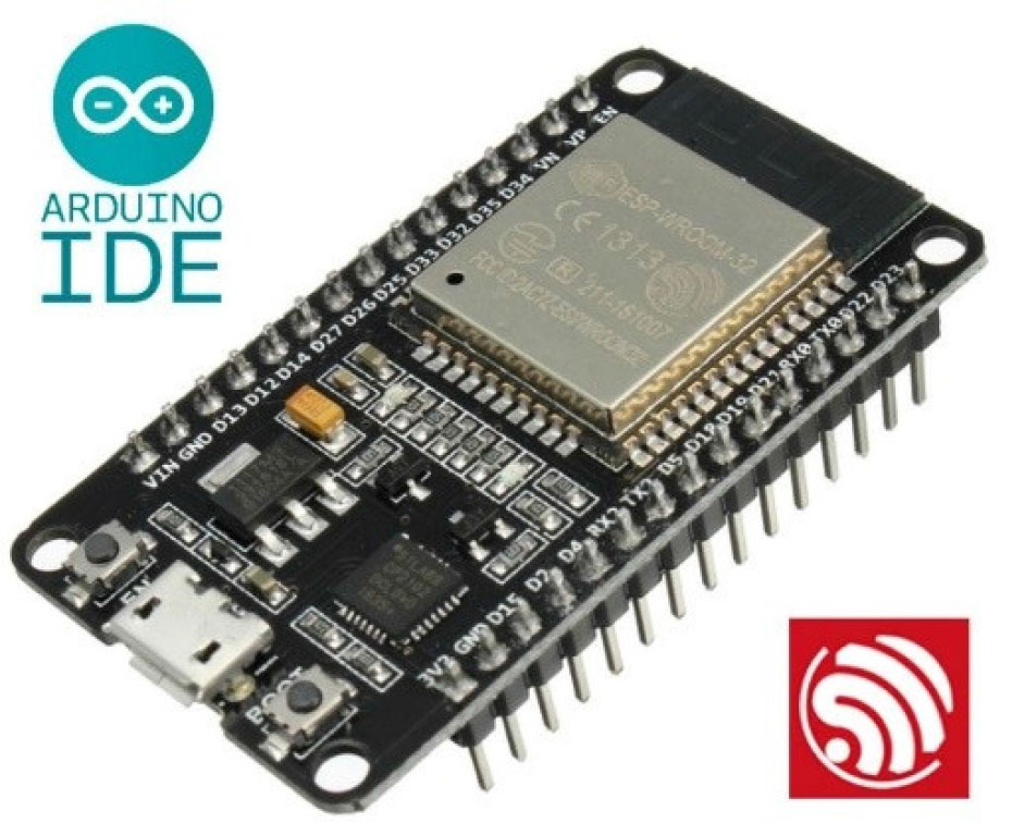
Figure 2:
ESP32 microcontroller.
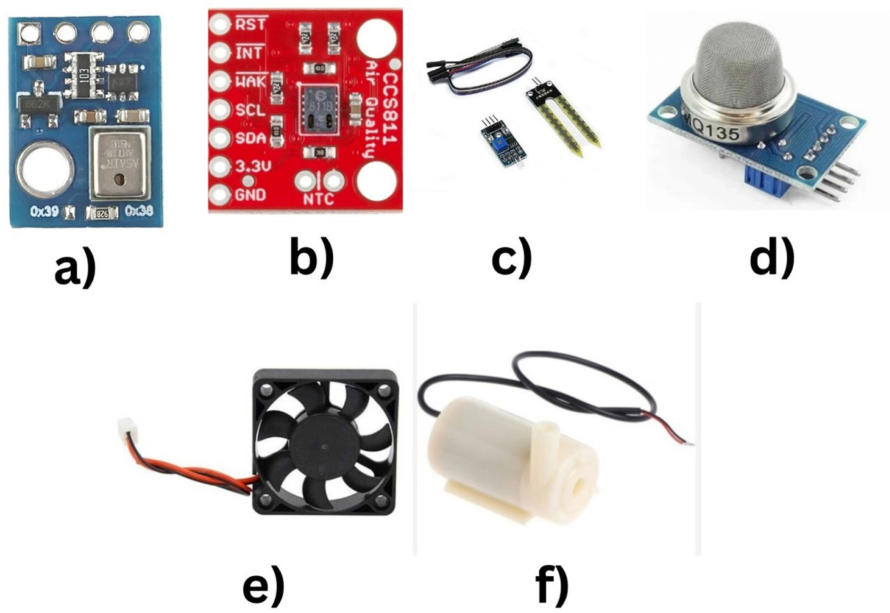
Figure 3:
Sensor and control actuators with the ESP32 microcontroller used for the proposed IoT framework: (A) AHT10, (B) CJMCU-811, (C) hygrometer, (D) MQ135, (E) fan, and (F) mini pump. IoT, Internet of Things.
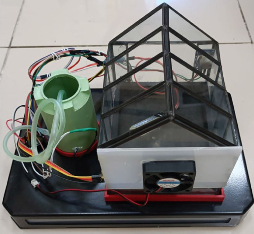
Figure 4:
Prepared smart greenhouse prototype.
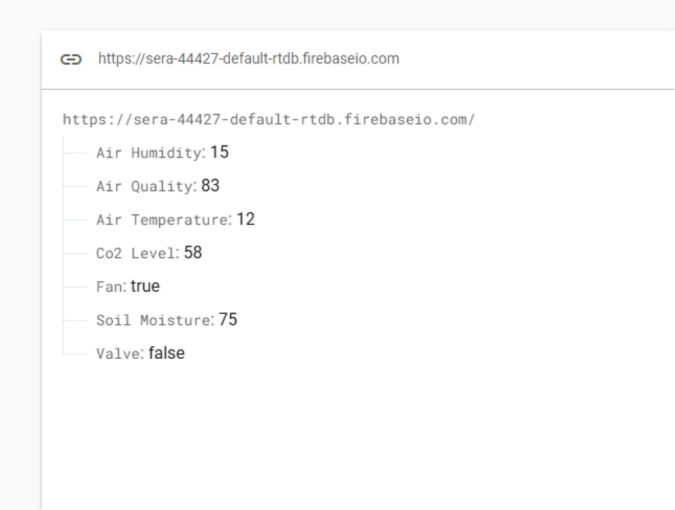
Figure 5:
Sensor values obtained from sensors used in the Smart Greenhouse Prototype, displayed on Google Firebase (Units of each sensor values: Air Temperature [°C], Air Humidity [%], CO2 Level [ppm], Soil Moisture [% Volumetric Water Content (VWC)], Air Quality [ppm], Fan On/Off [True/False], Mini Pump On/Off [True/False]).
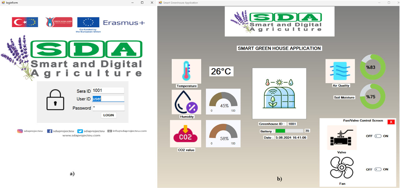
Figure 6:
Developed desktop application and its interfaces: (A) Login interface, (B) monitoring interface.
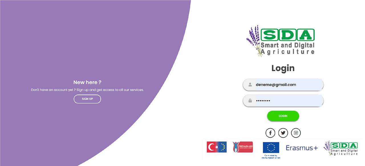
Figure 7:
Login interface of the developed Java-based web application.
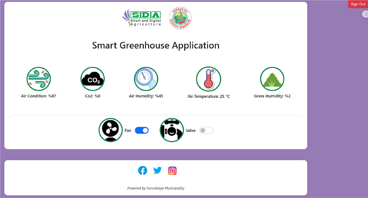
Figure 8:
Sensor value-based monitoring interface of the developed Java-based web application.
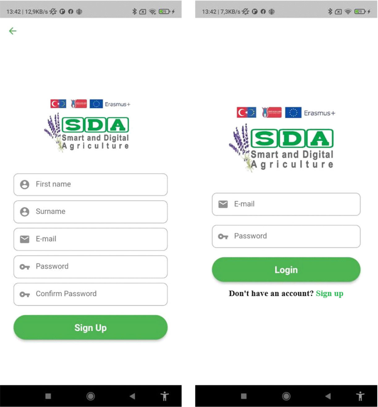
Figure 9:
Login and registration screens of the developed mobile application.
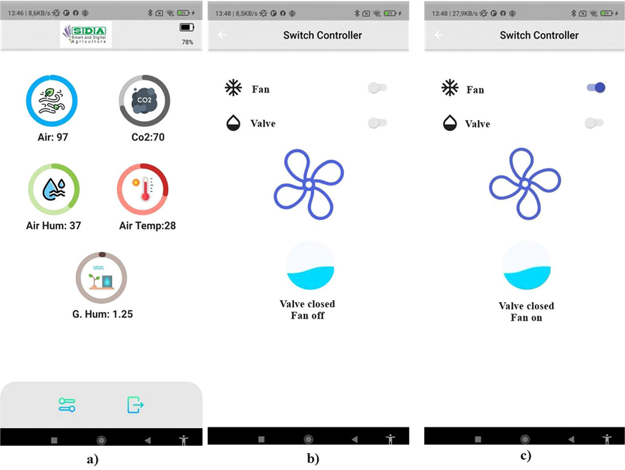
Figure 10:
Monitoring (a), and fan and valve control (b-c) screens of the developed mobile application.