
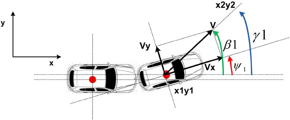
Figure 1
IoT Mobile Anchor Node (ex. Vehicle) angles. Where, β = sideslip angle, Ψ = orientation of vehicle, and γ = orientation of velocity.
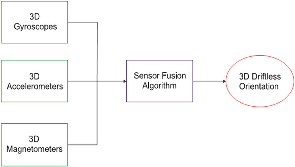
Figure 2
IMU sensor fusion.
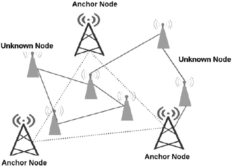
Figure 3
Outdoor Localization Mechanism for IoT Nodes.
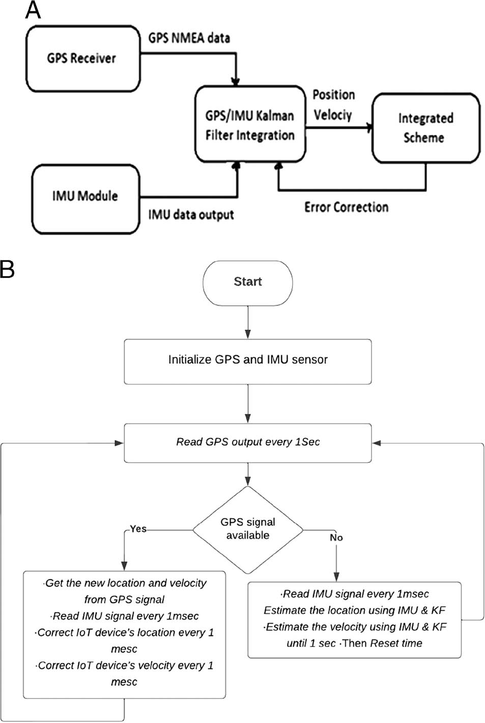
Figure 4
(a): Block diagram of the proposed method. (b): Flowchart of the proposed method.
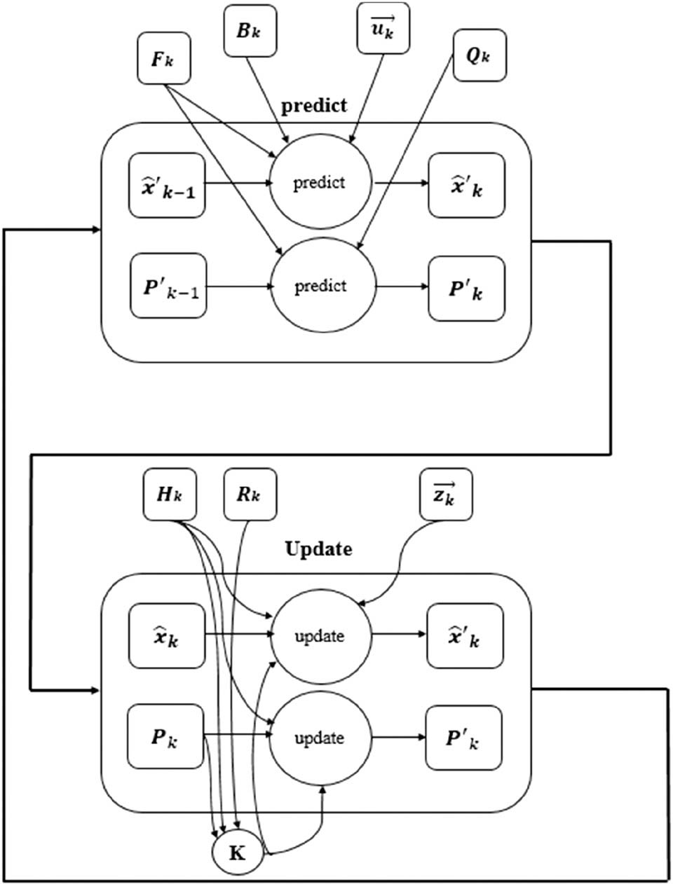
Figure 5
Flow diagram of the proposed method.
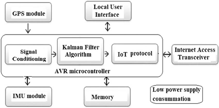
Figure 6
The proposed hardware Anchor IoT node.
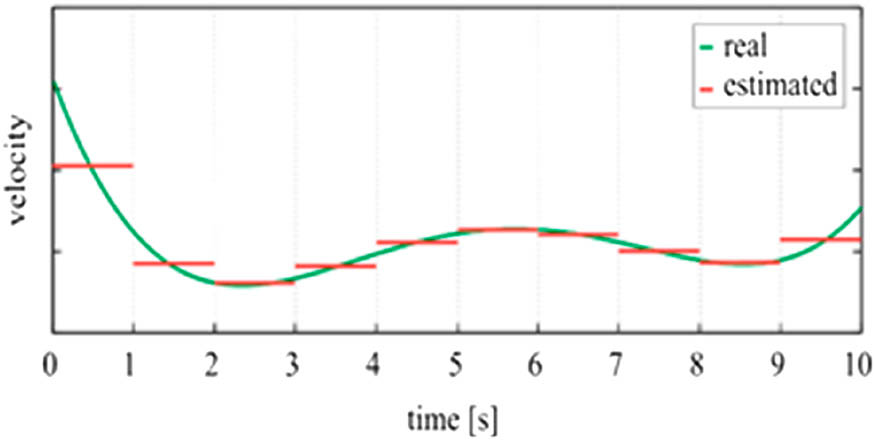
Figure 7
Real velocity versus calculated velocity.
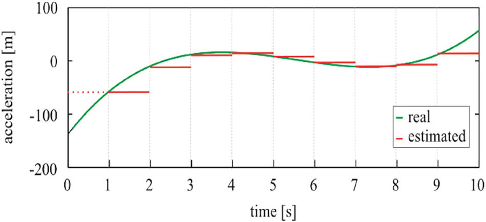
Figure 8
Example of a GPS' calculated acceleration.
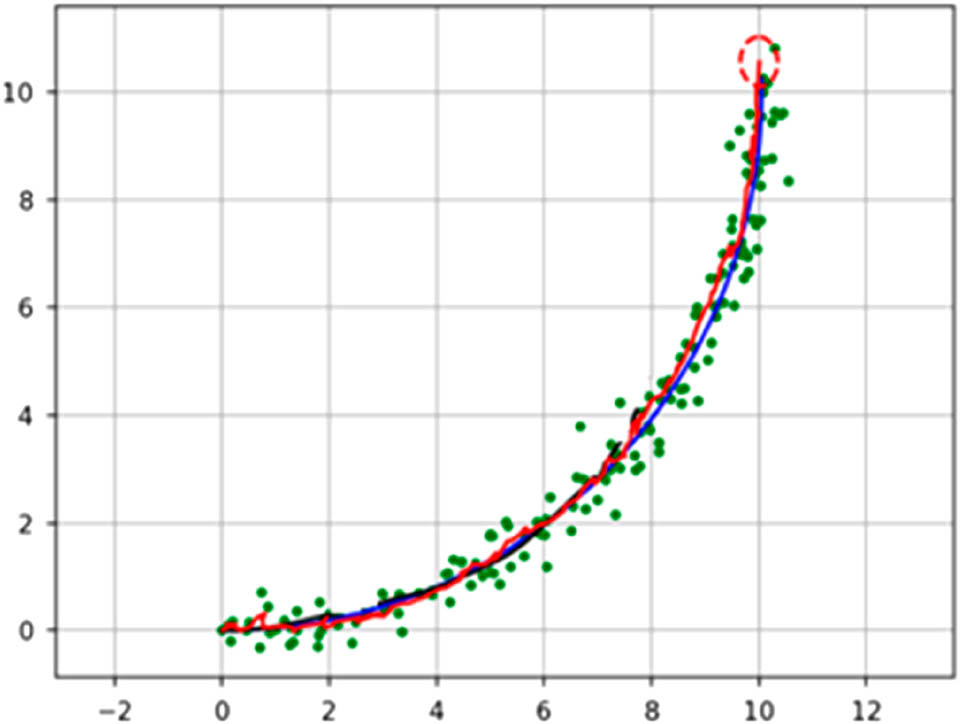
Figure 9
Error Metric Computation (Python simulation), where: Green points are GPS observation, Red line is estimated trajectory and Blue line is the true trajectory positions.
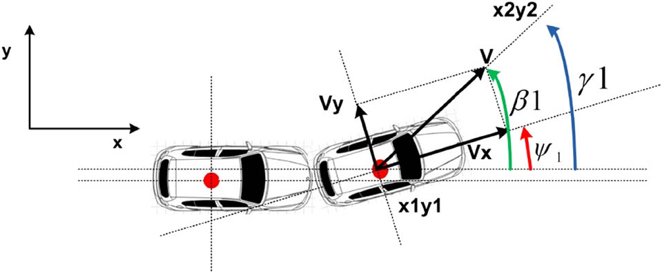
Figure 10
Hardware Work Flow realized on Logic Analyzer.
Table 1
Comparison between the proposed method and the relevant work.
| 2019 (Zhu et al., 2019) | 2016 (Werries and Dolan, 2016) | 2017 (Li et al., 2017) | Proposed Method | |
|---|---|---|---|---|
| GPS with IMU | Yes | Yes | Yes | yes |
| KF of modified KF | Yes | Yes | Yes | yes |
| Hardware implementation | No | No | No | yes |
| Update rate | Not mentioned | 250 m sec | Not mentioned | 10 m sec |
| Update location if GPS signal lost | No | No | No | yes |
| Integrate with IoT device | No | No | No | yes |
| Used Components | GPS + 3IMU | GPS | GPS + IMU + UWB | GPS + IMU |
| Power consumption (without microcontroller) | 79.2 + 3*10.56 = 110.88 mW | 79.2 mW | 79.2 + 10.56 + 5.3 = 95 mW | 79.2 + 10.56 = 89.76 mW |