
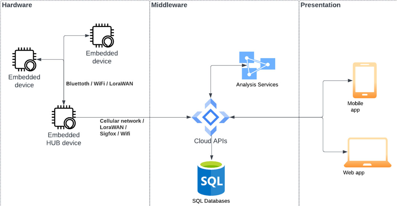
Fig. 1.
Concept of IoB system structure
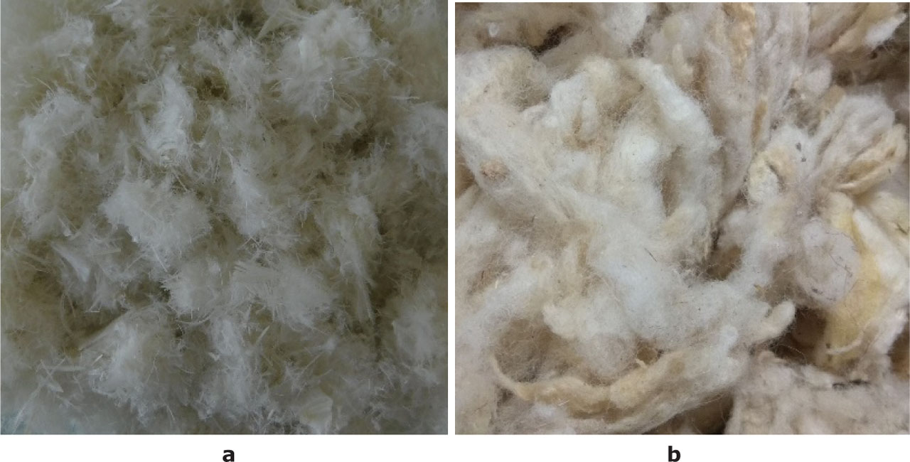
Fig. 2.
Chicken feathers (a) and wool (b)
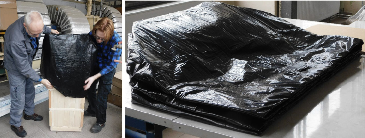
Fig. 3.
Thermal insulation cover
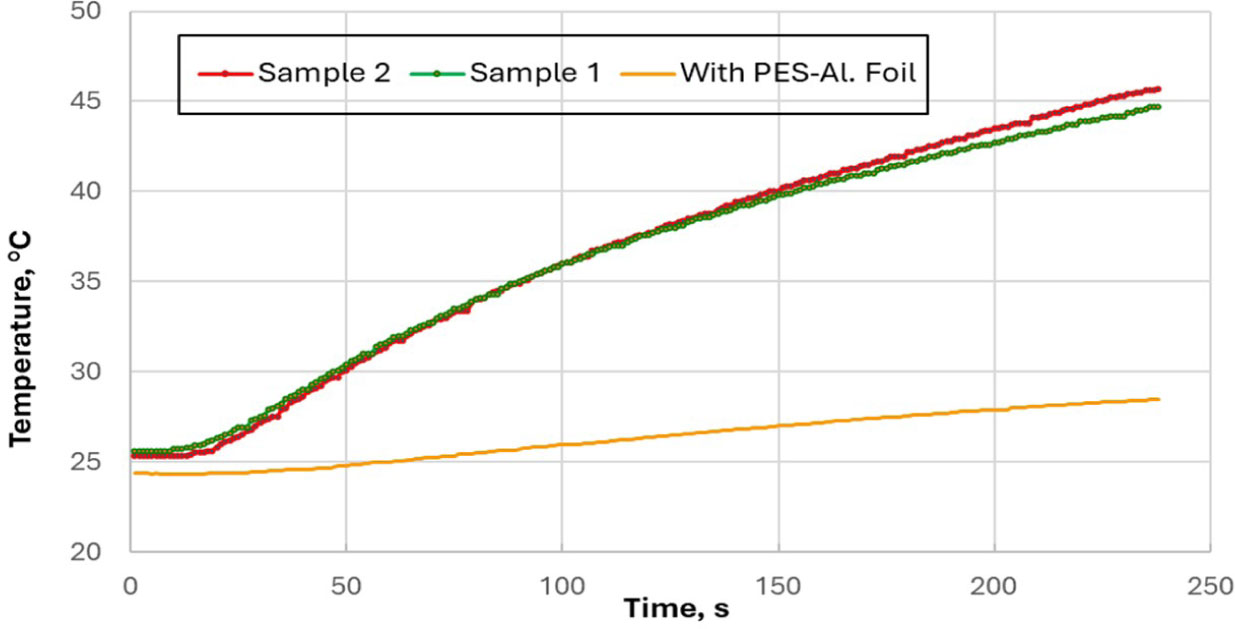
Fig. 4.
Temperature of the internal surfaces of composite nonwoven samples versus exposure time of their external surfaces to thermal radiation with a flux density of 3 kW/m2
Sample 1 – composite nonwoven sample; thermal radiation fell on the white foil
Sample 2 – composite nonwoven sample; thermal radiation fell on the black foil
With PES-Al. Foil – Sample 2 + aluminized PES foil; thermal radiation fell on the PES foil
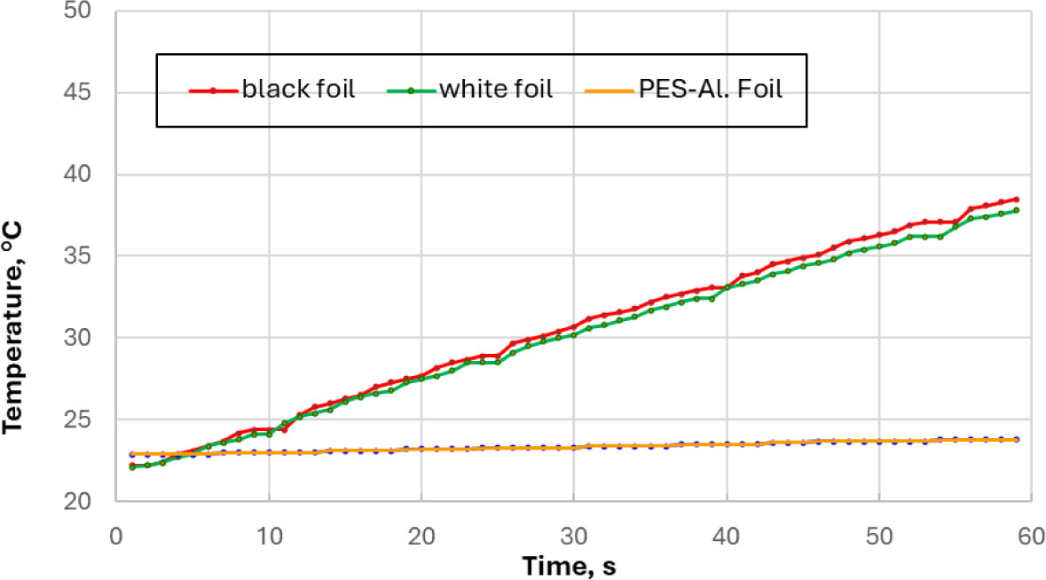
Fig. 5.
Temperature of the internal surfaces of foils samples versus exposure time of their external surfaces to thermal radiation with a flux density of 3 kW/m2
Table 1.
Values of indicators characterizing the thermal insulation of the systems tested
| Samples | Heat transfer level, t12, s | Heat transmission factor, |
|---|---|---|
| Nonwoven fabrics | ||
| Sample 1 | 120 | 0.19 |
| Sample 2 | 116 | 0.20 |
| PES-Al foil | after 120 s of exposure to thermal radiation, the temperature of the sample increased by 2.1°C | 0.05 |
| Foils | ||
| Black | 43 | 0.98 |
| White | 45 | 0.95 |
| PES-Al foil | after 45 s of exposure to thermal radiation, the sample temperature increased by 0.8°C | 0.06 |
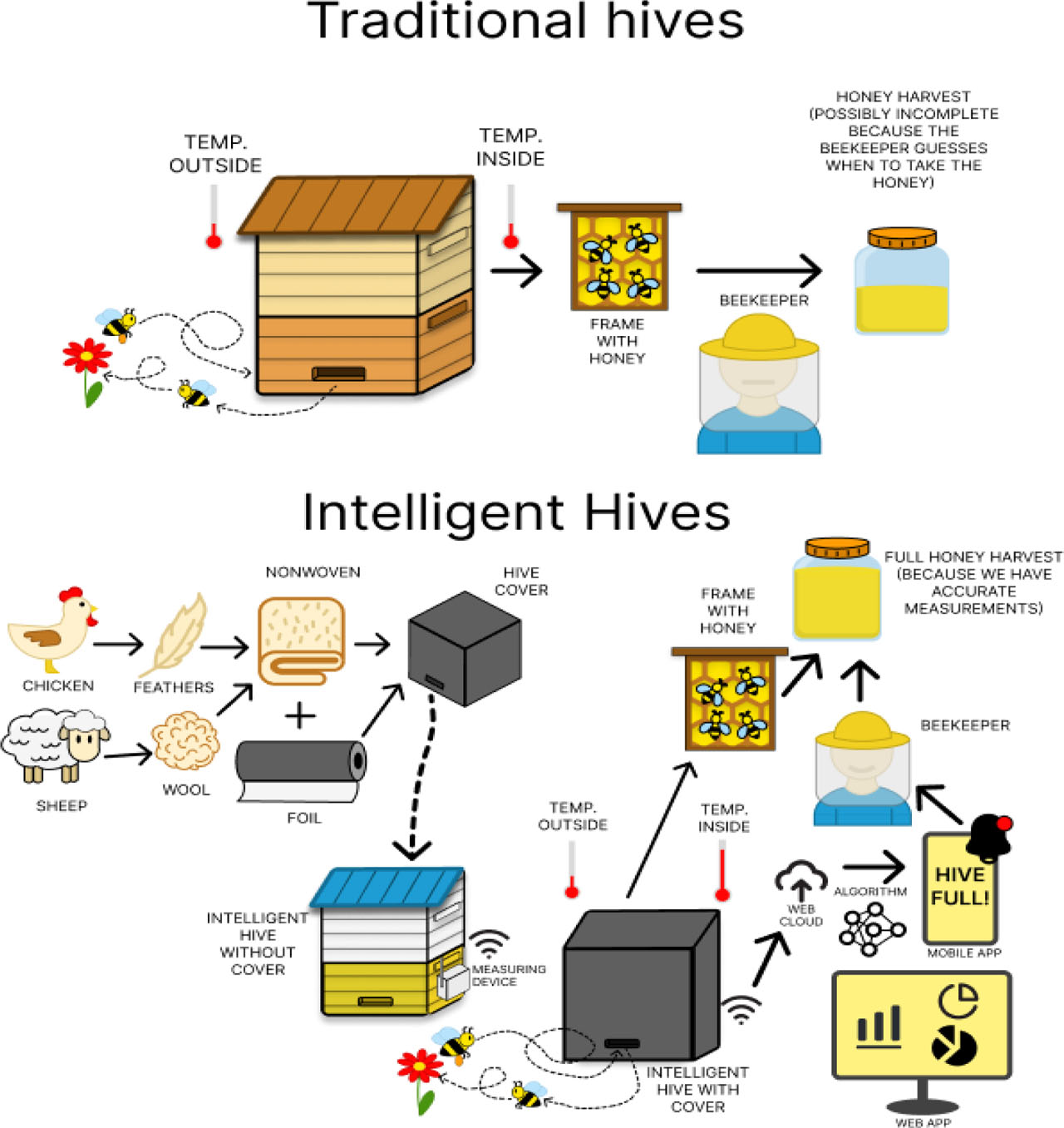
Fig. 6.
Diagram comparing the principle of operation of a traditional hive and intelligent hive
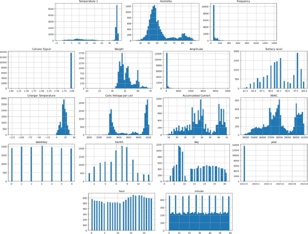
Fig. 7.
Seasonal analysis of hive parameters from an experimental beehive
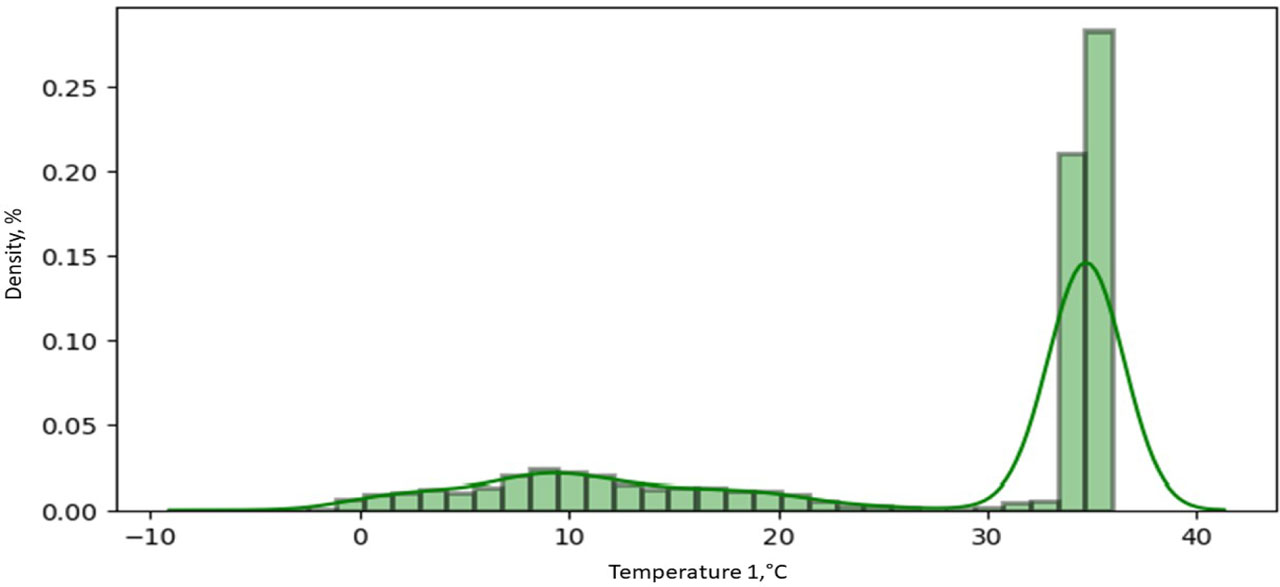
Fig. 8.
Density distribution of hive temperature measurements in experimental hive
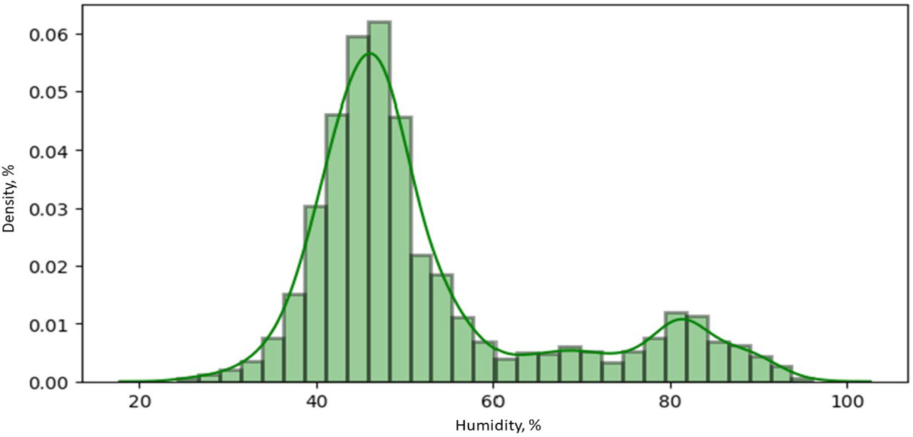
Fig. 9
Density distribution of hive humidity measurements in experimental hive
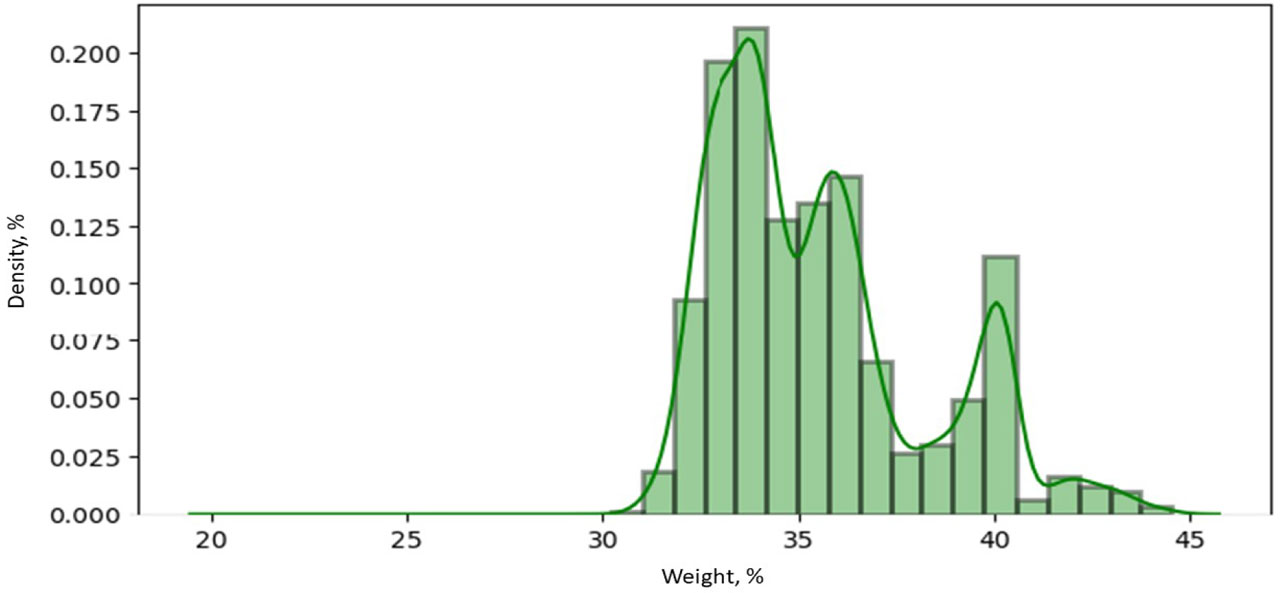
Fig. 10.
Density plot of beehive weight of experimental hive
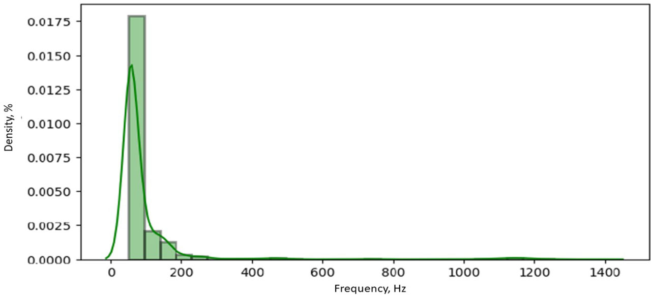
Fig. 11.
Density distribution of sound frequency in a beehive
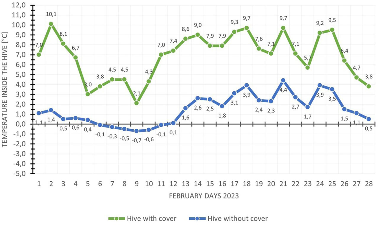
Fig. 12.
Comparison of temperatures inside the hive with and without covers
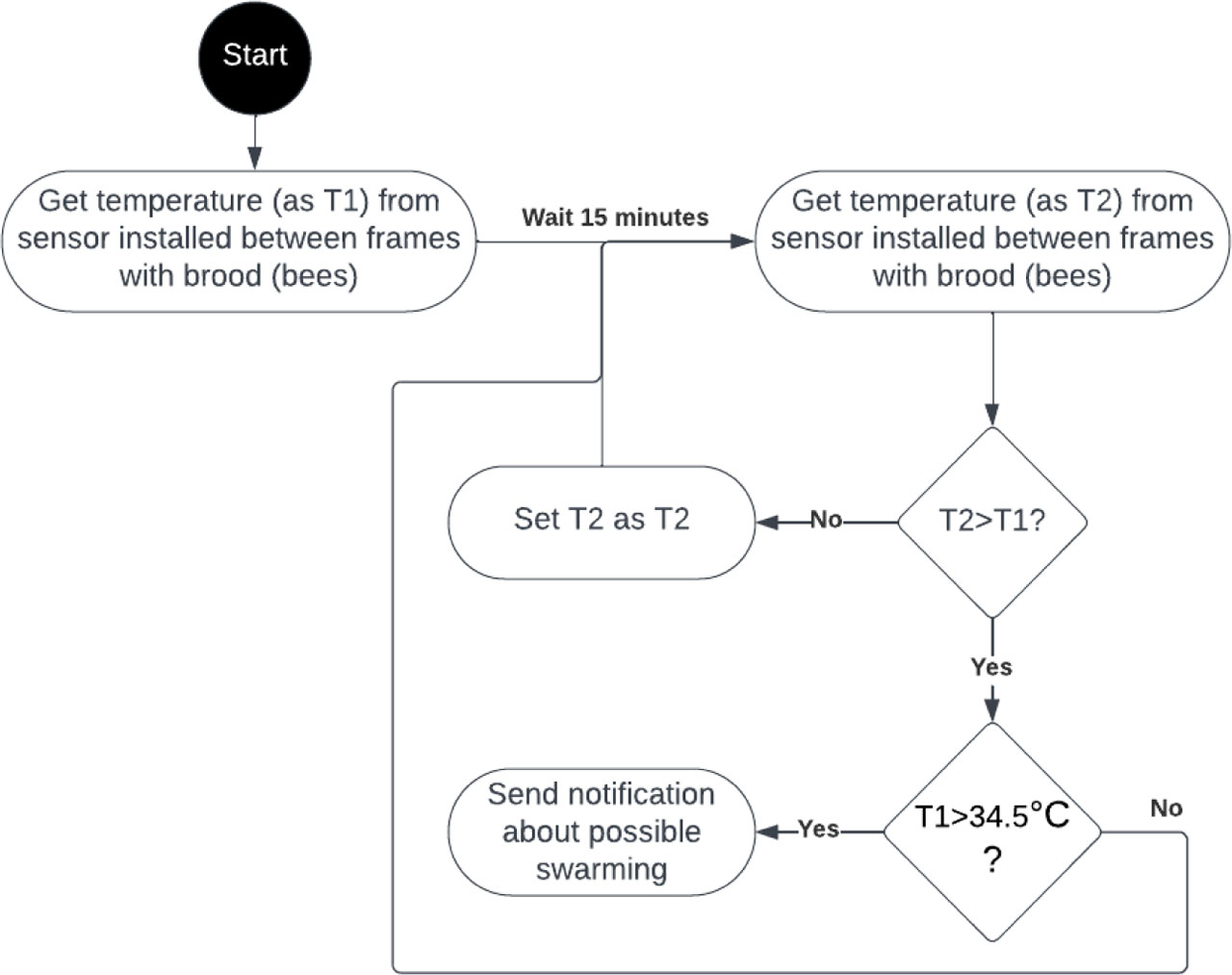
Fig. 13.
Diagram of how the algorithm for detecting diseases in bees works
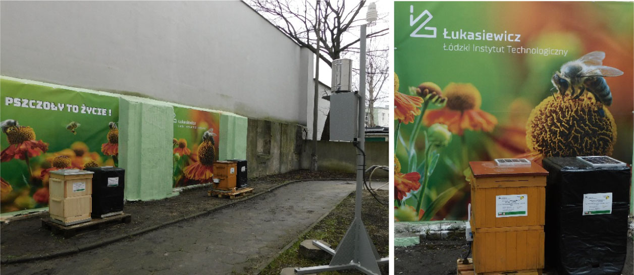
Fig. 14.
Experimental intelligent apiary