
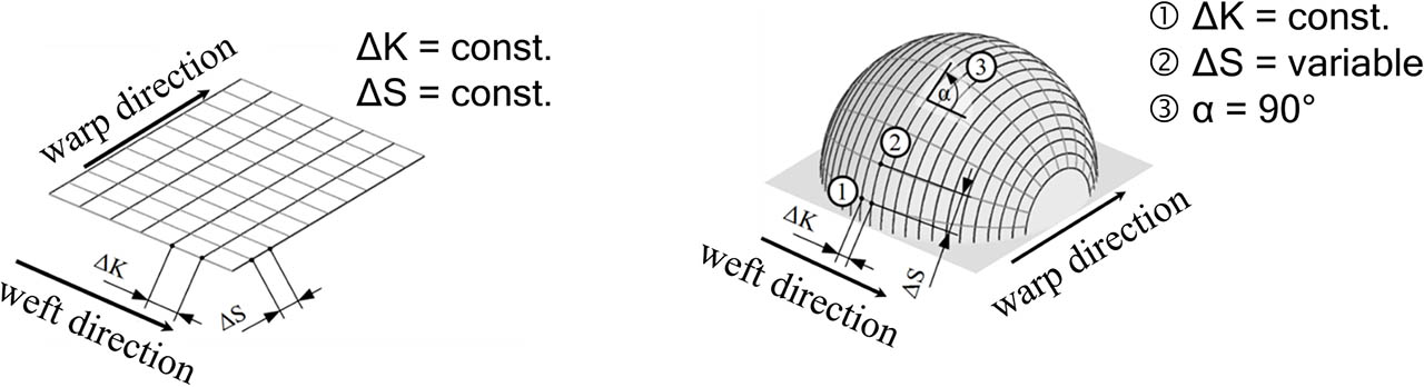
Fig. 1
Left: conventional scrim with constant yarn section lengths; right: scrim developed at ITM with variable warp yarn section lengths [11]
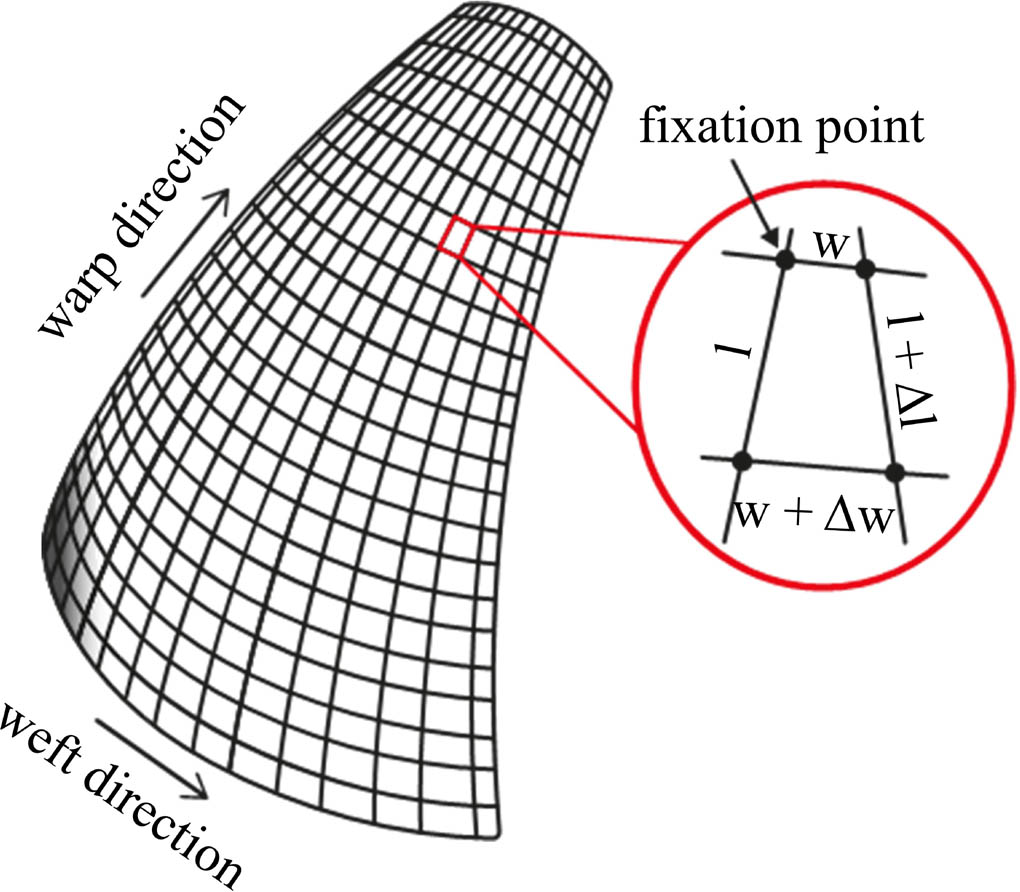
Fig. 2
Development goal: Distortion-free 3D geometry (exemplary shell segment for textile concrete applications), length (l), width (w)
Table 1
Materials used, basic textile machinery and restrictions
| position | 0° | 90° |
|---|---|---|
| manufacturer | Teijin Carbon Europe GmbH, Wuppertal (Germany) | |
| material | Carbonfilament yarn | |
| linear densitiy in tex | 800 – 3200 | |
| thread distance in mm | 30 | 35 |
| development aim | Modular retrofit on an existing multiaxial warp knitting machine (Karl Mayer Malimo 14024, working width 50″) | |
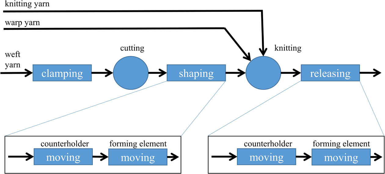
Fig. 3
Functional diagram of the weft reserve formation process for multiaxial warp knitting machines
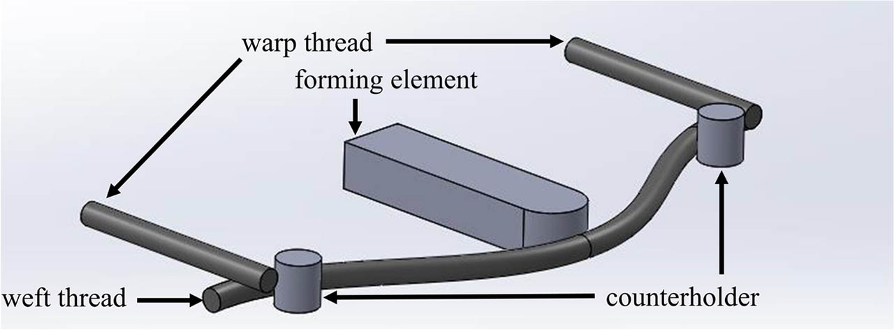
Fig. 4
Preferred concept for the design-technological implementation of the complete forming unit system for weft reserve formation

Fig. 5
Preliminary tests to investigate the demoulding behaviour of a carbon roving; marked in red: shaping direction (top view)
Table 2
Deformation of the carbon roving
| height in mm | width in mm | |
|---|---|---|
| carbon roving laid | 0.2 | 15.0 |
| carbon roving shaped | 5.1 | 2.4 |
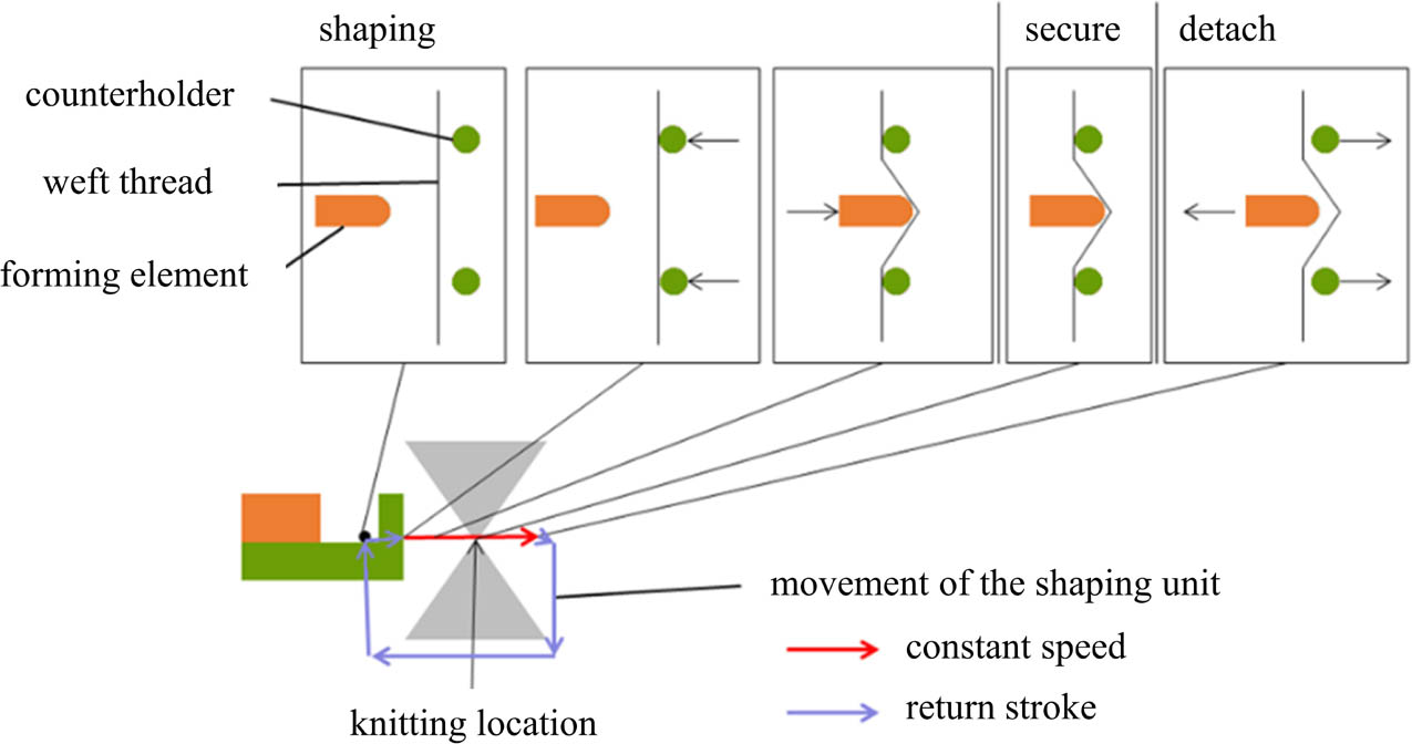
Fig. 6
Technology concept and motion path of the functional elements
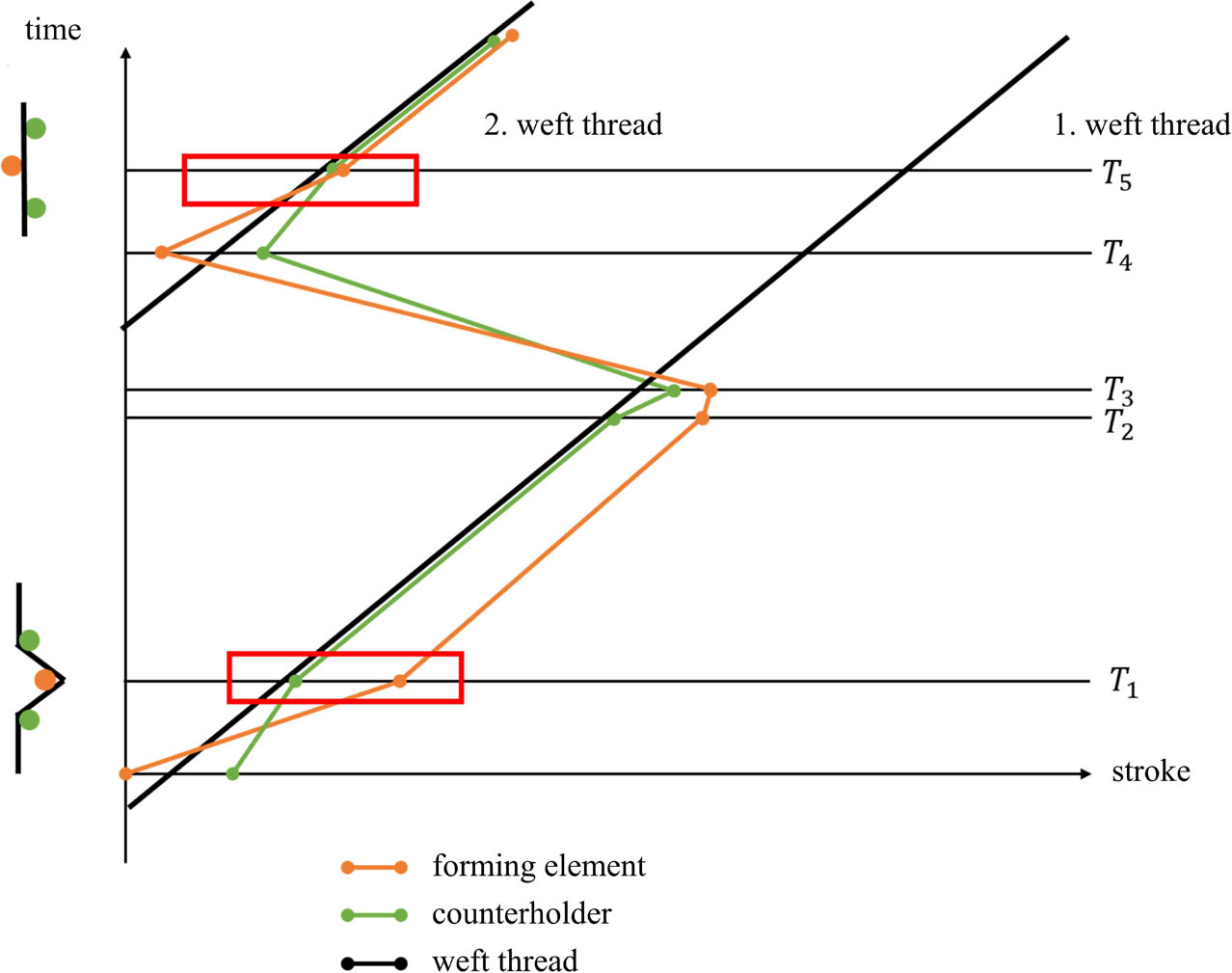
Fig. 7
Kinematic principle of operation of the weft reserve system
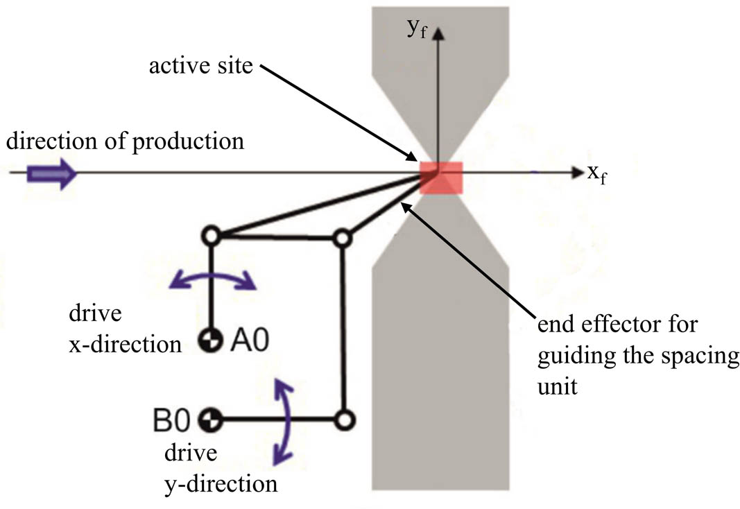
Fig. 8
Schematic diagram of the mechanism for moving the forming unit (A0, B0: pivot points of the drive)

Figure 9
Schematic diagram of the mechanism for moving the forming element within the movement of the demoulding unit
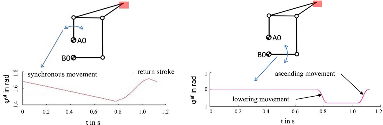
Fig. 10
Movement profile of the counterholder: in the production direction (xf) (left), and: in the yf direction (right)
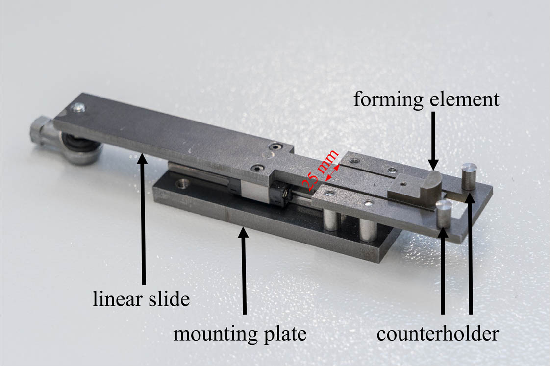
Fig. 11
Shaping unit developed for forming the weft reserves
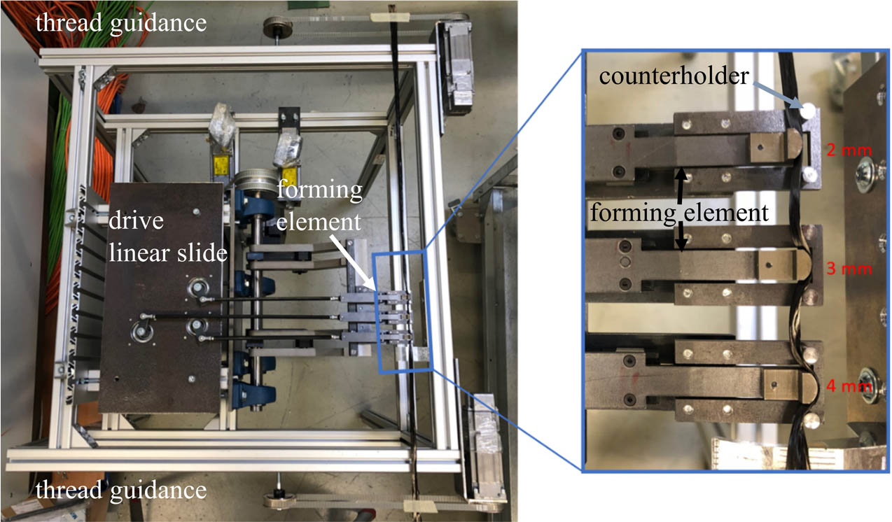
Fig. 12
Implemented test rig with exemplary representation of the (weft) yarn reserves realised

Fig. 13
Representation of the gearbox system of the test rig developed for forming a weft reserve (side view)
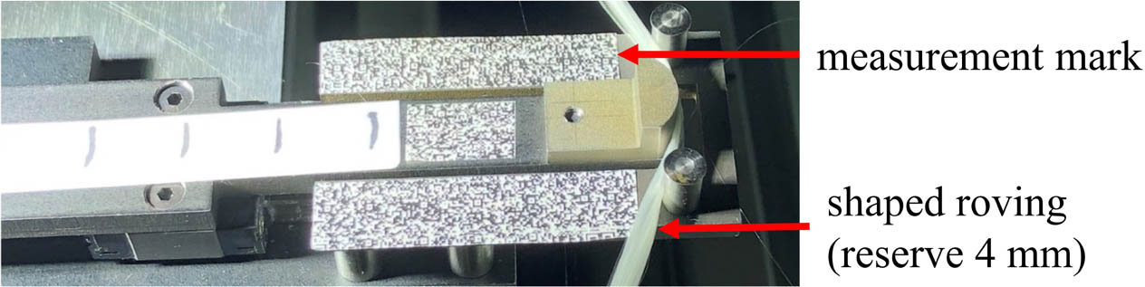
Fig. 14
Spacing of a glass thread (linear density 1200 tex)
Tab. 3
Comparison of speeds theoretically determined and measured using a representative measurement point to identify TARGET/ACTUAL deviations as a function of the engine speed
| Point | Engine speed in m−1 | Velocity (measured) in mm/s | Velocity (theoretically) in mm/s | Deviation in mm/s | Percentage of deviation |
|---|---|---|---|---|---|
| 1 | 24 | collision | 637.60 | - | - |
| 12 | 244.90 | 215.41 | 29.49 | 12.04 | |
| 6 | 122.20 | 107,70 | 14.50 | 11.87 | |
| 2 | 24 | collision | 65.43 | - | - |
| 12 | 23.99 | 22.10 | 1.89 | 7.88 | |
| 6 | 11.34 | 11.05 | 0.29 | 2.56 | |
| 3 | 24 | collision | 26.67 | - | - |
| 12 | 9.25 | 9.01 | 0.24 | 2.59 | |
| 6 | 4.60 | 4.51 | 0.09 | 1.96 |