

1. Introduction
Due to the rapid advancements in construction techniques, small-scale fibers such as steel, glass, carbon, and synthetic polymers like polypropylene are increasingly incorporated to enhance concrete performance. By tailoring their aspect ratio (L/d), geometry, shape, and surface roughness, these fibers significantly improve the resistance of structural elements against many mechanisms of failure (Abbass et al., 2019; Amin & Bentz, 2018; Hilles & Ziara, 2019; McMahon & Birely, 2018; Meda et al., 2005; Qi et al., 2018; Shahnewaz & Alam, 2014). Steel fiber (SF), for instance, has been used in the past four decades for improving the overall behavior of reinforced concrete (RC) members. Such fibers can act as a bridge to transfer the tensile forces across the cracks and resulting in reducing the width of cracks and therefore enhances the ductility of the concrete in comparison with elements without SF (Mashrei, 2018). Indeed, such improvement, depends on the properties, dosage and distribution of the fibers, as well as the properties of the concrete.
Conventional RC beams are normally reinforced with vertical stirrups shear reinforcement to prevent failure due to shear stresses. The addition of steel fibers to concrete with an aspect ratio ranging between 20 to 100 would further improve the shear strength and reduce the width of cracks (Al-Ta’an & Al-Feel, 1990; Bentur & Mindess, 2019). Additionally, steel fiber can be used as an alternative to conventional steel reinforcement in structural elements. For instance, ACI 318-25 (ACI Committee 318, 2025), allows the use of deformed steel fibers conformed to ASTM A820 (A01 Committee, 2022) with aspect ratio ranging between 50 to 100 as an alternative to minimum shear reinforcement. In general, among the main advantages of using steel fiber over traditional shear reinforcement is that it can be entirely distributed throughout the concrete mix with small spacing compared to shear reinforcement, and therefore, can “bridge” or postpone the growth of all kinds of cracks. Although other materials and techniques such as ferrocement jacketing (Al-Rawe et al., 2024, 2026) or Externally Bonded Fiber Reinforced Polymers (EBFRP) (ACI PRC-440.2, 2023; Manos et al., 2011; Mostofinejad & Tabatabaei Kashani, 2013) have proved their effectiveness, the ease of incorporating steel fiber into the concrete mix, compared with such techniques or conventional steel reinforcement, makes it particularly desirable for such applications, especially in shallow beams where placing vertical stirrups is difficult.
Considering the importance of such materials, several experimental studies have been recently conducted to investigate the shear strength of steel-fiber reinforced concrete (SFRC) beams (Sahoo et al., 2016; Chalioris & Sfiri, 2011; Mohammad Reza Zarrinpour and Shih-Ho Chao, 2017; Kyoung-Kyu Choi, Hong-Gun Park, and James K. Wight, 2007). In addition, numerous theoretical works have been conducted using various analytical methods such as finite element analysis and empirically-derived equations (Adhikary & Mutsuyoshi, 2006; Yoon-Keun Kwak, Marc O. Eberhard, Woo-Suk Kim, and Jubum Kim, 2002) to estimate the shear strength of SFRC beams.
Extensive scientific research has been conducted to evaluate the mechanical behavior and structural performance of concrete reinforced with single-type steel fibers, primarily comparative studies testing either hooked-ends or crimped fiber geometries in isolation (Khalaf et al., 2024; Ouda & Mashrei, 2022; Wang et al., 2023). While hooked-ends fibers are widely investigated for their distinct mechanical end-anchorage and crimped fibers for their continuous wave-like mechanical interlock along the fiber length, existing structural studies predominantly evaluate these shapes separately or combine steel fibers with synthetic polymers like polypropylene (Duhaim & Mashrei, 2024; Haider et al., 2024; Kachouh et al., 2021). Consequently, direct experimental research investigating a dual blend of both hooked-ends and crimped steel fibers within the exact same concrete matrix remains remarkably scarce in the literature, presenting a distinct research gap regarding their combined multi-geometrical synergy on shear transfer, crack propagation control, and post-cracking ductility.
Furthermore, while shear transfer mechanisms in standard beams (a/d > 2.5) have received considerable attention, the performance of deep beams, where structural behavior is dominated by arch action and complex diagonal compression struts rather than conventional shear mechanisms (Alizadeh et al., 2023), remains largely unexplored, especially when with dual-geometry steel fiber is implemented as main shear reinforcement. To address this critical research gap, the current study experimentally investigates the shear strength, diagonal cracking behavior, and post-cracking load-carrying capacity of concrete deep beams reinforced with a single and dual blend of hooked-end and crimped steel fibers
2. Experimental Program
This section describes the details of beam specimens, their construction steps, the properties of the materials used, the instrumentation utilized and testing procedures.
2.1. Beam Specimens
In order to achieve the objectives of the research, eleven simply supported beams were evaluated. All beams were cast with constant cross-section of 200 mm in depth and 120 mm in width. The beam specimens had a constant shear span - to - effective depth ratio (a/d) which is 2. All beams were reinforced with 2Φ10 mm and 1Φ12 mm bars as flexural reinforcement, placed along the beam soft. Approximately, 25 mm concrete clear cover was maintained around the section of the beam. The beams were tested under four-points loading scheme up to failure. The geometry and testing setup of tested beams are shown in Fig. 1. Two control specimens were evaluated in this research; one (B_0) has been left without any kind of shear reinforcement and the other (BS_0) has been reinforced by using Φ6 mm steel links placed at a spacing of 60 mm throughout the shear spans and 100 mm throughout the middle third of the beam. This quantity of shear reinforcement is more than the minimum reinforcement calculated according to ACI 318-25 specification by approximately 10%. The remaining beams have been divided into three groups of three specimens each. The specimens of the first group were reinforced with hooked-ends steel fibers as shear reinforcement with three volume fractions (Vf) of 0.7%, 1.05%, and 1.4%. The second group is similar to the first one, except that crimped steel fiber has been implemented instead of hooked-ends fiber. Mixed (hooked-ends and crimped) fibers of the same percentages have been utilized in the third group. Each specimen has been reinforced against shear stress by 0.7%, 1.05% or 1.4% of the concrete weight. Details of all beam specimens are listed in Table 1.
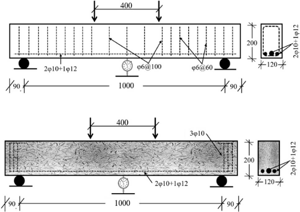
Figure 1:
Test configurations and details of the tested beams (above) beam BS_0; (bottom) beams with SF
Table 1:
Details of beam specimens tested
| No. | Specimen designation* | Steel Fiber Type** | Vf [%] | Shear Reinforcement [Stirrups] | Average Measured fcu [MPa] |
|---|---|---|---|---|---|
| 1 | B_0 | --- | 0 | --- | 43.0 |
| 2 | BS_0 | --- | 0 | See Fig. 1 | 44.8 |
| 3 | BH_0.7 | H | 0.7 | --- | 46.0 |
| 4 | BH_1.05 | H | 1.05 | --- | 51.0 |
| 5 | BH_1.4 | H | 1.4 | --- | 50.5 |
| 6 | BC_0.7 | C | 0.7 | --- | 48.5 |
| 7 | BC_1.05 | C | 1.05 | --- | 52.0 |
| 8 | BC_1.4 | C | 1.4 | --- | 50.0 |
| 9 | BM_0.7 | M | 0.7 | --- | 46.5 |
| 10 | BM_1.05 | M | 1.05 | --- | 49.0 |
| 11 | BM_1.4 | M | 1.4 | --- | 48.0 |
2.2. Materials and Procedures
The materials used in this study include crimped and hooked steel fibers, steel rebar, 19 mm maximum size coarse aggregate, fine aggregates, cement and superplasticizer. The control concrete mix was designed to achieve a target cube compressive strength of 45 MPa tested according to BS EN 12390 (European Committee for Standardization, 2019). Three concrete cube specimens of 150 mm ×150 mm ×150 mm for each beam were cast, cured in water basin for 28 days, and then tested. The cement and fine aggregate conformed to ASTM C150 (ASTM International, 2015b) and ASTM C33 (ASTM International, 2013) standards, respectively. The steel rebar was tested and conformed to ASTM A615 (ASTM International, 2009). High-range water reducer (Conplast SP2000) conformed to ASTM C494 (ASTM International, 2015a) was used in this study to control the loss of workability due to the presence of steel fiber. Hooked and crimped steel fibers have been used throughout this study. The material properties of steel fibers and water reducer were obtained directly from the manufacturer. A summary of material properties is shown in Table 2.
Table 2:
Properties of the Materials Used
| Material | Property | Value | |
|---|---|---|---|
| Steel | Yield strength [MPa] | 520 | |
| Ultimate strength [MPa] | 690 | ||
| Elongation [%] | 12 | ||
| Conplast SP2000 | 1.22 at 25°C | Specific gravity | |
| Brown liquid | Appearance | ||
| Steel Fibers | Type | Hooked-ends | Crimped |
| Length [mm] | 50 | 50 | |
| Diameter [mm] | 1 | 1 | |
| Aspect Ratio | 50 | 50 | |
| Tensile Strength [MPa] | 1000 | 1100 | |
Reinforcement cages were constructed at the Civil Engineering Department of the University of ThiQar. Formwork were made from plywood board and they had been oiled prior to the placement of the reinforcement cages. It should be noted that the longitudinal reinforcements of Φ10 mm were hooked upwards behind the supports and enclosed by additional two Φ10 mm bars as stirrups at each end to prevent the possibility of failure at supports. Figure 2 shows examples of reinforcement cages
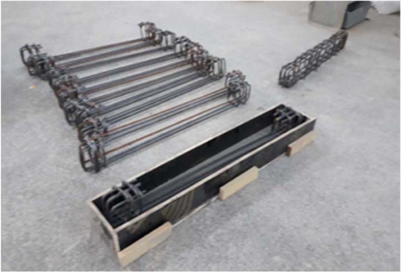
Figure 2:
Reinforcement cages and beams formwork
2.3. Mixing, Casting and Curing
Table 3 shows the mix proportions for both mixes with and without steel fiber. The control concrete mix was designed to achieve a target cube compressive strength of 45 MPa tested according to BS EN 12390 (European Committee for Standardization, 2019). As stated previously, each beam was cast with three concrete cube specimens of 150 mm ×150 mm ×150 mm to estimate the concrete compressive strength (fcu). Curing and storage of the test cubes were kept identical to the conditions of the test beams. All specimens, beams and concrete cubes were covered with wet material and plastic sheets on top to prevent moisture loss. The beams were kept moist at all times during the curing period, which lasted 3 days. The formwork was stripped at the end of the third day, and the beams were stored in the laboratory until tests. Figure 3 shows the types of steel fibers used and specimens’ preparation.
2.4. Test Setup and Instrumentations
As schematically shown in Figure 1 above, the beam specimens were tested under four-points loading configuration up to the failure state is reached. All beams were painted by white-color painting liquid prior to testing to facilitate the crack propagation monitoring. The load was applied with a constant rate by a testing machine of 2000 kN maximum capacity. The mid-span deflection was measured using a high-accuracy dial gauge located at the mid-span of the beam. During the tests, the applied load, and deflection were recorded and the propagation of cracks was monitored from both sides of the tested beams.
Table 3:
Concrete Mix Proportions
| Proportion by Weight [Kg/m3] | ||||||
|---|---|---|---|---|---|---|
| Mix Type | Cement | Fine Aggregate | Coarse Aggregate | Water | Steel Fiber (SF) | Conplast SP2000 |
| Mix without SF | 400 | 775 | 1030 | 176 | 0 | 5.2 |
| Mix with SF | 400 | 775 | 1030 | 176 | 49, 73.5 or 98 | 5.2 |
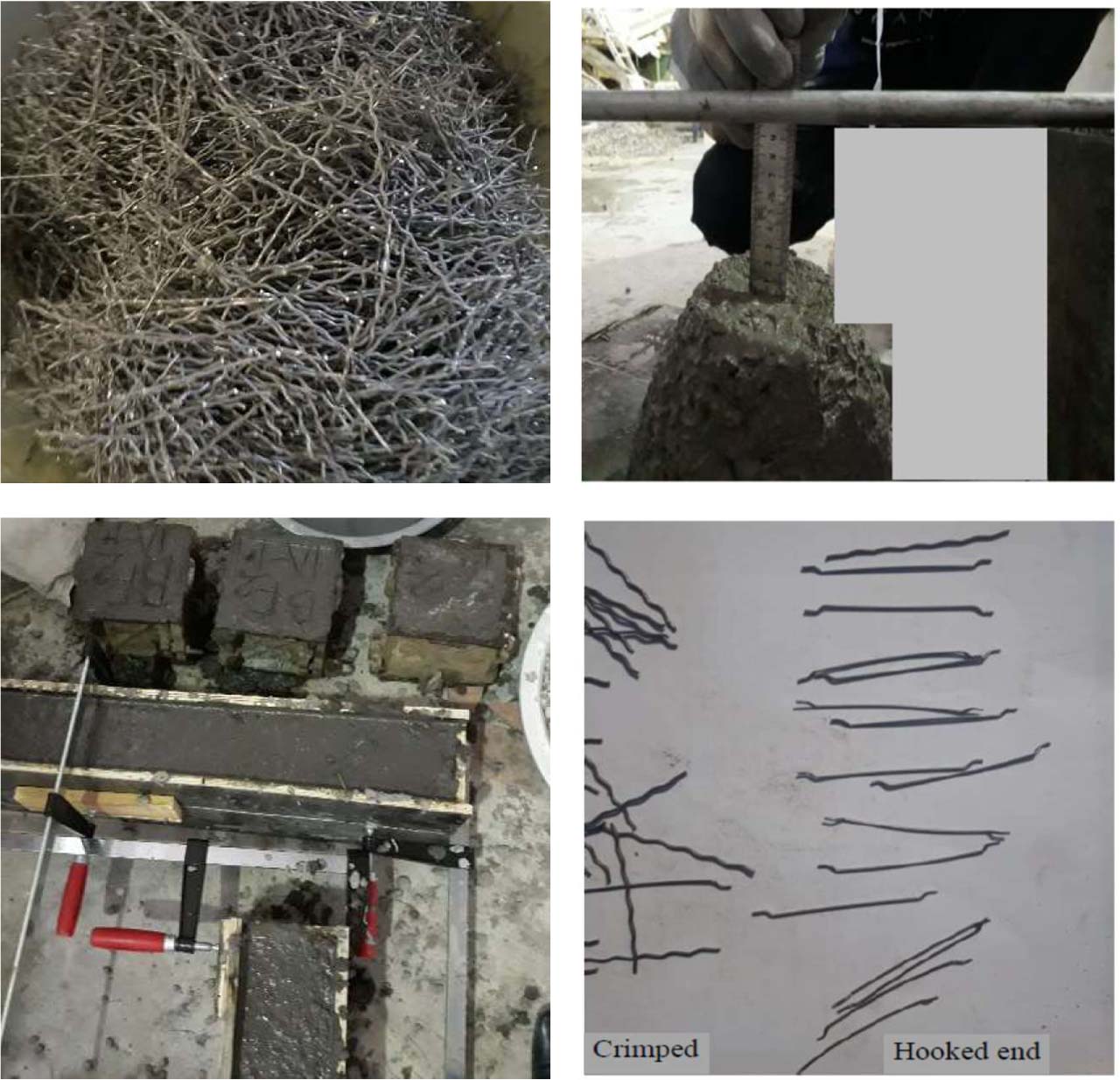
Figure 3:
Types of the steel fibers used and casting of specimens
3. Results
Four-point bending test has been performed on RC and SFRC beams using three different types of steel fibers (hooked-ends, crimped, and dual-geometry mix of both fiber types) with three percentages of volume fraction (0.7%, 1.05%, and 1.4%) of steel fibers in addition to two beams without steel fibers. The experimental results of the eleven tested beams including the maximum applied load, mid-span deflection, and mode of failure are evaluated and summarized in Table 4. In general, it has been determined that increasing the fiber volume fraction up to 1.05% has provided the optimum results in terms of load-carrying capacity and deflections. In addition, incorporating a dual-geometry fiber by 50/50 mixing both types of fibers has outperformed the behavior of either individual fiber studied. The load-deflection behavior of the tested beams, in addition to the effect of fiber volume fraction and type will be extensively discussed in the following section.
Table 4:
Experimental Results of the Tested Beams
| No. | Specimen | Pu [kN] | Pu [%] Compared to B_0 | Pu [%] Compared to BS_0 | Max Deflection [mm] | Mode of Failure |
|---|---|---|---|---|---|---|
| 1 | B_0 | 76.0 | 100 | −33 | 4.2 | Shear failure |
| 2 | BS_0 | 114.0 | 150 | 100 | 6.86 | Shear failure |
| 3 | BH_0.7 | 126.0 | 165 | 110.5 | 7.92 | Shear failure |
| 4 | BH_1.05 | 143.2 | 188 | 125.4 | 13.68 | Shear-Flexure failure |
| 5 | BH_1.4 | 151.0 | 199 | 132.4 | 11.7 | Flexure failure |
| 6 | BC_0.7 | 119.6 | 157 | 105 | 9.88 | Shear failure |
| 7 | BC_1.05 | 134.0 | 176 | 117.5 | 10.58 | Shear-Flexure failure |
| 8 | BC_1.4 | 142.0 | 187 | 124.5 | 11.46 | Flexure failure |
| 9 | BM_0.7 | 152.0 | 200 | 133.3 | 15.65 | Shear-Flexure failure |
| 10 | BM_1.05 | 160.0 | 211 | 140.3 | 18.36 | Flexure failure |
| 11 | BM_1.4 | 155.0 | 204 | 136 | 15.02 | Flexure failure |
4. Discussion
4.1. Effect of Vf
Figures 4 to 6 and Table 4 show the results of maximum loads and corresponding deflections with variable volume fraction of SF from 0 to 0.7%, 1.05%, and 1.4%. It was observed that with an increase in steel fiber percentage, regardless of the type of steel fiber used, the shear strength and corresponding ductility (based on the ultimate recorded midspan deflection) have been significantly increased. This can be explained due to the contribution of steel fiber to “bridging” the developed cracks and therefore providing better ability to resist shear stresses (Le et al., 2019; Li et al., 1993). Notably, for the beams with mixed fibers (M-Series), the 1.05% SF volume fraction achieved better performance than the 1.4% dosage, indicating that peak shear enhancement does not necessarily require highest fiber content. This finding is practically advantageous, as a lower fiber dosage can significantly reduce mixing time and effort, improve fresh concrete workability, and indeed offer a more economical fiber-reinforcement solution without compromising structural performance.
The reduced performance at 1.4% SF relative to 1.05% is likely attributable to workability loss and increased fiber clustering at higher mixed fiber dosages, which can compromise uniform fiber distribution despite the higher nominal fiber content. This suggests that 1.05% represents a practical optimum, balancing shear performance gains against workability, mixing effort, and material cost. Generally, the load carrying capacity of the fiber-reinforced concrete beams, regardless of the fiber type, ranged from 165% to 211%, and from 105% to 140% of the load carrying capacity compared to beams B_0 and BS_0, respectively.
In addition, according to test results presented in Table 4 and Figures 4 to 6, it can be seen that the beams involved a small volume fraction of steel fiber (i.e., 0.7% in this study regardless of the type) have provided higher strengths than the beam constructed with minimum traditional reinforcement (BS_0). Therefore, it can be concluded that the steel fiber, especially the mixed fiber, can be successfully used to resist shear stresses in RC beams instead of stirrup with minimum (or even more quantity) according to ACI 318-25. It should be mentioned that the present results corroborate those obtained by (Zhi et al., 2025), where it has been reported that incorporating 1.0% hooked-end steel fiber improved the load-carrying capacity by 63% compared to normal concrete and such a steel fiber dosage can be equivalent to D8@200mm conventional stirrups.
Furthermore, Table 4 and Figures 4 to 6 clearly illustrate that the deflection at maximum load increases consistently with the percentage of steel fibers. This indeed, will result in a better ductility as compared to the beam reinforced with minimum traditional shear reinforcement as in beam BS_0. This dual-geometry approach offers a novel strategy for optimizing fiber-reinforced shear design in deep beams, particularly where enhanced ductility and crack control are needed without relying solely on conventional shear reinforcement.
4.2. Effect of Fiber Type
Table 4 and Figures 7 to 9 present the load carrying capacity and load-deflection relationships for beams reinforced with different types of steel fibers (hooked, crimped and mix of hooked and crimped). As was previously discussed, all beams have been constructed with identical longitudinal reinforcement ratio, fiber volume fraction, effective depth and shear span – to – depth (a/d) ratio. It can be noted that the beams constructed with hooked fibers (H-Series) exhibited 5.4%, 6.8% and 6.3% higher max load compared to those with crimped fibers (C-Series) for the volume fraction of 0.7%, 1.05%, and 1.4% respectively. Similarly, the beams constructed with a mixed steel fiber (M-Series) exhibited 27%, 19.5%, and 9% higher max load compared to those with crimped fibers for a volume fraction of 0.7%, 1.05%, and 1.4%, respectively. It should be mentioned that the beams reinforced with mixed type presented higher max load as well as higher deflection at the maximum load with respect to hooked and crimped fibers. This may be attributed to the enhanced bond provided by the mixed fibers type.
Figure 10, on the other hand, illustrates the effect of steel fiber (SF) volume fraction on the shear strength of the beams with the three types of fibers tested. All three fiber types exhibited roughly a similar trend, with shear strength increasing sharply between 0% and 0.7% SF volume fraction, followed by a more gradual increase up to 1.4%. It has been noted also that as the volume fraction increases, the mixed-fiber specimens consistently outperform the single-fiber types, reaching a peak shear strength of about 80 kN at a volume fraction of approximately 1.05%, before slightly declining to around 77.5 kN at 1.4%. This suggests that combining fiber geometries produces a synergistic effect on crack-bridging and shear resistance, though a slight reduction beyond the optimum fraction (∼1.05%) may indicate diminishing returns from fiber balling or reduced workability at higher dosages.
The hooked-end fiber specimens showed the second-highest performance, achieving roughly 75.5 kN at 1.4% volume fraction, while the crimped fiber specimens exhibit the lowest shear strength gain, reaching about 71 kN at the same fraction. The consistently lower performance of crimped fibers compared to hooked-end fibers can likely be attributed to differences in mechanical anchorage; hooked-end fibers typically provide superior pullout resistance due to their end-hook geometry compared to the wave-like deformation of crimped fibers (Abdallah & Rees, 2019; Zīle & Zīle, 2013).
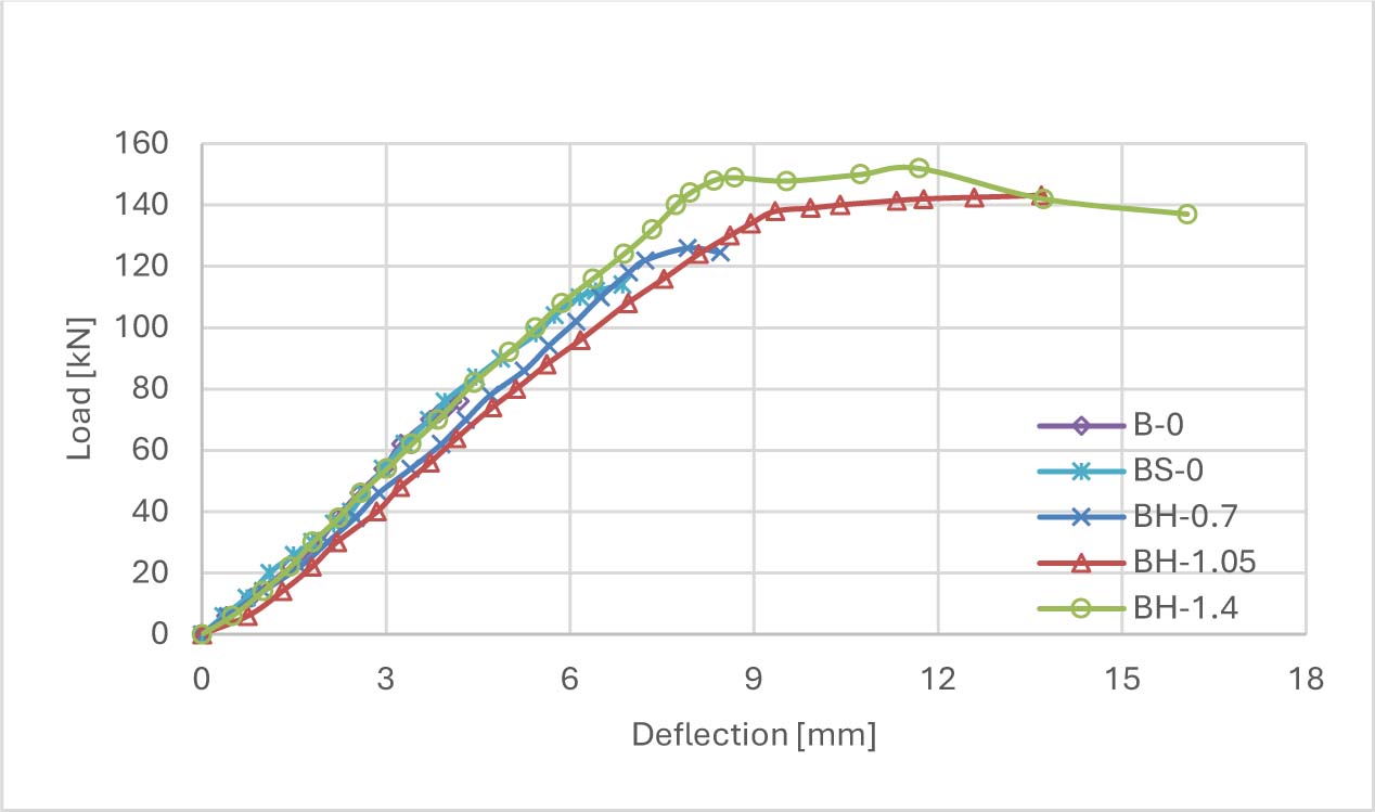
Figure 4:
Load - Midspan deflection for beams reinforced with hooked-ends steel fibers
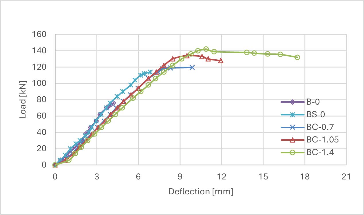
Figure 5:
Load - Midspan deflection for beams reinforced with crimped steel fibers
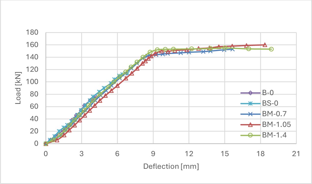
Figure 6:
Load - Midspan deflection for beams reinforced with mixed steel fibers
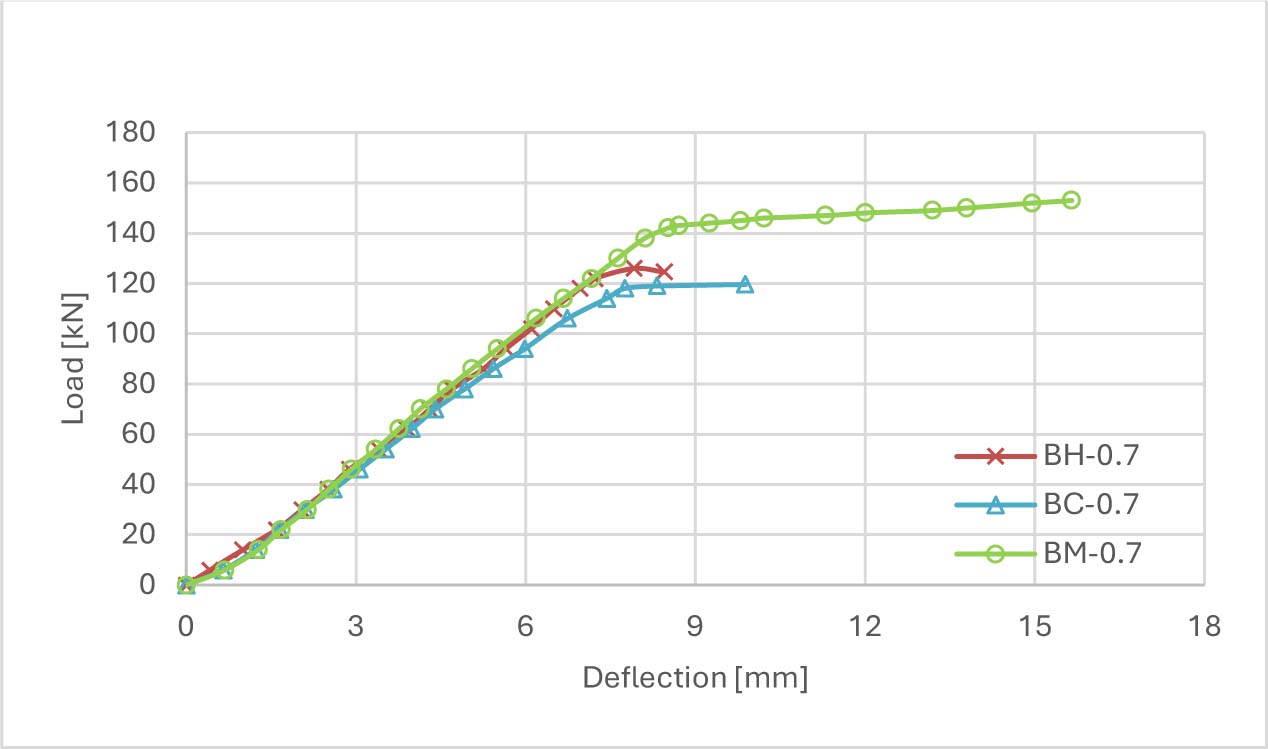
Figure 7:
Load - Midspan deflection for beams reinforced with 0.7% steel fibers
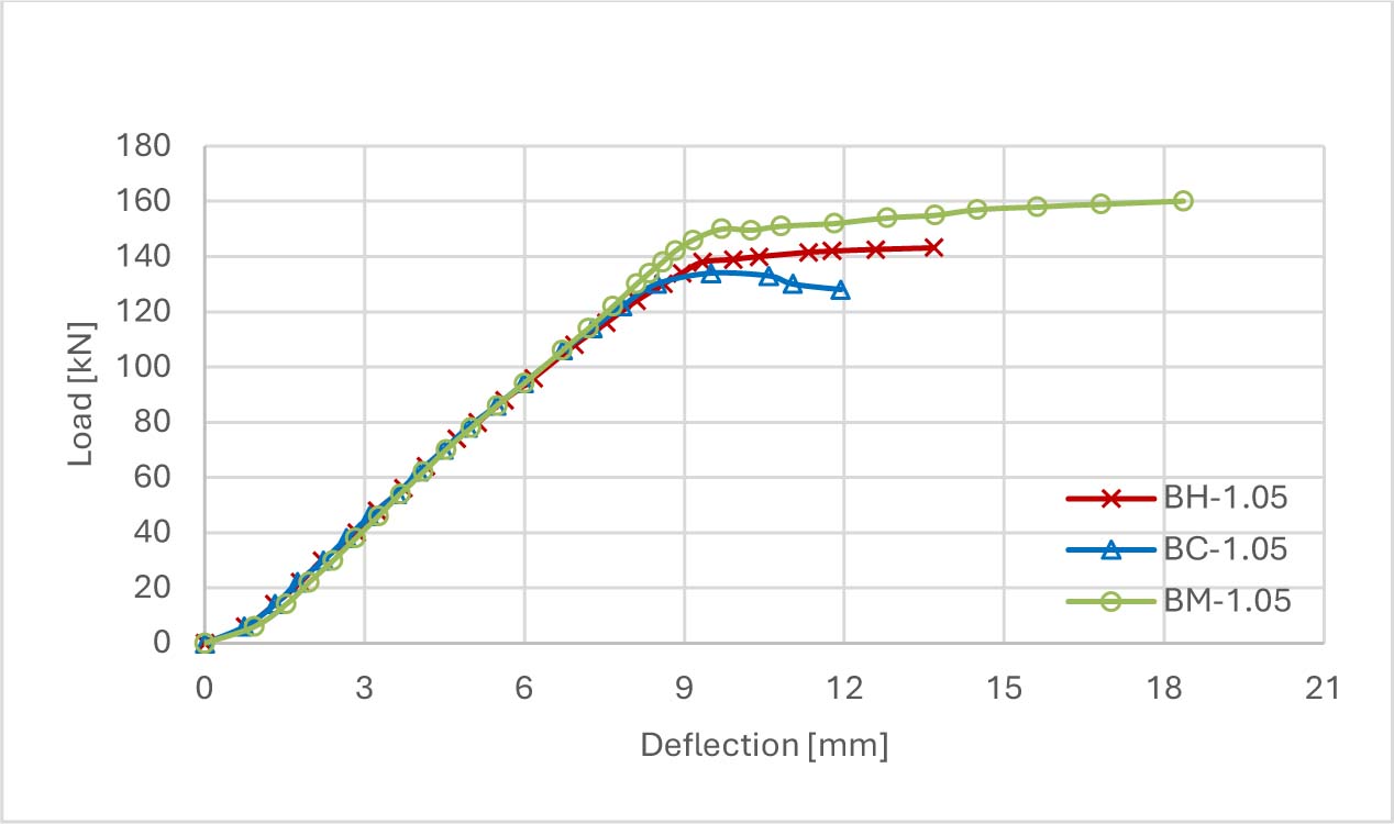
Figure 8:
Load - Midspan deflection for beams reinforced with 1.05% steel fibers
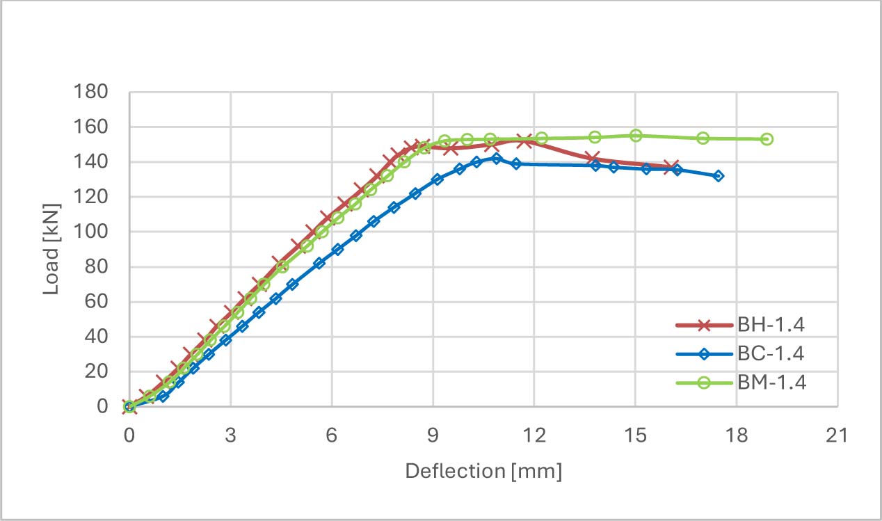
Figure 9:
Load - Midspan deflection for beams reinforced with 1.4% steel fibers
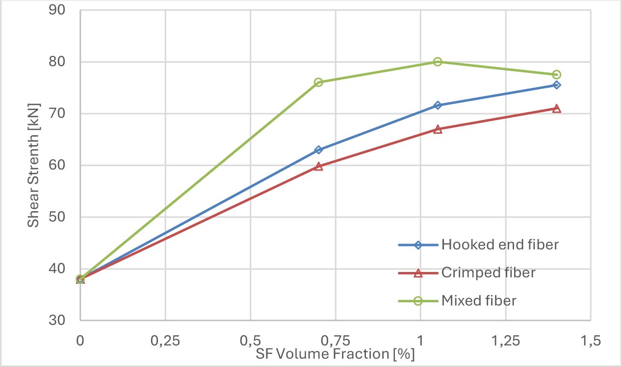
Figure 10:
Effect of volume fraction of steel fiber on shear strength
4.3. Failure Mode and Crack Patterns
The last column in Table 4 summarizes the failure modes of the beams tested in this research. In general, three distinct failure modes were observed in this experiment, namely, a pure shear failure by diagonal shear cracks, a combination of flexure and shear failure, and a pure flexural failure.
In beam B_0, which has no steel fiber, few and small flexural cracks first observed in the middle third region of the beam and followed by one major shear crack formed between the applied load and nearest support; within the regions of constant shear. Finally, the beam failed abruptly by a diagonal shear crack. The same behavior was approximately demonstrated by beam BS_0, which had been strengthened by means of conventional shear reinforcement, but with larger load carrying capacity as compared to beam B_0.
The incorporation of steel fiber showed a significant effect on the crack patterns, where clear differences in the crack intensity and distribution of the steel fibrous beams were observed. Regardless of the type of steel investigated, as the steel fiber percentage increased from zero to 1.4%, the failure mode changed from pure diagonal shear failure at low dosage of SF to a pure flexural failure at higher SF content, passing through shear-flexural failure at intermediate (i.e., 1.05%) SF content. Rather than a single major crack, the transition from pure shear to pure flexural failures was accompanied by developing extensive small cracks distributed at constant shear and constant moment regions along the span of the tested beams. This transition, in addition, indicates the effectiveness of the steel fiber incorporation for the shear strengthening applications where the failure has been changed from sudden to a more gradual failure due to the improved ductility of the tested beams with SF. This behavior was observed in all tested groups. For instance, Figure 11 shows the crack patterns of beams B_0, BS_0, BH_1.05, BC_1.05 and BM_1.05.
Similarly, the failure modes of beams BM_0.7, BM_1.05 and BM_1.4 reinforced with mix of steel fibers were combination of shear and flexure failure for beam BM_0.7 and pure flexural failure for both beams BM_1.05 and BM_1.4. This indicates the extraordinary performance of mixed steel fiber as compared to a single-type fiber at each fiber content percentage.
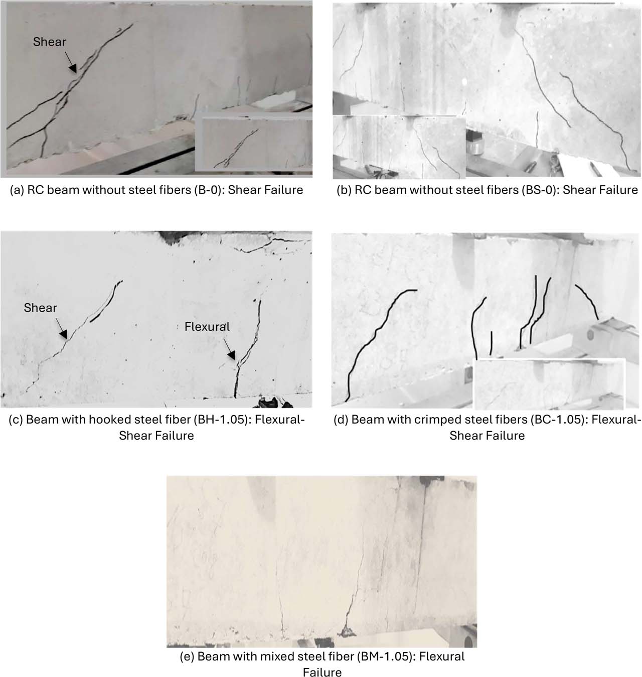
Figure 11:
Modes of failures and cracks patterns of some tested beams
5. Conclusions
This experimental work investigated the shear performance of hooked-ends, crimped and mixed steel fibers. Based on the results obtained and the graphs constructed, the following conclusions are reached:
Overall, the results demonstrate that steel fibers significantly enhance both the compressive and shear strengths of the SFRC beams. Notably, the cube compressive strength (fcu) reached its peak at a steel fiber content of 1.05%.
Compared to the control beam, the increase in the shear strength ranged from 57% to 100% for beams with 0.7% SF volume fraction.
Compared to the control beam, the increase in the shear strength ranged from 76% to 111% for beams with 1.05% SF volume fraction, and from 87% to 104% for beams with the 1.4% SF volume fraction.
Compared to the control beam with stirrup reinforcement, the increases in beam strength ranged from 11% to 40% for beams with 0.7% SF volume fraction.
The failure mode of beams reinforced with crimped or hooked steel fibers with the volume fraction of 0.7% was a shear failure while the beam reinforced with mixed fibers (hooked and crimped) failed by flexure-shear failure. This indicates a better performance of mixed fiber in resisting shear stresses as compared to a single-type steel fiber.
The failure mode of RC beams reinforced with crimped or hooked steel fibers with the volume fraction of 1.05% and 1.4% were flexure-shear failure and flexure failure respectively, while the beam reinforced with mixed fibers (hooked and crimped) failed by flexure failure for both volume fraction 1.05% and 1.4%.
The addition of steel fibers consistently increased the deformation capacity and decreased the crack sizes. This increased deformation can result in greater ductility, which is desirable property for the structural elements especially in seismic loading.
Acknowledgements
The authors gratefully acknowledge the College of Engineering, University of ThiQar, for granting access to its instruments, which enabled the experimental component of this research.
Notes
[4] Contributed by Author Contributions
Both the first and second authors, A. M. M. & M. A. M. conceived and designed the study, conducted the experimental work and collected the data. The third author, A. A. S. performed the statistical analysis and contributed to data interpretation and manuscript drafting. All authors critically reviewed and approved the final version of the manuscript and agreed to be accountable for all aspects of the work.