

1. Introduction
One of the main load-bearing structural components of the building is the RC columns (ALOBAIDI et al., 2025). Due to deficiencies in materials, defects in design, inadequate construction, as well as quality control, larger loads, physical and chemical effects, steel reinforcement corrosion, fire hazards, and inadequate maintenance (Ezz-Eldeen H., 2011). Therefore, these columns may eventually need to be strengthened or repaired to ensure their safety, because their collapse means the collapse of the whole structure (DEWI et al., 2024).
The bending moment of RC slender columns under eccentric load is increased by the secondary moment because of their small cross-section in relation to their height. This increases the column’s susceptibility to lateral deflection, which affects its load-bearing capacity (Mohammed Za. et al., 2024). Historically, research on slender RC columns has concentrated on how well they function with respect to variables like cross-sectional dimensions and slenderness ratios, etc. (BAZANT et al., 1994; HYO-G & JI-HYUN, 2010; CHUANG & KONG, 1995; AL-Najafi, 2016; Al-Sarraf et al., 2009).
Recently, there has been much research on strengthening RC slender columns. A common technique for strengthening columns is the steel jacket method, especially for the non-ductile ones. This technology has numerous advantages, including reduced thickness relative to concrete jacketing, lighter weight, enhanced column confinement and bearing ability, improved shear strength and lateral load strength, improved ductility and stiffness, and reduced deflection (Abdel-Hay & Fawzy, 2015). The researchers investigated a number of factors, including the bonding technique and the strengthening material’s size, shape, thickness, as well as length, in order to strengthen columns by steel jackets.
Multiple studies, such as “Dolce et al. 2003; Adam et al. 2009; Montuori and Piluso 2009; Campione 2013; Makki and Nimnim 2015” investigated how steel angles and battens affected the short columns’ structural stability. The ultimate load was shown to rise with larger angles and batten sizes. Ezz-Eldeen H., (2016) used various sizes and numbers of angles and steel plates as horizontal and longitudinal straps to strengthen RC short columns and tested under eccentricity. The results indicated that the bearing capacity of the strengthened columns improved with larger angles and an increased surface area of the steel jackets due to the longitudinal steel dimensions. Additionally, increasing the number of horizontal straps delayed the buckling of the steel angles. Nimnim & Al-Bahadli, (2018) examined the effects of different concrete compressive strengths (normal and high), batten spacing, and reinforcement ratios on RC slender columns under different eccentricities by experimentation and analysis. Reducing eccentricity and batten spacing enhanced the maximum load-bearing ability of strengthened columns (high-strength concrete). Furthermore, the strengthening causes the mode of failure to change from local longitudinal steel bar buckling and sudden concrete crushing to slow spalling of the covering of concrete. They developed new analytical equations and observed that the discrepancy in maximum load between the suggested equations and experimental results from this work and other investigations ranged from 0.3% to 24.9%, with a mean of 7.05%. Eldeen et al. (2021) included a thorough evaluation of both experimental and analytical investigations regarding strengthening methods for reinforced concrete short columns utilizing steel jackets. They studied the effects of many variables such as compressive strength of concrete, strip thickness, dimensions, spacing, and angle size on loading capacity, ductility, lateral strength, and flexural strength of columns. The findings of these studies showed that the overall improvement in strength varied between 18.65% and 109%, and the lateral strength showed an improvement from 63% to 68%. Yansiku et al. (2022) propose an outer confinement to strengthen slender circular RC columns with steel straps and provide initial clamping force to the steel sheets. The steel straps are connected by bolts that generate varying initial clamping pressures. The suggested strengthening mechanism, including modifications of geometric modifications and stress, will improve the ductility of slender circular reinforced concrete columns that are subjected to lateral and vertical loads. The developed analytical model precisely predicted the performance of the suggested clamping mechanism for practical use. Abdelraheem et al. (2023) introduced an experimental study of rectangular RC columns strengthened with four steel angles and steel battens under axial load and studied the effect of the aspect ratio (from the cross-section’s longer to shorter side) and the size and spacing of the steel battens. This enhanced the load-bearing capability of the RC. The enhancement can be attributed to the constraining influence of the steel jacketing and the ability of the steel angles to bear an important portion of the applied axial load. The predominant cause of failure in most of the strengthened samples was the buckling of the steel angles. Salman and Salman & Al-Sherrawi, (2024) introduced a new analytical model based on the distribution method for plastic stress, which was proposed for creating a load-moment interaction diagram regarding a strengthened RC column using steel battens and C-section jacketing. The results indicated that this method for strengthening effectively improved the load as well as bending moment capacities of the columns. Amin et al. (2026) tested thirteen reinforced concrete columns during the experimental program. One specimen served as a control, while the remaining twelve underwent strengthening. These specimens varied in stirrup spacing, reinforcing materials such as glass fiber and steel rebar, and different concrete compressive strengths. The results revealed that the load-increasing ratio values increased from 2.87 to 4.13 times the reference specimen. The failure pattern was changed from brittle failure to ductile failure. Both stress-strain behaviour and axial load deformation were enhanced. The ductility was increased from twice to six times the value of the reference specimen. On the other hand, the designed proposal was compared with standard codes (ECP 203-2020 and Eurocode 4). Strengthening RC columns using steel jackets and filling with various concrete compressive strengths enhanced their durability, stiffness, and performance under eccentric loads.
A comprehensive review of the existing literature reveals that while the strengthening of RC columns by steel jacketing encasement has been studied, the focus has predominantly remained on short columns utilizing both partial and full jacket configurations. These investigations have empirically confirmed significant improvements in axial load-bearing capacity, ductility ratios, and stiffness. Considering these developments, a notable gap remains in the performance of slender reinforced concrete columns strengthened with steel jackets, especially under eccentric loading conditions. As a result, the fundamental structural mechanics and the overall effectiveness of strengthening in RC slender columns are presently inadequately studied.
This research conducts an experimental investigation on the mechanical behaviour of slender columns made of Self-Compacting Concrete (SCC), strengthened with partial and full steel jacketing to address the existing empirical gap. The research presents an efficient, economical strengthening method utilizing thin transverse and longitudinal steel strips, strategically positioned at mid-height (0.25 length) and along the entire longitudinal axis (full length). This study assesses the operating efficiency, performance limits, and specific failure modes connected to this cost-effective strengthening technique by changing the eccentricity ratios. Furthermore, the theoretical innovation of this study does not lie just in the material itself, but in exploring the structural optimization and mechanical localization of confinement in slender components governed by global instability rather than cross-sectional strength failure.
In this study, the slender column specimens feature a highly confined cross-section with longitudinal bars and closely spaced internal stirrups. Conventional concrete faces a high risk of honeycombing, voids, and aggregate segregation in such narrow, tall molds, which would compromise structural homogeneity. SCC guarantees excellent flowability and uniform consolidation without mechanical vibration. SCC is employed in column casting due to its advantageous properties, including its ability to flow under its own weight without mechanical vibration, fill formwork, move freely through confined spaces, and remain homogeneous during and after transportation and placement (Ravindrarajah et al., 2003). Moreover, for external retrofitting techniques (such as epoxy-bonded steel strips), the structural performance is highly dependent on the quality and homogeneity of the concrete cover substrate. SCC provides a highly uniform, dense microstructure at the outer surface with minimal surface pores, directly optimizing the mechanical interlocking and bond strength between the concrete substrate and the epoxy adhesive layer.
2. Methodology
2.1. Research Design
The experimental programme studied six slender rectangular RC columns, categorized into three primary groups. The first group includes two unstrengthened RC columns, used as control samples. The second group includes two strengthened columns with a length of 0.25 at mid-height, while the third group consists of two strengthened columns along the whole length. Every tested column is made of self-compacting concrete that has a compressive strength (f c) of 23.22 MPa. The specimens were subjected to eccentric loads (ex) of 90 mm and 45 mm and a (hx) of 150 mm, resulting in ratios (ex/hx) of 0.3 and 0.6, respectively. All tests of columns and mechanical properties have been conducted at the University of Technology, Baghdad, Iraq. The variables were determined through preliminary analysis or literature research, and this experimental division was investigated to evaluate the maximum strength and performance improvement of RC slender columns, both with and without strengthening.
2.2. Specimens Description
All investigated columns are rectangular with a cross-section of 200×150 mm and a 20 mm cover of concrete at the sides and measure ℓu = 1.4 m in length. They use a standard structural scale factor of approximately 1:2 to 1:2.5; these laboratory specimens represent actual slender columns found in open-ground story buildings (e.g., parking zones), bridge piers, or industrial framing systems where lateral bracing is minimal. The slenderness ratio (kℓu/r) of the specimens was 31.11, which was designed in strict accordance with ACI 318M-19. According to ACI 318M-19 (Section 6.2.5), the column is classified as highly slender since kℓu/r= 31.11 > 22 (the upper limit for short columns under braced conditions with single curvature).
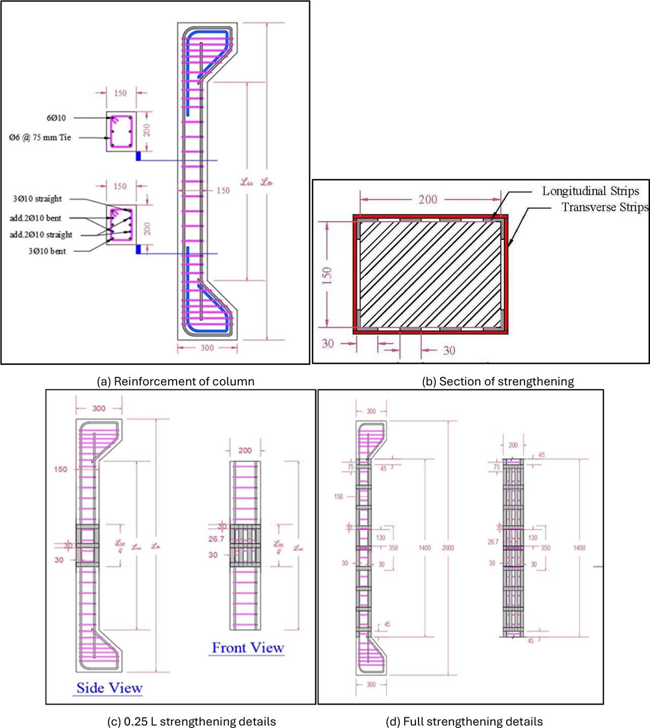
Figure 1:
Schematic details of column with strengthening
Furthermore, they were reinforced with longitudinal bars (6 Ø10), which provide a longitudinal steel ratio (ρg) of 1.42% [with the standards of the ACI 318M-19 Code (range 1 to 8%) (2019)], and Ø6 mm bars are used as transverse reinforcement (ties) at a spacing of 75 mm. Figure 1 (a) presents full details regarding the tested columns.
The laboratory test findings indicated that the longitudinal steel bar and tie had yield stress (fy) of 523 MPa and 505.13 MPa, respectively, while their ultimate stress (fu) was 605.04 MPa and 560 MPa, respectively. The studied columns contained corbels at each end that provided this type of eccentric load in accordance with the ACI 318M-19 requirements (2019). Thin strips of longitudinal and transverse steel plates, 30 mm wide and 0.5 mm thick, were placed in the middle of the column’s height, at a distance of 0.25 from its length and along its whole length to strengthen it. The necessary laboratory tests indicated that the steel plate had a yield stress (fy) of 221 MPa, while its ultimate stress (fu) was 297 MPa. Nails and epoxy are used for fixing the strips (Sikadur, 31/41 CF). Leisurely). Figure 1 (b - d) provides details about the strengthening.
2.3. Specimens Identification
The objective is to evaluate the columns by examining various factors, such as their length, eccentricity, and strengthening length. The primary variables in the experimental programme employed in this investigation are indicated in Table 1, which also identifies the examined columns.
2.4. Concrete Mix Proportions
All columns will be using self-compacting concrete (SCC), which is not considered as a variable in this study. The fresh concrete characteristics, such as filling capacity, passing ability, as well as viscosity, were evaluated through slump flow, T500, L-Box, and V-Funnel tests in compliance with ACI 237R (2007), as well as the standards set by EFNARC “the European Federation of National Associations for Representing SCC” (EFNARC-2002), show Figure 2. After many mixed trials, the design mixture was selected. It contained 350 kg/m3 of cement, 766.70 kg/m3 of coarse aggregate, 800 kg/m3 of fine aggregate, with 166.70 kg/m3 of limestone powder and 154 L/m3 of water. The water/cement ratio is 0.44 with 5.6 L/m3 (1.6% of cement weight) of superplasticizer (Sika ViscoCrete-180 GS). Since the design of the mix remained the same, the grade of concrete was the same for the columns and not a variable. The control cylinders had a length of 200 mm and a diameter of 100 mm, which were used for monitoring, and they had an average compressive strength (f’c) of 23.22 MPa.
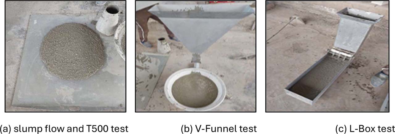
Figure 2:
Fresh concrete tests
2.5. Casting, Curing and Strengthening
Each wooden mould was cast individually, and the columns were fabricated in a horizontal configuration. Steel reinforcement cages were placed in the mould following the cleaning and oiling of the inner surfaces. The falling rotary mixer of 0.3 m3 was employed for mixing the mix of concrete. Figure 3 illustrates the processes of concrete mixing and casting.
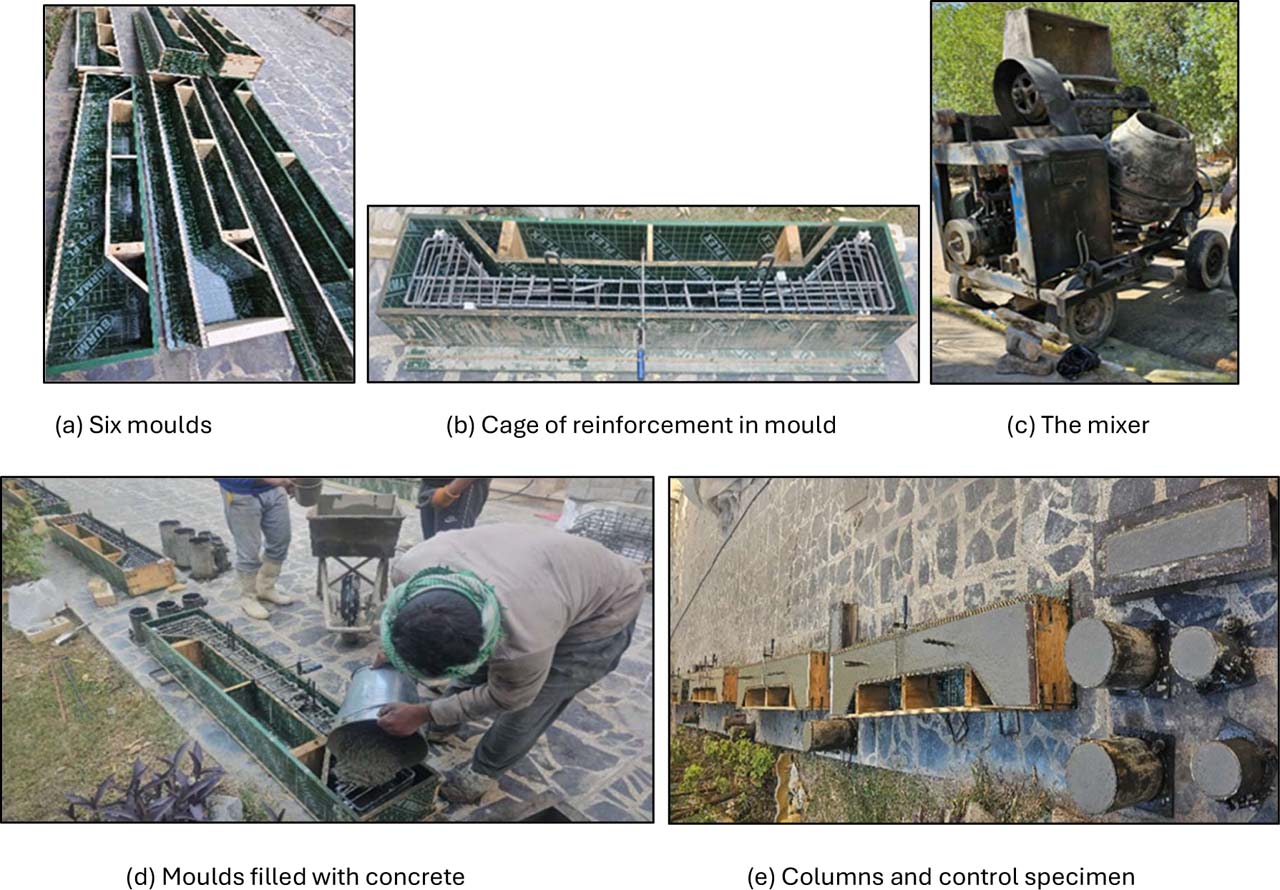
Figure 3:
Casting process of concrete
Following a 28-day curing period, shown in Figure 4, the surface of the concrete is readied to be strengthened using thin steel plates as transverse and longitudinal strips with the following procedures, as shown in Figure 5.
Grinding the concrete surface, cleaning, and corner warping.
All steel plate strips, both longitudinal and transverse, were cut to the specified lengths and measured.
A thin layer of epoxy (Sikadur-31/41 CF Slow) was applied to longitudinal strips. Longitudinal strips were applied to the concrete surface with pressure.
A thin layer of epoxy was applied to both the concrete surface and transverse strips; then the strips were placed on the concrete and pressed onto it to provide strong bonding without gaps.
As soon as the longitudinal and transverse strips were bonded with epoxy, nails were utilized to secure them firmly to the concrete.
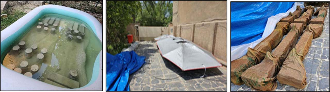
Figure 4:
Curing process

Figure 5:
Strengthening process
2.6. Testing Procedure and Instrumentation
A hydraulic testing instrument with an ultimate capacity of 250 tons was employed to supply a monotonic pressure to the columns. The constructed steel loading caps are used as supports at each end of the test column. The load is transferred to the loading cap by a wedge rod positioned in grooves at a 90 and 45 mm eccentricity to the column cross-section’s central point. The column’s length exhibits a consistent moment distribution due to the equal eccentricity of its upper and lower ends. This type of support functions as the hinged connector for the ends of the column. A load cell was positioned at the base of the device during the assessment to record the applied load. The strain in columns is assessed on each side (tension and compression) at the midpoint of their height, utilizing foil electrical strain sensors on concrete and steel. Figure 6 illustrates that the strain gauges are produced by the Japanese manufacturer TML, specifically the types FLAB-6-11-3LJC-F for steel and PL-60-11-3LJC-F for concrete.
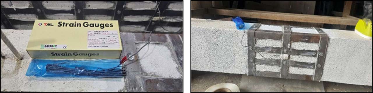
Figure 6:
Strain gage
Furthermore, two LVDTs were installed along the height of the column to quantify the axial and lateral displacement of the eccentric columns. To assess lateral displacement, one instrument was positioned at the mid-height of the column, and another was situated at the base of the machine to measure the reduction in length at any loading rate along the height of the column. All devices were connected to the data logger. The load-lateral displacement behaviour was assessed while the load was incrementally increased until it reached failure. While implementing additional safety precautions, cracking observations were recorded. The load capacity, crack pattern, and failure mode were carefully examined. Figure 7 shows the process of testing.
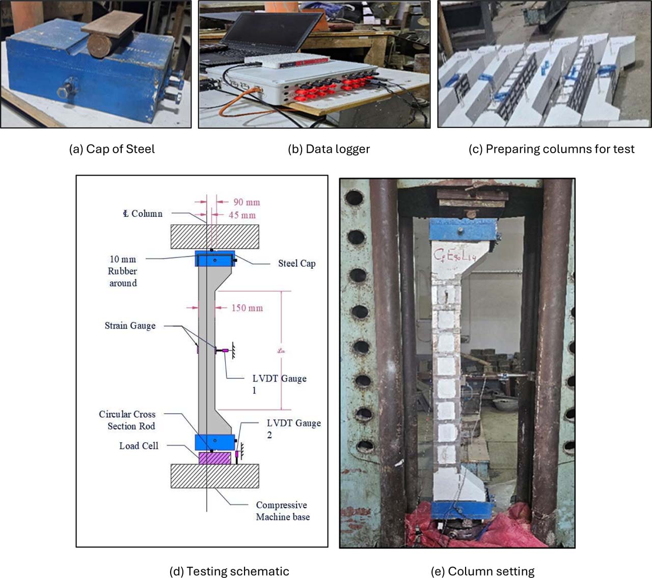
Figure 7:
Testing procedure and instrumentation
3. Test Results and Discussion
The results of the tested columns, involving the ultimate lateral deflection at the mid-height, first crack, ultimate load, and energy absorption capacity, are displayed for all columns in Table 2.
Table 2:
Test results of columns
| Groups | Col. No. | Column designation | First crack load Pcr [kN] | Ultimate load Pu test [kN] | Lateral displacement ∆L @ Pu [mm] | Energy absorption [EA] [kN.mm] | *Energy absorption capacity [EAC] [kN.mm/mm] |
|---|---|---|---|---|---|---|---|
| Without strength | 1 | C0E45L1.4 | 125 | 293.87 | 19.09 | 3836.81 | 201.00 |
| 2 | C0E90L1.4 | 60 | 136.02 | 19.25 | 1534.30 | 79.66 | |
| 0.25 L strength | 3 | C0.25E45L1.4 | 147 | 306.36 | 18.36 | 4045.90 | 220.40 |
| 4 | C0.25E90L1.4 | 65 | 151.68 | 18.606 | 1733.00 | 93.14 | |
| Full strength | 5 | Cf E45L1.4 | 165 | 360.04 | 18.09 | 4640.06 | 256.51 |
| 6 | Cf E90L1.4 | 160 | 185.75 | 18.28 | 2513.30 | 137.50 |
3.1. Hardened SCC Testes Results
Four important tests assess the mechanical properties of hardened concrete at 28 days: compressive strength, flexural strength, splitting tensile strength, and modulus of elasticity. Control samples were taken from the mixture, and the test results show the average value of three samples. The tests were conducted in accordance with ASTM specifications. Results from theory and experiments for all concrete hardening tests are shown in Table 3, which compares the testing results of hardened SCC with the theoretical results calculated using equations in accordance with ACI 318 M-19.
Table 3:
Results of testing hardened SCC
| Test | Compressive strength f′c [MPa] ASTM C39 / C39M | Splitting tensile strength ft [MPa] ASTM C496 | Flexural strength fr [MPa] ASTM C78 | Static modulus of elasticity Ec [GPa] ASTM C469 | |||
|---|---|---|---|---|---|---|---|
| Age (days) | 7 | 28 | 7 | 28 | 7 | 28 | 28 |
| Experimental results | 19.24 | 23.22 | 2.47 | 2.55 | 3.48 | 4.1 | 25.337 |
| Theoretical results calculated by ACI 318 M-19 formulas | 2.46 | 2.70 | 2.72 | 3.00 | 22.647 | ||
| Difference [%] | ---- | 94.4 | ---- | 137 | ---- | ||
3.2. Ultimate Load and Lateral Displacement
3.2.1. Second-order (P-∆ effect) and M-N Field
In RC slender columns, an increase in eccentricity increases the primary external bending moment (M1 = P.e), which decreases the load capacity (Sahi and Mohammed, 2021). In highly slender elements (kℓu/r = 31.11), this primary moment is significantly magnified by the second-order lateral deflection (P-∆ effect), creating a massive secondary moment (M2 = P. ∆). This shifts the failure configuration deeply into the tension-controlled zone of the M-N interaction diagram, where the ultimate load capacity (Pu) drops drastically due to early tensile yielding of the steel bars and extensive concrete macro-cracking.
Upon experimental verification of the results of the three groups shown in Table 2, we observe that moving from e= 45 mm to e= 90 mm (at the same strengthening) causes a decrease in load-bearing capacity due to the dominant second-order flexural tensile stresses of approximately 50%. This uniform drop of approx. 50 % across different strengthening schemes mathematically confirms the high consistency of our testing configuration and accurately reflects classic structural stability mechanics under high eccentricity.
3.2.2. Results of Ultimate Load and Lateral Displacement
The data in Table 2 show that RC slender columns that have been strengthened with different lengths of strengthening have better ultimate load and lateral displacement. Figure 8 shows that full column length strengthening leads to greater enhancements in the maximum load capacity and lateral mid-displacement than 0.25L strengthening. This phenomenon occurs because the confinement provided by strengthening resists the lateral expansion of the concrete (Poisson effect), which in turn increases the compressive strength of the core and prevents premature buckling (ACI PRC-440, 2017). This confinement mechanism and increased cross-sectional stiffness (EI) act as a means of improving the axial flexural response of columns.
The increase in ultimate load capacity is more effective than lateral mid-displacement in both loading situations and strengthening types. When comparing the same strengthening and eccentricity conditions, the ultimate load increase ratio is between 4.25% and 22.52% for e=45 mm and between 11.50% and 36.55% for e=90. This result indicates that the columns have become stiffer. Additionally, at full strengthening, the ultimate load capacity improvement for weaker columns (under e=90) is greater than that for stronger columns (under e=45), similar to columns strengthened with 0.25 length. This is because strengthening helps in preventing lateral displacement. As a result, the column cross-section will experience a reduced secondary bending moment (P-∆ effect).
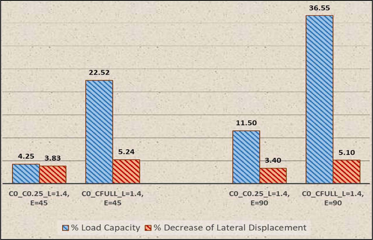
Figure 8:
Ratio between un-strengthened and strengthened columns for decrease of lateral displacement and load capacity (%)
Strengthening increases the column’s stiffness by reducing displacement as the ultimate load increases, as illustrated by the load-lateral deflection curve in Figure 9. Columns with full strengthening are more effective compared to columns without and with 0.25 L strengthening. This improvement is due to the continuous restraint along the entire height and increased cross-sectional stiffness (EI), effectively delaying failure and resisting the global buckling of the column (ACI PRC-440, 2017).
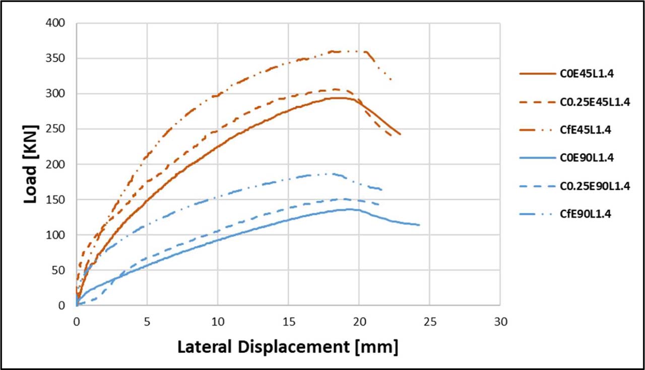
Figure 9:
Curve of load-lateral displacement at mid-height
3.3. Strain Results of Columns
Figures 10 and 11 illustrate the strain difference between strengthened and unstrengthened columns and show the following:
In Both the partial and full strengthening systems significantly reduce compressive and tensile strain compared to the reference specimens.
In the tension zone of unstrengthened columns, the tensile strains are significantly increased (reaching over 12,000–14,000 micro-strains), indicating severe cracking and bending, as shown in the failure mode.
The partially and fully strengthened specimens maintain near-vertical strain paths. This stiffening effect prevents rapid movement of the neutral axis, effectively confining the concrete and protecting the longitudinal steel from premature yielding.
Fully strengthened columns show a greater ultimate load capacity compared to other columns, coupled with massive strain development. This improvement is attributed to the continuous restraint and increased cross-sectional stiffness provided by the steel platesalong the entire height, effectively resisting the global buckling patterns associated with high slenderness ratios (ACI PRC-440, 2017).
An important observation in the load-strain curve is that partial strengthening at mid-height (0.25L) produces results very close to those of full strengthening. This is because mid-height is the location of maximum lateral deflection (∆) and maximum secondary moments. Strengthening this critical region significantly limits the effect of P-∆ (Teng et al., 2003). However, the fully strengthened column exhibits slightly better strain control, indicating a more uniform stress distribution.
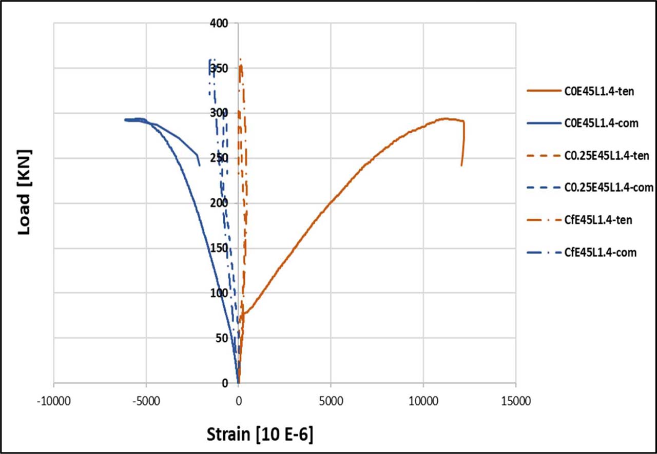
Figure 10:
Curve of load-strain at mid-height under - e (45)
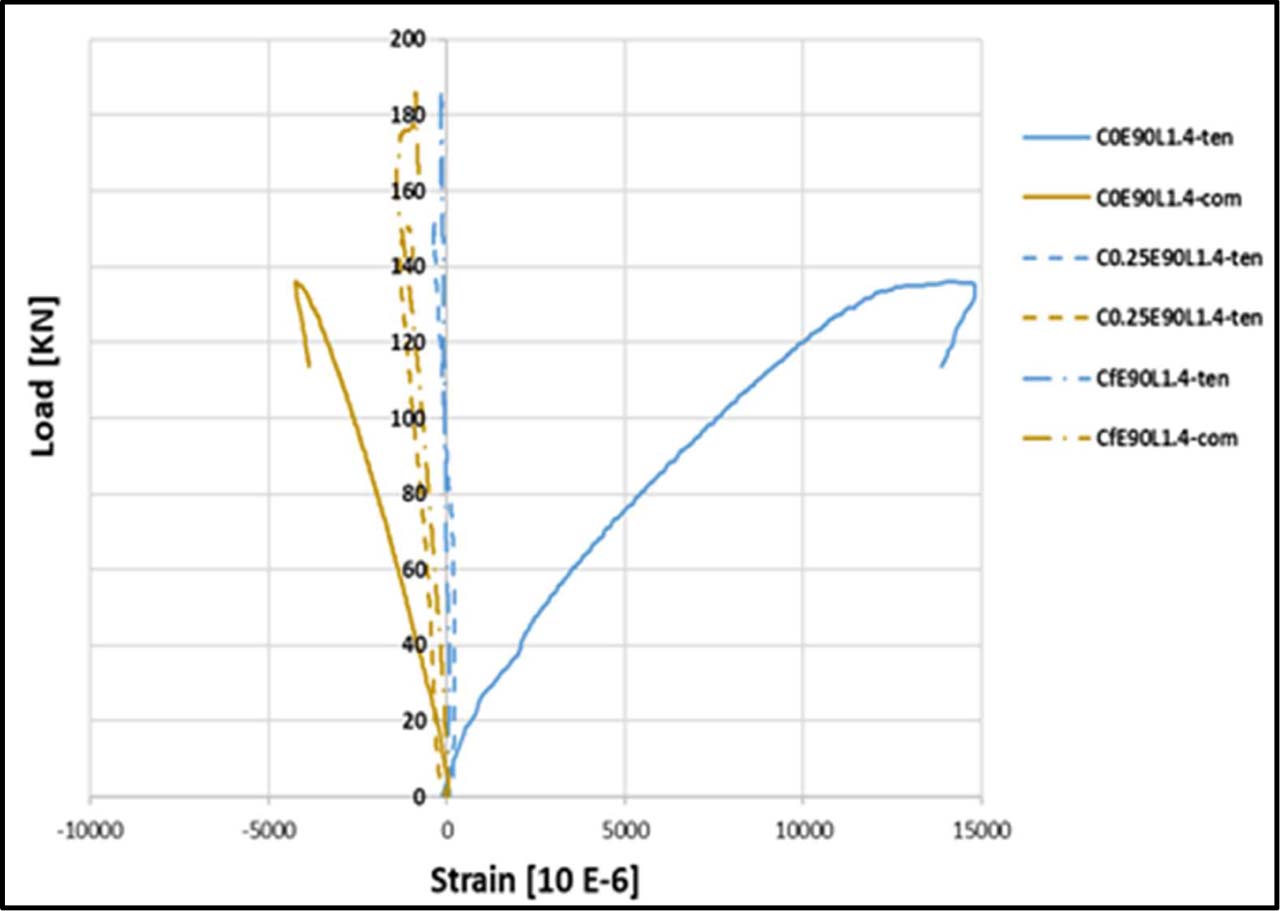
Figure 11:
Curve of load-strain at mid-height under - e (90)
Despite the eccentricity of loading producing moments of bending that can create localized tensile stresses, in slender columns, the axial load magnitude was adequately raised to move the neutral axis beyond the cross-section. Consequently, compressive strains were seen on both measured sides at mid-height. This behaviour is typical of slender columns, particularly under axial compression, together with second-order effects because global instability governs the response rather than pure flexural behaviour.
3.4. Energy Absorption
The capacity of energy absorption provides crucial information about the effectiveness of slender columns subjected to lateral stresses. An improved energy absorption capacity signifies more flexibility and the capability to endure dynamic loads. So, this knowledge is essential to inform structural design, particularly in areas exposed to earthquakes and other lateral loads; thus, it improves the stability as well as durability of structures. Thus, evaluating RC thin columns’ ability to absorb and dissipate energy is essential to understanding their behaviour (Lu, & Yu, 2003). The scientific designation for the area under the curve of load-lateral displacement is “Energy Absorption” or “Dissipated Energy.” The energy of the column is calculated before reaching its maximum deflection. The normalised value of “Energy Absorption Capacity” is calculated by dividing the dissipated energy by the ultimate lateral deflection (Lu, & Yu, 2003).
Table 2 and Figure 12 illustrate how the column’s strengthening has improved its capacity to absorb energy. Figure 13 shows that both 0.25 L and full strengthening significantly increase the efficiency of energy absorption capacity. Additionally, full strengthening improves energy absorption capacity more than 0.25 L strengthening, especially with eccentricity loads of 90. The improvement rates at e = 45 were 27.62% for full strengthening and 9.65% for 0.25 L. On the other hand, when e = 90, the improvement rates increased to 16.93% for 0.25 L strengthening and 72.63% for full strengthening.
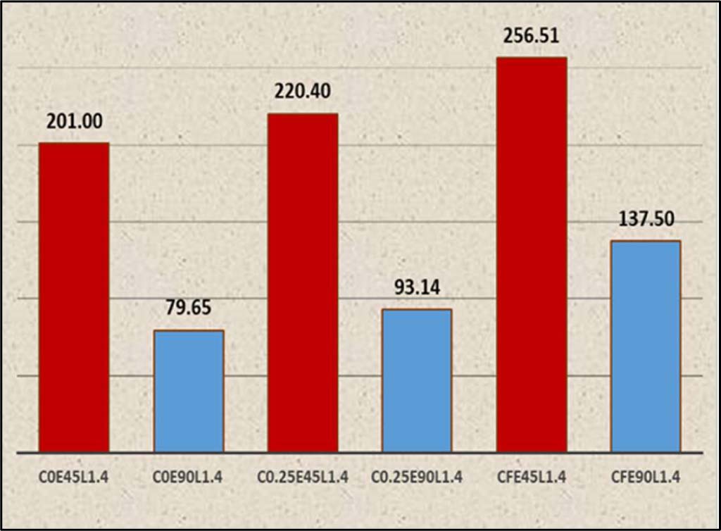
Figure 12:
Energy absorption capacity of tested columns (kN.mm/mm)
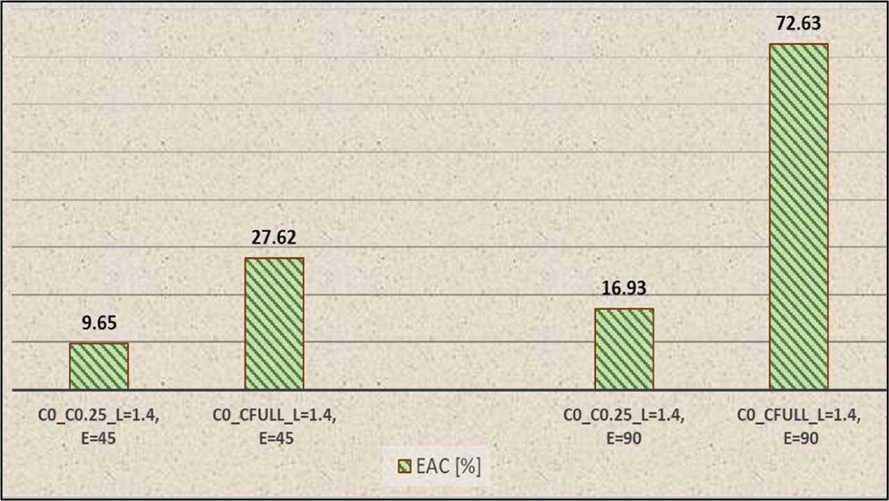
Figure 13:
Increase in energy absorption capacity of tested columns [%]
3.5. Mode of Failure and General Behaviour
In general, no obvious cracks were seen in the columns during the first loading phases. As the load incrementally increased from initial application until failure, cracks induced by compression and tension were observable and documented. Tension cracks were initially generated when applying an eccentric load. Cracks on the outer face (tension face) of the column began to form as the applied load increased, grew larger and more numerous along its height, and ultimately led to the column’s failure, as shown in Figure 14.
The strain measurements indicate localised responses at mid-height, while observed cracking behaviours and modes of failure are dictated by the global instability behaviour of the slender columns. Despite the existence of localised compressive loads, tensile cracking and buckling can happen in regions affected by lateral displacement and second-order deformation. Thus, the mechanism for failure is dictated by the overall instability of the column instead of the strain conditions at a specific cross-section.
The flexural crack numbers on the tensile side significantly rise along with column height during the failure of unstrengthened columns, as illustrated in Figures 15 and 16. The concrete is crushed and spalled on its compressive side due to fracture propagation occurring in the middle third. Additionally, buckling was most frequently considered a result of eccentricity, especially for e=90 m. Failure of the strengthened column with 0.25 L is shown in Figures 17 and 18. This signifies a substantial reduction in the number of cracks, with the failure location shifting either upward or downward from the strengthened area. This localized strengthening in the critical region, where maximum lateral displacement and secondary moments (P-∆ effects) limit lateral bulging (Poisson effect) and increase the flexural stiffness (EI) of this specific region. This causes the transfer of stress from the stronger region to the weaker region (unstrengthened boundaries). The steel strips within the strengthened zone remained fully intact and did not experience global epoxy debonding. However, localized buckling of the 0.5 mm longitudinal strips occurred on the compression side only at the very edge of the jacket due to the high stress concentration at the material discontinuity.
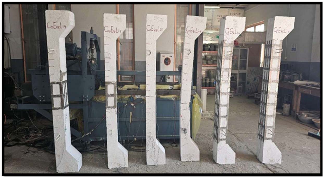
Figure 14:
Failure of all columns
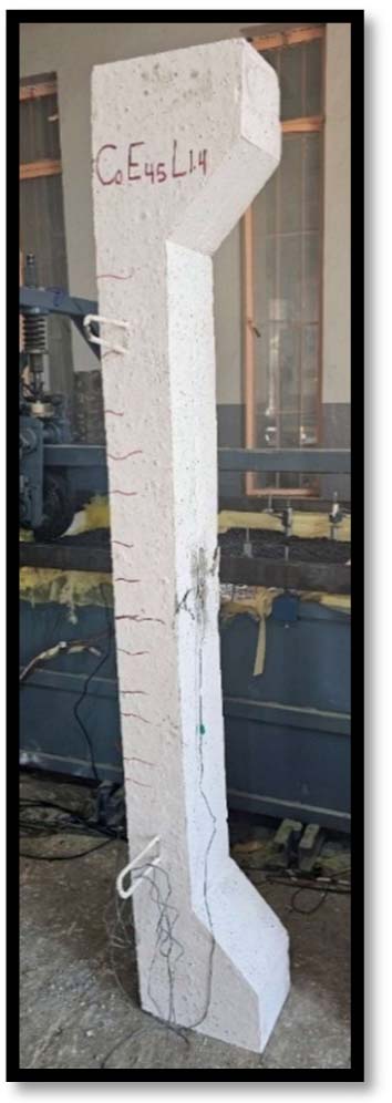
Figure 15:
C0E45L1.4
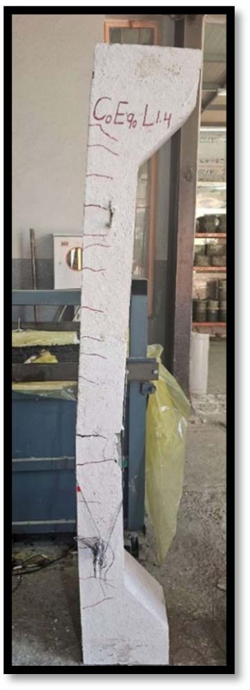
Figure 16:
C0E90L1.4
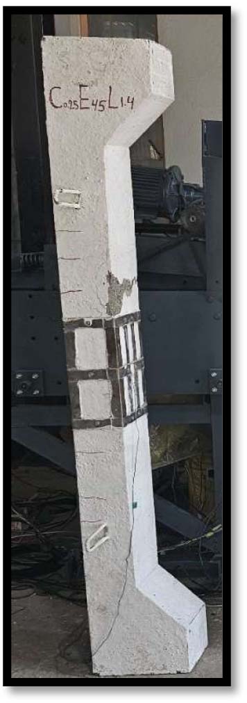
Figure 17:
C0.25E45L1.4
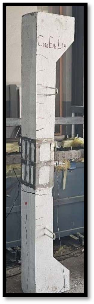
Figure 18:
C0.25E90L1.4
Figures 19 and 20 show that the strengthened columns with full length failed. When compared to strengthening with a length of 0.25 L, we see a bigger drop in the number of cracks and localised buckling in steel plate strips. This process causes the strips to come loose from the concrete and spall in the concrete cover below them.
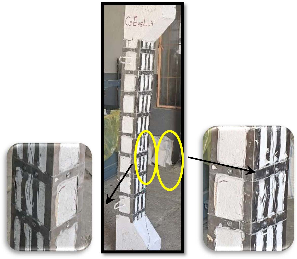
Figure 19:
Cf E45L1.4
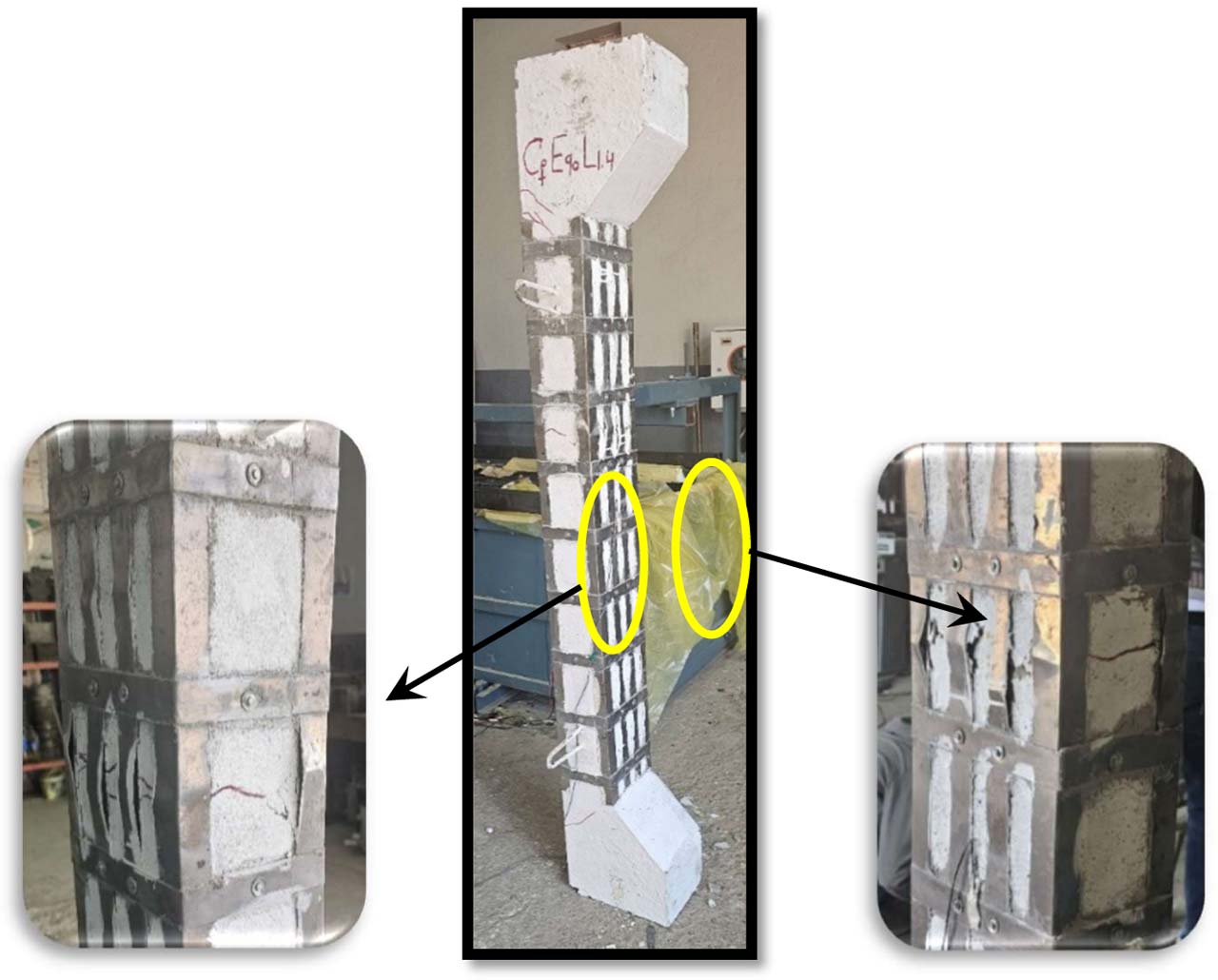
Figure 20:
Cf E90L1.4
To summarize, the column failed due to high compressive stress and deep and wide cracks created by the substantial lateral displacement resulting from continuing to apply the load eccentrically. This led to the failure of slender columns because of instability problems, not a lack of strength (Hassanein, 2014). Stresses are transmitted from a strong zone to a weak zone when the slender columns are strengthened by steel plate strips at 0.25 of the column’s height and the full length under eccentric loads.
As a result, the column’s bearing capacity is increased because failure is delayed and the location is changed (outside of the strengthened zone) (Abdel-Hay & Fawzy, 2015). Furthermore, increasing the height of strengthening (i.e., its full length) progressively improves the ductility and ultimate load capacity. Theoretically, the enhancement in the column’s load-bearing capacity should consistently correlate with the ratio of the length of the strengthened section (0.25 L and full). But in actuality (in this study), this increase happened quickly and at inconsistent rates when partial and full column strengthening were compared, as seen in Figure 8.
3.6. Strengthening Mechanism
The strengthening mechanism investigated in this research is purely passive. The steel strips do not experience initial stress until additional external load or lateral deformation (P-∆ deflection) takes place. The passive system activates as the concrete core undergoes lateral expansion (Poisson’s effect) and global second-order buckling deflection, triggering tensile stress in the transverse straps and longitudinal plates to arrest crack opening.
The use of exceptionally thin (0.5 mm) plates increases the vulnerability to localized plate buckling. The explicit engineering rationale for selecting an atypically thin steel plate (0.5 mm) is governed by two major factors:
Minimizing Cross-Sectional Encroachment and Self-Weight: Traditional heavy structural steel angles or thick plates fundamentally transform the structural geometry and dead weight of the member. This research specifically aimed to evaluate the boundary limit of an ultra-lightweight, low-cost, and non-invasive surface modification technique.
Confinement Mechanism under Eccentricity (e): In slender columns under high eccentricity (e/h = 0.6), the failure is predominantly driven by global lateral deflection and extensive tensile cracking on the tension face, rather than pure concentric crushing. The 0.5 mm longitudinal strips on the tension face acted effectively as external tension ties to control crack widths and retard lateral bending, while the transverse strips provided discrete confinement. On the compression face, although the 0.5 mm plates experienced localized buckling at late loading stages, this occurred only after the concrete had safely achieved its peak core capacity, effectively delayed the overall structural collapse and enhanced the energy absorption capacity up to 72.63%.
3.7. Strength Gain per Unit Steel Volume as an Indicator of Economic Efficiency for Strengthening
Table 4 illustrates the efficacy of the strengthening (0.25 L and full) utilizing 0.5 mm steel plate strips for slender columns subjected to eccentric loads (e = 45 mm and e = 90 mm). The relation between the ultimate test load and the volume of strengthening steel (∆Pu Test / Vol.); this proportion indicates the efficacy of the strengthening material per unit volume.
Table 4:
Ratio between Ultimate Test Load to Volume of Steel Strengthening (Efficiency Percentage)
| e [e/h] | Col. No. | Column designation | Ultimate load Pu Test [N] | *∆ Pu Test [N] | Volume of strengthening vol. [mm3] | ∆Pu test / vol. [Efficiency %] [N/mm3] |
|---|---|---|---|---|---|---|
| 45 [0.3] | 1 | C0E45L1.4 | 293.87×10³ | ---- | ---- | ---- |
| 2 | C0.25E45L1.4 | 306.36×10³ | 12490 | 94500 | 13.22 | |
| 3 | Cf E45L1.4 | 360.04×10³ | 66170 | 346500 | 19.10 | |
| 90 [0.6] | 4 | C0E90L1.4 | 136.03×10³ | ---- | ---- | ---- |
| 5 | C0.25E90L1.4 | 151.68×10³ | 15650 | 94500 | 16.56 | |
| 6 | Cf E90L1.4 | 185.75×10³ | 49720 | 346500 | 14.35 |
The data presented in Table 4 need the following points for discussion:
The percentage indicates the “structural efficiency” of the strengthening steel. This ratio represents the increased load capacity (∆Pu Test) obtained per cubic millimetre of steel used (Vol.). Furthermore, a greater percentage indicates that the strengthening material is being used more effectively.
When comparing columns with partial strengthening (0.25 L) to those with full strengthening at the same eccentricity, the following result is observed: Although the highest ultimate load is provided by full strengthening (∆ Pu Test), the efficiency ratio may be lower than that of partial jackets (at e=90). This indicates that strengthening the midpoint (0.25 L) of a slender column is the most economical strategy, as it addresses the area with the highest lateral deflection (maximum bending moment). Consequently, improving of the efficiency ratio with 0.25 L strengthening was apparent at the highest eccentricity (e=90). This means the 0.25L system offers an exceptionally optimized alternative for budget-restricted or weight-sensitive projects.
4. Conclusion
The research provides a substantial advantage by introducing a technique that serves as a practical, simple, and economical solution for strengthening RC slender columns, thereby offering a dependable and secure option for engineers in structural engineering. The results of the experiment about the use of thin steel plate (0.5 mm thick) as transverse and longitudinal strips placed at 0.25 length of the column at mid-height and along the full length to strengthen self-compacting RC slender columns, under various eccentric loading conditions, lead to the following conclusions:
When the eccentricity rises, the lateral displacement rises while load bearing capacity reduces for each strengthened and un-strengthened column.
Strengthening an RC slender column makes it stiffer by increasing its load-bearing capacity and reducing lateral displacement. This is higher with fully strengthened columns.
This strengthening significantly improved the energy absorption, especially the full strengthening and under eccentric loads of 90, making it effective in earthquake-prone areas.
Strengthening significantly improves the behaviour of weaker columns (under e=90) more than stronger columns (under e=45).
Continuous strengthening along the column’s height prevents spalling and delays failure through improved confinement.
The strengthening caused the failure point to move outside of the strengthened zone and altered the stress distribution throughout the column height. This result suggests that the chosen length of strengthening (0.25L), although efficient in postponing failure, may be inadequate to fully manage instability in excessively slender columns. Therefore, the whole strengthening is more efficient.
The enhancement of the column’s bearing capacity is irregularly correlated with the length of the strengthened portion, exhibiting quick and inconsistent increases when contrasting partial and full column strengthening.
Regarding strengthening efficiency, mid-height partial strengthening appeared as an economical and structurally optimized method to reduce global buckling, resulting in the greatest load increase relative to the volume of steel employed, especially under conditions of high eccentricity.
5. Recommendations
The authors would like to recommend the following:
Use thin steel plate sheets instead of steel plate strips and in different lengths.
For lower cost and economy, study the effect of this technique using cement grout (bonding) instead of epoxy grout.
Study the same technique with different cross-sections of slender columns, like circular.
Expand the research’s scope by employing other loads, such as cyclic loads, biaxial loading, and higher eccentricity (more than 90 mm).
Notes
[3] Contributed by Author Contributions
B.R. designed the study and supervised the project. A.S. conducted the experiments, contributed to manuscript writing. A.S. and B.R. performed the data analysis. All authors critically reviewed and approved the final version of the manuscript and agreed to be accountable for all aspects of the work.