

1. Introduction
Precast concrete sandwich panels (PCSPs) are extensively used in structural and building applications since they provide sufficient structural capacity collected with thermal and acoustic insulation (Losch, 2005; Maximos et al., 2007; PCI Committee on Precast Concrete Sandwich Wall Panels, 1997). Basically, these panels be composed of two concrete wythes separated by a core layer and connected over shear connectors, whose adeptness and arrangement govern the degree of composite action (Frankl et al., 2011). Sandwich wall panels (SWPs) are also widely used as building envelope systems to develop the energy performance of buildings by integrating an insulation core (Kim & Allard, 2014; Naito et al., 2011). Conventional insulation materials, for example polystyrene, styrofoam, and mineral wool, provide excellent thermal insulation but own limited mechanical strength, restricting their use as structural core materials. To address this limitation, various SWP systems integrating energy-efficient structural cores have been suggested to improve both thermal insulation and structural performance (Benayoune et al., 2007; Bush & Wu, 1998; Chen et al., 2015; Einea, 1991; Liew & Sohel, 2010; Tomlinson & Fam, 2015). ). Lately, foamed concrete (FC) has emerged as a promising lightweight and energy-efficient core material for sandwich panels. It is a cementitious material comprising a high volume of entrained air (usually more than 20%), which affords low density and good thermal insulation (Amran et al., 2015; Ramamurthy et al., 2009). Furthermore, FC is a flowable, self-compacting material appropriate for prefabrication (Aldridge, 2005) and has been usually used in engineering applications, including crack filling, Soil stabilization, and lightweight construction (Mindess, 2019). Nevertheless, its comparatively low tensile strength and brittle behaviour limit its structural applications. To overcome these limits, fibre reinforcement has been combined into FC, causing in enhanced compressive (Al-Sibahy & Edwards, 2017), tensile (Al-Sibahy & Edwards, 2012), and flexural strengths, together with improved ductility because of changes in the failure mode (Castillo-Lara et al., 2020; Falliano et al., 2019). Recent studies have more confirmed its potential, with (Li et al., 2024) proving that the flexural behaviour and failure mode of composite sandwich wall panels are strongly affected by the interaction between the foamed concrete core and the structural configuration. Mechanically, sandwich panels are primarily exposed to flexural and axial loads. Flexural performance is mainly important for elements exposed to lateral actions, such as wind and seismic loads, where the response is governed by out-of-plane bending. Among the obtainable test methods, the four-point bending test is widely adopted because it offers a constant moment region and allows an accurate evaluation of flexural behaviour (Ge et al., 2024; O’Hegarty & Kinnane, 2020; Oliveira et al., 2020; Zhao et al., 2024). It is usually preferred over the three-point bending test, which combines bending and shear effects (Sah et al., 2024). Axial compression behaviour is also significant for load-bearing applications (Al-Sibahy, 2016). Numerous researchers have investigated the flexural behaviour of sandwich panels. (Frazão et al., 2018) stated that incorporating sisal fibres, principally longer fibres, enhanced flexural strength. (Flores-Johnson & Li, 2012) proved that fibre-reinforced foamed concrete cores united with steel face sheets improved the load-carrying capacity. Also, (Prabha et al., 2018) reported improved flexural performance in sandwich panels integrating polypropylene fibre-reinforced foamed concrete cores and steel face sheets. Regarding compressive performance, (Carbonari et al., 2013) recognized failure mechanisms related with combined compression–bending and connector instability under axial loading. (Goh et al., 2016) developed a finite element model for foamed concrete sandwich panels; nevertheless, the model was not experimentally validated and did not consider the contribution of the insulation layer. (Mydin & Wang, 2011) proved that steel face sheets considerably improved ductility and load-carrying capacity compared with bare foamed concrete, while (Prabha et al., 2017) stated satisfactory lateral performance of steel–foamed concrete composite panels. Further recently, Ge et al. (2025) confirmed that rib configuration significantly effects the degree of composite action and flexural stiffness of sandwich panels, highlighting the importance of rib geometry in achieving effectual load transfer and enhanced structural performance. Further recently, (Ge et al., 2025) confirmed that rib configuration significantly effects the degree of composite action and flexural stiffness of sandwich panels, highlighting the importance of rib geometry in achieving effectual load transfer and enhanced structural performance. (Barbosa et al., 2023) also exhibited that precast sandwich panels can achieve sufficient composite action through actual shear connectors, even with reduced wythe thickness. Though numerous studies have studied the flexural and compressive behaviour of precast sandwich panels, most have focused on systems integrating conventional insulation cores, such as expanded polystyrene (EPS), or flat steel face sheets. There is still a lack of experimental studies on steel-faced ribbed sandwich panels with foamed concrete cores. A recent review by (Yan et al., 2024) highlighted that connector systems, composite action, and structural configuration are basic factors governing the flexural and compressive behaviour of steel–concrete sandwich structures. Nevertheless, experimental investigations addressing the combined effect of rib spacing and mechanical connector arrangement in steel-faced foamed concrete sandwich panels remain limited. Particularly, the interaction between corrugated rib spacing and shear connector arrangement under flexural and axial compression loading has not been sufficiently characterized through large-scale experimental testing, to the best of the authors’ knowledge. Consequently, the current study experimentally investigated the flexural and axial compression behaviour of steel-faced ribbed sandwich panels with foamed concrete cores. The study focused on the load–displacement response, load-carrying capacity, and the effect of rib spacing and shear connector arrangement on the overall structural performance of the panels.
2. Experimental Program
A series of experiments were conducted to determine the flexural and uniaxial compressive behaviour of foam concrete–filled sandwich panels. The following sections present the material properties, details of the sandwich panel fabrication, preparation and casting of the foam concrete core, test setup and the parameters monitored during the testing program.
2.1. Ribbed Steel Face Sheets Geometry
The sandwich panels under investigation in the current research consisted of ribbed (corrugated) steel faces sheets and a foamed concrete (FC) core. The steel face sheets were of nominal thickness 10 mm and were mechanically profiled to provide ribbed sheets to improve the stiffness and strength-to-weight ratio of the composite sandwich panels, as illustrated in Figure 1. The experimental program involved two rib spacing arrangements to study the influence of this variable on the behaviour of the panels, 10 cm and 15 cm.
The geometric details of the sandwich panel specimens used in the present study are illustrated in Figure 2. The schematic drawings include the specimen dimensions and the adopted rib spacing configurations for both flexural and axial compression tests. The flexural specimens had overall dimensions of 900 × 900 mm, whereas the axial compression specimens measured 600 × 600 mm.
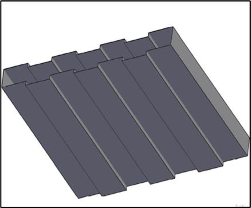
Figure 1:
Representative Schematic view of the ribbed steel face-sheet geometry used in the sandwich panels
2.2. Foam Concrete Core
The core material involved of foamed concrete with a constant thickness of 75 mm. Two different mixes were advanced: the first mix (M1) with an aim compressive strength of 2.5 MPa, and the second mix (M2) with an aim compressive strength of 4.0 MPa. The foamed concrete was. prepared using ordinary Portland cement, fine sand, water, silica fume, glass fibre, polypropylene, and pre-formed foam produced using a chemical foaming agent commercially well-known as SMC, which was diluted with water at a ratio of 1:40 as presented in Table 1. The foam was presented gradually into the cementitious slurry to gain a homogeneous mixture with controlled density and constant air void distribution, as presented in Figure 3. Small specimen cubes and cylinders were also prepared to determine the physical and mechanical properties of the foamed concrete, as presented in Figure 4. Water absorption, porosity, and dry density were measured at 7 and 28 days in agreement with ASTM C642. Compressive strength was determined following ASTM C109/C109M, and splitting tensile strength was measured agreeing to ASTM C496/C496M at curing ages of 7, 28, and 56 days. After casting and curing, the advanced mixes were tested to determine their Dry density, water absorption, porosity, compressive strength, and splitting tensile strength. The obtained results are presented in Table 2.
Table 1:
Mix proportion of the adopted foamed concrete mixes
| Mix ID | ||
|---|---|---|
| M1 by weight | M2 by weight | |
| Cement [kg/m3] | 180 | 450 |
| Water [kg] | 125 | 183.2 |
| Sand [kg/m3] | 200 | 292.5 |
| Silica fume [kg/m3] | 20 | - |
| Fibers [kg/m3] | 0.9 [glass fibre] | 0.9 [polypropylene fibre] |
| Foam [kg/m3] | 44 | 44 |
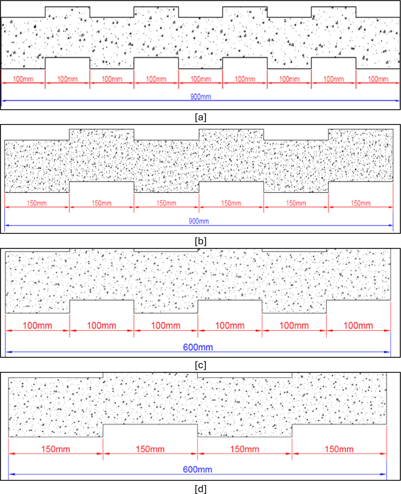
Figure 2:
Ribbed sandwich panel specimen [a] Cross-section of the ribbed sandwich panel specimen (R10) [900*900 mm], [b] Cross-section of the ribbed sandwich panel specimen (R15) [900*900 mm], [c] Cross-section of the ribbed sandwich panel specimen (R10) [600*600 mm], [d] Cross-section of the ribbed sandwich panel specimen (R15) [600*600 mm]
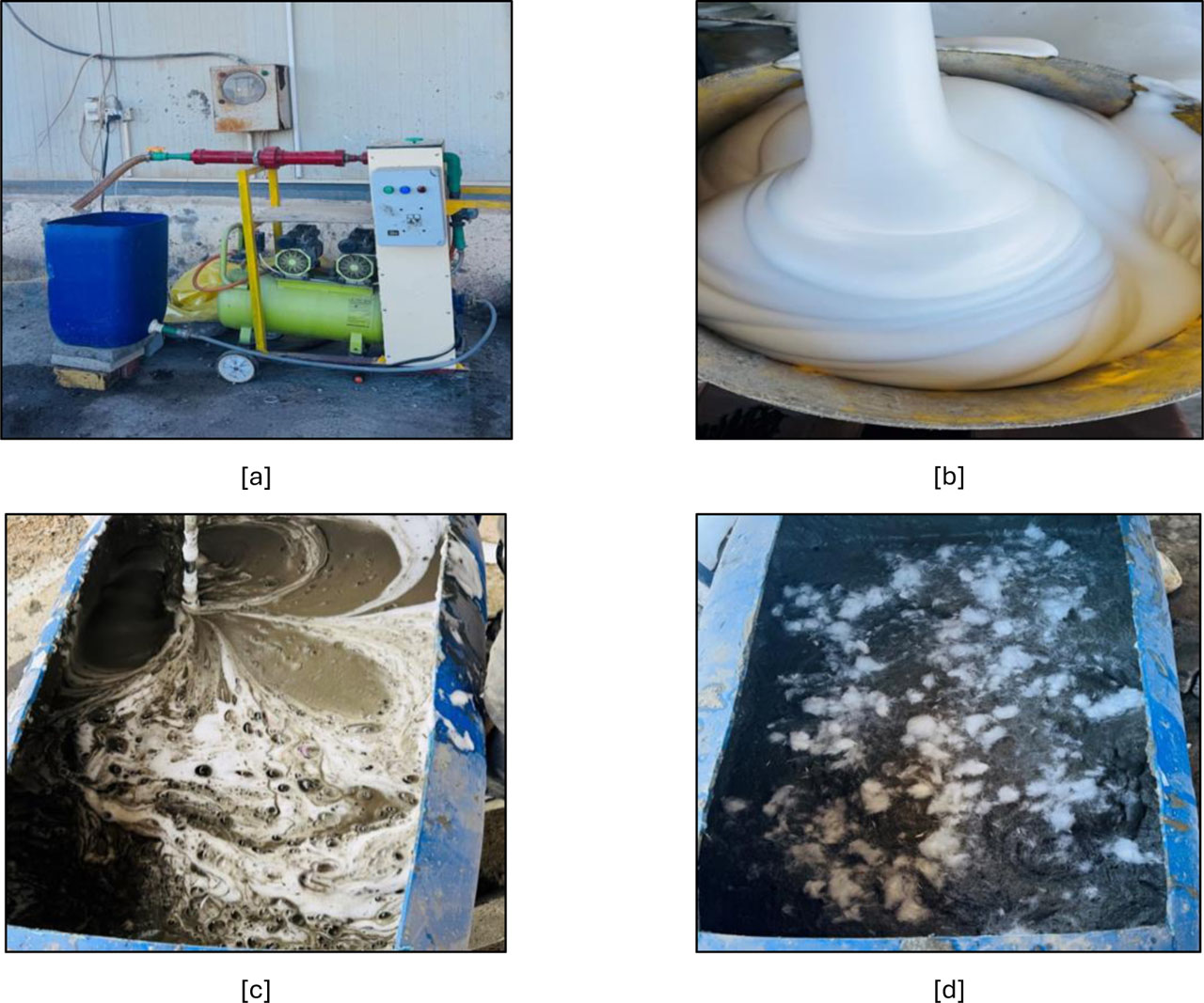
Figure 3:
Foam preparation process [a] foam generation device, [b] pre-formed foam used in the production of foamed concrete, [c] foam addition into the cementitious slurry, fibre addition to the concrete mixture
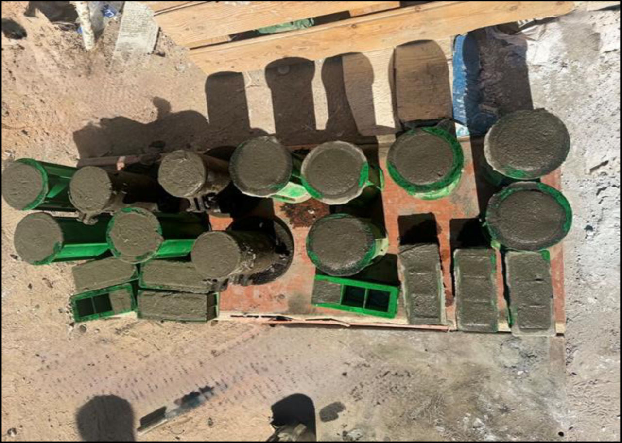
Figure 4:
Small foamed concrete specimen cast for laboratory testing
Table 2:
Average physical and mechanical properties of foamed concrete mixes at 7, 28, 56 days
| Mix | ||||||
|---|---|---|---|---|---|---|
| M1 | M1 | M1 | M2 | M2 | M2 | |
| Age [days] | 7 | 28 | 56 | 7 | 28 | 56 |
| Dry density [kg/m3] | 895.65 | 841.00 | - | 1125.75 | 1336.00 | - |
| Water Absorption [%] | 24.00 | 20.65 | - | 18.50 | 16.80 | - |
| Porosity [%] | 60.06 | 61.11 | - | 47.66 | 41.21 | - |
| Compressive strength [MPa] | 1.16 | 2.00 | 2.77 | 1.88 | 2.97 | 4.43 |
| Splitting tensile strength [MPa] | 0.115 | 0.123 | 0.86 | 0.445 | 0.676 | 1.024 |
2.3. Shear connectors
To ensure composite action between the steel face sheets and the foam concrete core, steel bolt shear connectors in the form of M10 bolts (grade 8.8) were used, as shown in Figure 5. Each connector had a length of 75 mm, matching to the thickness of the foam concrete core. The connectors were installed through the panel thickness to transfer shear forces, decrease interfacial slip, and improve the interaction between the steel facings and the core material. Two connector configurations were assumed in the current study, involving of 6 and 9 connectors per panel, arranged in a staggered pattern. In adding to their application in the sandwich panel specimens, the adopted mechanical connectors were experimentally assessed by means of a single shear test, as offered in the following subsection.
2.4. Fabrication of Sandwich Panel Specimens
Before casting, the inner surfaces of the ribbed steel face sheets were systematically cleaned to remove dust, oil, and other contaminants in order ensure proper bonding conditions between the steel facings and the foamed concrete core. The sandwich panels were made-up in a vertical casting position, where the two steel face sheets were fixed in place with the mechanical connectors installed between them. The pre-formed foamed concrete mixture was then poured between the steel facings to attain a uniform core thickness throughout the panel. After casting, all specimens were cured below laboratory conditions using air curing for a period of 28 days to ensure passable strength development of the foamed concrete core. Two panel sizes were prepared according to the loading conditions considered in this study. For the flexural tests (four-point bending), panels with plan dimensions of 900 × 900 mm were fabricated. For the axial compression tests, smaller panels with plan dimensions of 600 × 600 mm were prepared. The fabrication process of the sandwich panel specimens is shown in Figure 6 and 7.
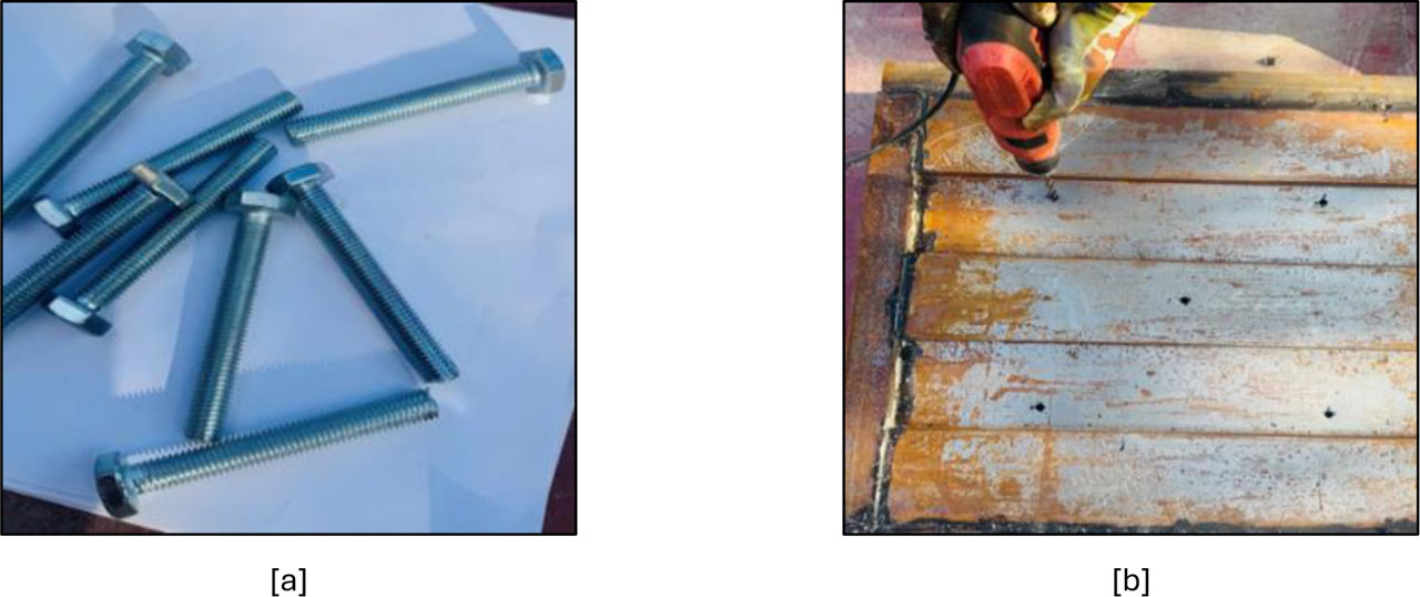
Figure 5:
Shear connectors used in the sandwich panel specimens [a] M10 bolt connectors [grade 8.8], [b] installation layout of the connectors in the panel
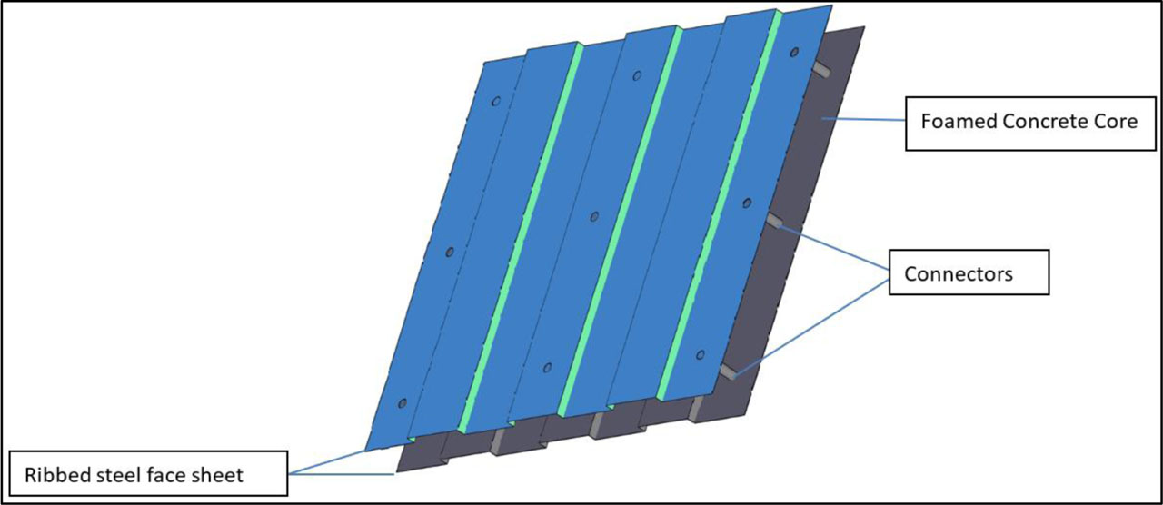
Figure 6:
Schematic drawing of a sandwich panel
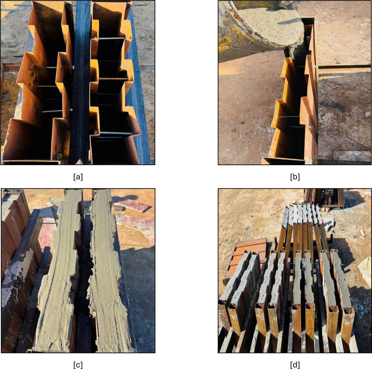
Figure 7:
Fabrication process of sandwich panel specimens, [a] ribbed steel face sheets and connectors, [b] casting of foamed concrete core, [c] casting of core, [d] splicing of sandwich panel specimens
A total of 16 sandwich panels were tested. (8 specimens) were subjected to four-point bending, and (8 specimens) were tested under axial compression. The sandwich panel specimens used in the experimental program are shown in Table 3 and Figure 8.
Table 3:
Details of specimens tested under four-point bending
| Specimen ID | Mix Type | Rib Spacing [mm] | No. of Connectors | Face sheet thickness [mm] | Core thickness [mm] |
|---|---|---|---|---|---|
| M1-R10-C6 | M1 | 10 | 6 | 10 | 75 |
| M1-R10-C9 | M1 | 10 | 9 | 10 | 75 |
| M1-R15-C6 | M1 | 15 | 6 | 10 | 75 |
| M1-R15-C9 | M1 | 15 | 9 | 10 | 75 |
| M2-R10-C6 | M2 | 10 | 6 | 10 | 75 |
| M2-R10-C9 | M2 | 10 | 9 | 10 | 75 |
| M2-R15-C6 | M2 | 15 | 6 | 10 | 75 |
| M2-R15-C9 | M2 | 15 | 9 | 10 | 75 |
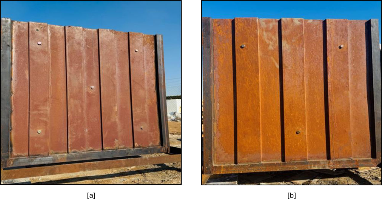
Figure 8:
Typical steel-faced foamed concrete sandwich panel specimens
3. Test Setup
3.1. Single Shear Test of Connectors
Three independent single shear tests were performed to determine the shear performance of the steel bolt connectors. The test was performed using an M10 bolt connector (class 8.8) in a universal testing machine (UTM) armed with a shear test fixture, as shown in Figure 9. During the test, the applied load and the conforming displacement were recorded constantly until failure. The nominal shear stress was determined using the relation τ= P/A, where A = πd^2/4 and d = 10 (mm), giving a connector cross-sectional area of 78.5 mm2.
The average results of the three single shear tests are shown in Table 4. The tested M10 connector reached an ultimate load of 34 KN at a displacement of 13.14 mm, corresponding to a nominal shear stress of 433.12 MPa. The detected failure mode of the tested connector after the single shear test is presented in Figure 10. These results show that the adopted connector provided adequate shear resistance and load-transfer capacity, supporting its efficiency in enhancing the composite action between the steel face sheets and the foamed concrete core.
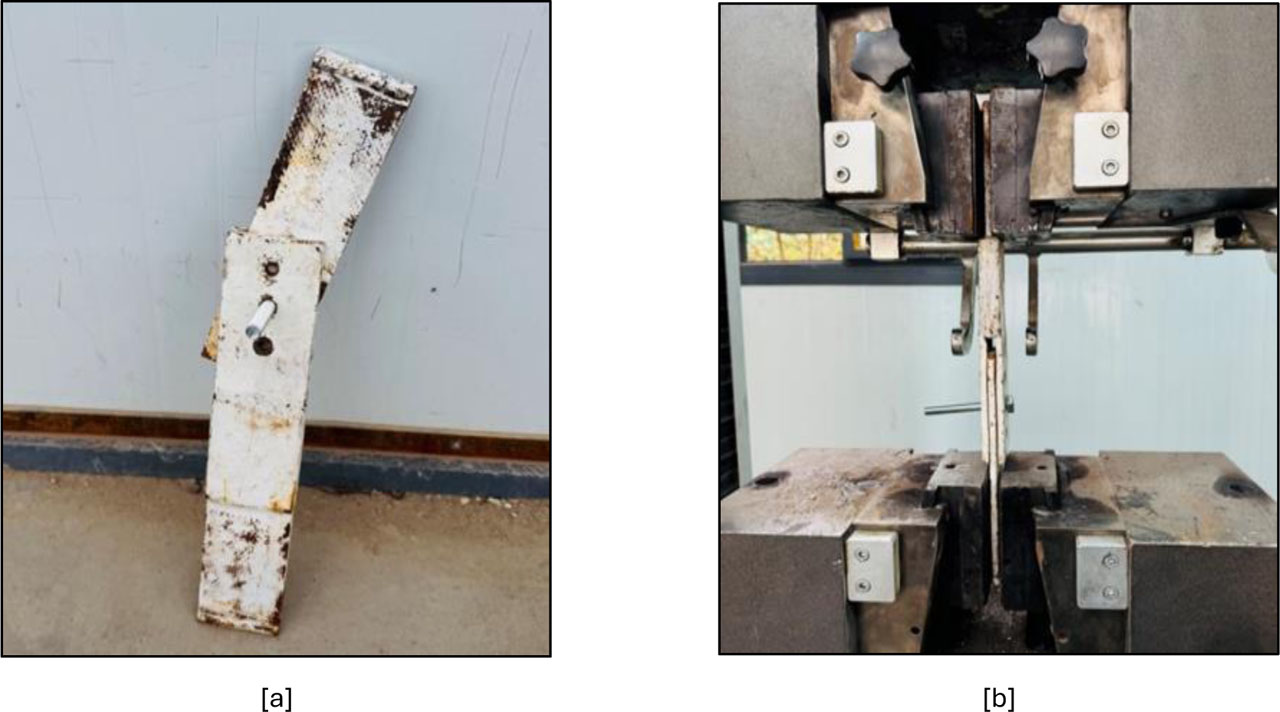
Figure 9:
Single shear test arrangement, [a] connector specimen, [b] loading setup in the universal testing machine
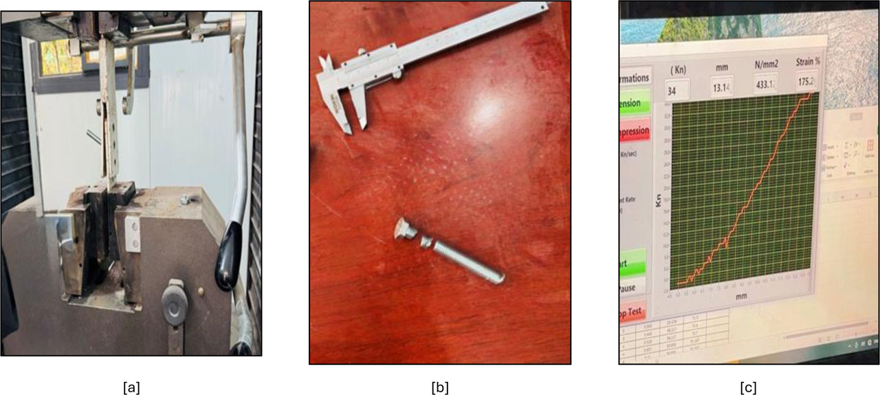
Figure 10:
Single shear test of the M10 connector [a] connector failure during testing, [b] tested connector after deformation, [c] load–displacement response
3.2. Four-Point Bending Test Setup
Four-point bending tests were conducted to assess the flexural behaviour of the steel-faced ribbed foamed-concrete sandwich panels in accord with ASTM D7249/D7249M–12. Each specimen had a total length of 900 mm and was simply supported over a clear span of 850 mm. Two concentrated loads were applied regularly through a rigid steel loading system, with a spacing of 300 mm between the loading points, producing a constant bending moment region at mid-span. The distance from each support to the near loading point was 275 mm, with a 25 mm overhang at both ends. The schematic configuration of the four-point bending test and the corresponding geometric parameters are shown in Figures 11 and 12. Mid-span displacement was measured using a digital dial gauge positioned at the centre of the specimen within the constant moment region. Load and displacement readings were constantly recorded during the test until failure. Furthermore, to the load–displacement response, the load corresponding to the first observable crack (first-crack load), the ultimate load capacity, and the failure mode were identified and documented.
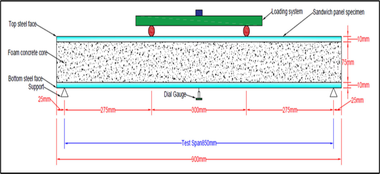
Figure 11:
Schematic diagram of the four-point bending test setup for the sandwich panel specimen
3.3. Axial Compression Test
Axial compression tests were conducted to study the structural performance of steel-faced ribbed foamed-concrete sandwich panel specimens subjected to uniaxial compression loading. The specimens had dimensions of 600 × 600 mm and were placed vertically between two rigid steel loading plates to ensure constant distribution of the applied load across the panel surface. The tests were made using a universal testing machine (UTM) under load-controlled conditions. The axial load was applied incrementally in phases of 5 kN until failure. The applied load was examined through the machine pressure gauge, while the deformation response of the specimens was measured using two digital dial gauges installed at mid-height of the panel. One dial gauge was settled horizontally to measure the lateral (out-of-plane) displacement, while the second dial gauge was located vertically to record the axial shortening of the specimen. At each load increase, the corresponding horizontal and vertical displacement readings were documented. Furthermore, to the load–displacement response, the first observable cracking, local buckling of the steel face sheets, face–core debonding, and the ultimate failure load were carefully detected and documented. The axial compression test configuration and instrumentation used in this study are shown in Figure 13.
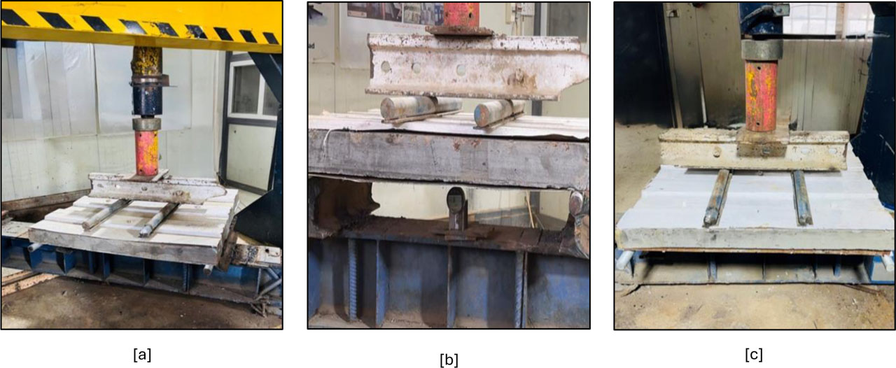
Figure 12:
Four-point bending test configuration used to evaluate the flexural behaviour of the sandwich panel specimens [a] overall experimental setup, [b] loading and support arrangement, [c] measurement of mid-span displacement using a digital dial gauge
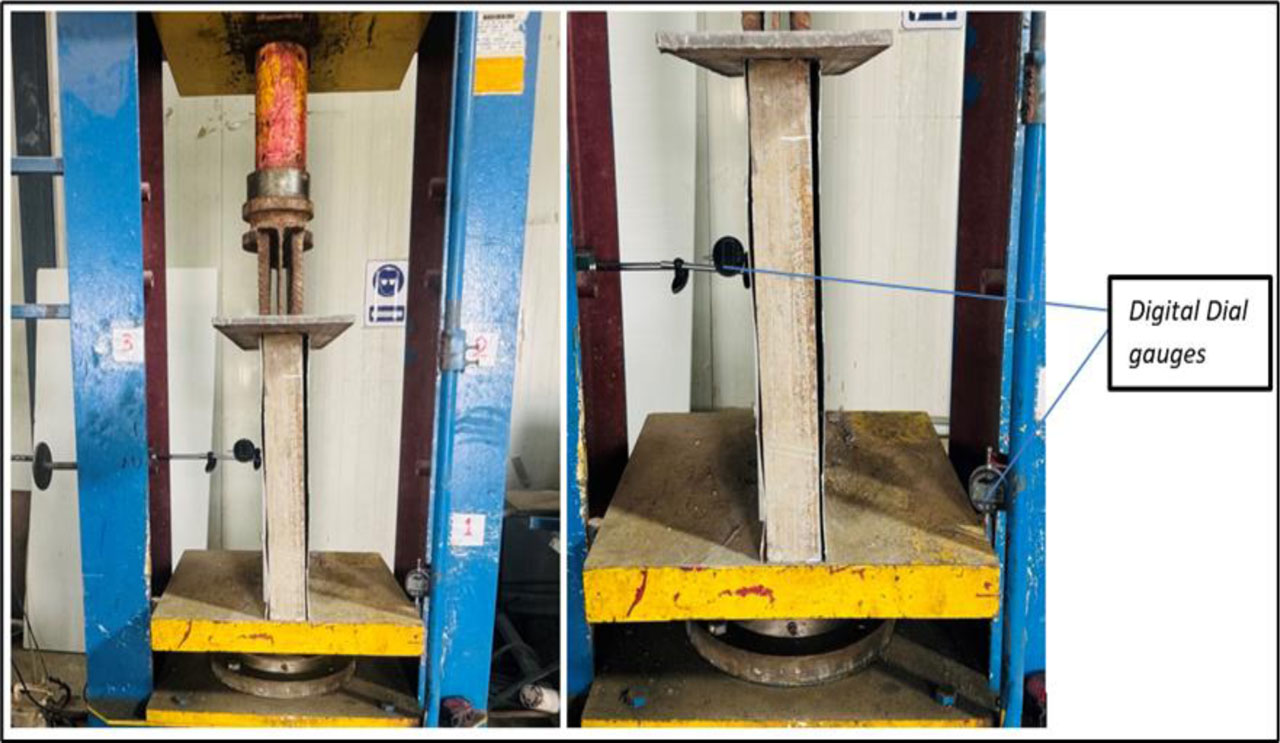
Figure 13:
Configuration of axial compression test, sandwich panel is loaded between two rigid steel plates, and the lateral displacement of the sandwich panel is measured by a dial gauge
4. Results and Discussions
4.1. Flexural Test Result
Table 5 and figures 14 to 16 display the results obtained from the four-point bending tests for all tested sandwich panel specimens, counting the ultimate load (Pu), ultimate bending moment (Mu), deflection at ultimate load (Δu), first crack load (Pcr), and the corresponding deflection at crack initiation. The results show that the flexural performance of the sandwich panels is governed by the combined effect of connector number and rib spacing, which straight affect the composite interaction, structural stiffness, and moment resistance of the system. Figure 14 [a] compares the load–displacement curves of specimens M1-R10-C6 and M1-R10-C9, where the rib spacing is retained constant while the number of connectors differs. It can be detected that growing the number of connectors from 6 to 9 enhanced the initial stiffness and ultimate load capacity of the panel. Specifically, the ultimate load capacity increased by 50% when the number of connectors increased from 6 to 9. The specimen M1-R10-C9 showed a steeper initial slope, representing higher flexural stiffness and enhanced resistance to deformation. This improvement is credited to the stronger composite action between the steel face sheets and the foam concrete core. The added connectors progress the shear transfer across the steel–concrete interface, so reducing interfacial slip and allowing the two materials to act more efficiently as a unified structural element. Consequently, the bending resistance and the actual moment capacity of the panel increased.
A similar trend is detected in Figure 14 [b], where specimens M1-R15-C6 and M1-R15-C9 are compared. Though increasing the connector number still improves the structural performance, the improvement is smaller than that detected in the R10 specimens. This behaviour can be clarified by the larger rib spacing (R15), which decreases the overall confinement and reductions the efficiency of load transfer between the steel faces and the core material. Therefore, the interface interaction becomes less effective, leading to lower structural stiffness and reduced bending resistance. The influence of rib spacing is further shown in Figure 14 [c], which compares M1-R10-C6 and M1-R15-C6 while keeping a constant number of connectors. The specimen with R10 rib spacing visibly demonstrates higher stiffness and load capacity than the R15 specimen. This behaviour can be credited to the increased actual surface interaction area between the steel faces and the foam concrete core providing by the closer rib spacing. A smaller rib spacing rises the structural confinement and develops the effective moment of inertia of the composite section, which in turn rises the bending stiffness and overall rigidity of the panel. A similar comparison is offered in Figure 14 [d] between M1-R10-C9 and M1-R15-C9. The specimen with R10 spacing again shown superior flexural performance compared with the R15 specimen.
Table 5:
Four-point flexural strength test results
| Specimen ID | Ultimate load Pu [kN] | Ultimate flexural strength Mu [kN.m] | Deflection at ultimate load ∆u [mm] | First crack load Pcr [kN] | First Crack moment Mcr [kN.m] | Deflection at first crack ∆cr [mm] | Failure mode |
|---|---|---|---|---|---|---|---|
| M1-R10-C6 | 22 | 3.025 | 9.28 | 20 | 2.75 | 7.50 | Local outward bulging |
| M1-R10-C9 | 33 | 4.537 | 12.47 | 20 | 2.75 | 3.08 | Core cracking |
| M1-R15-C6 | 17 | 2.33 | 13.90 | 15 | 2.062 | 6.36 | Face-core debonding |
| M1-R15-C9 | 25 | 3.43 | 13.71 | 20 | 2.75 | 3.84 | Core cracking |
| M2-R10-C6 | 28 | 3.85 | 13.35 | 20 | 2.75 | 4.61 | local outward bulging |
| M2-R10-C9 | 35 | 4.81 | 12.3 | 25 | 3.43 | 4.09 | Core cracking |
| M2-R15-C6 | 20 | 2.75 | 12.3 | 10 | 1.375 | 3.33 | Core cracking |
| M2-R15-C9 | 25 | 3.43 | 6.80 | 10 | 1.375 | 1.24 | Face-core debonding |
The combined comparison of all specimens is existing in Figure 14 [e]. It can be detected that the specimen M1-R10-C9 attained the highest flexural capacity and stiffness among the tested configurations, whereas M1-R15-C6 exhibited the lowest performance. This trend confirms that both the number of connectors and rib spacing show a critical role in controlling the flexural behaviour of steel-faced foam concrete sandwich panels. Growing the number of connectors rises the composite action between the steel faces and the foam core, improving the shear transfer mechanism at the interface. Temporarily, reducing rib spacing rises the real moment of inertia of the panel section and develops the structural rigidity, leading to greater flexural stiffness and load-carrying capacity.
The effect of foam concrete strength on the structural response of the sandwich panels was additional investigated. Consequently, similar flexural tests were conducted on specimens created with Mix 2, which has a higher compressive strength (≈4 MPa).
Due to the higher compressive strength of the foam concrete core (≈4 MPa), the Mix 2 specimens usually demonstrated enhanced structural performance, considered by higher load capacity and larger flexural stiffness compared with the Mix 1 panels. As presented in Figure 15 [a], the specimens M2-R10-C6 and M2-R10-C9 were compared while keeping a constant rib spacing of R10. Increasing the number of connectors from 6 to 9 caused in a noticeable development in flexural performance. Specifically, the ultimate load capacity improved by 25% when the number of connectors enlarged from 6 to 9. The specimen M2-R10-C9 attained a higher ultimate load and shown a steeper load–displacement curve, representing increased bending stiffness. This behaviour reflects the improved composite action between the steel face sheets and the foam concrete core. The extra connectors increase the shear transfer mechanism along the steel–core interface, letting the panel to act more efficiently as a united composite section. A similar behaviour can be detected in Figure 15 [b] for specimens M2-R15-C6 and M2-R15-C9, where the rib spacing leftovers constant at R15. The specimen with 9 connectors proved higher load resistance and enhanced stiffness compared with the specimen containing 6 connectors. Specifically, the ultimate load capacity improved by 25% when the number of connectors improved from 6 to 9. This development can be attributed to the more effective load transfer between the steel coverings and the foam concrete core, which delays interface slip and improves the overall moment resistance of the sandwich panel. The effect of rib spacing is shown in Figure 15 [c], where the specimens M2-R10-C6 and M2-R15-C6 are compared while care the connector number constant. The specimen with R10 rib spacing displayed greater load capacity and higher stiffness than the R15 specimen. Specifically, the ultimate load capacity of the R10 specimen was 40% higher than that of the R15 specimen. This difference is chiefly related to the geometric configuration of the ribs. A smaller rib spacing rises the effective surface interaction between the steel face sheets and the foam concrete core, which improves confinement and develops the efficiency of load transfer. Furthermore, reducing the rib spacing contributes to growing the actual moment of inertia of the sandwich section, leading to higher flexural rigidity. On the other hand, the larger rib spacing (R15) decreases the structural stiffness of the system and results in a little lower bending resistance. Moreover, reducing the rib spacing pays to increasing the real moment of inertia of the sandwich section, leading to higher flexural rigidity. On the other hand, the larger rib spacing (R15) reduces the structural stiffness of the system and results in a little lower bending resistance, as presented in Figure 15 [d]. The overall comparison among all Mix 2 specimens is offered in Figure 15 [e]. The results show that the specimen M2-R10-C9 achieved the highest ultimate load and showed the stiffest structural response among all configurations. Specially, the ultimate load capacity of M2-R10-C9 was higher by 75%, 25%, and 40% compared to M2-R15-C6, M2-R10-C6, and M2-R15-C9, singly. This confirms that the combined influence of smaller rib spacing and higher number of connectors provides the greatest efficient structural configuration, promoting stronger composite interaction, larger moment resistance, and improved flexural stiffness.
Moreover, the results show that the relative effect of connector number and rib spacing differs depending on the compressive strength of the foam concrete core. For specimens with the lower strength core (Mix 1), the number of connectors shows a more main role in controlling the flexural behaviour. In this case, the connectors mainly govern the shear transfer mechanism at the steel–core interface and growing the number of connectors significantly improves the composite interaction between the steel faces and the foam concrete core. Therefore, the panel behaves more efficiently as a unified composite section, causing in higher bending stiffness and enhanced moment resistance.
Nevertheless, for panels with higher core strength (Mix 2), the effect of rib spacing grows into more pronounced. As the foam concrete core becomes stronger and stiffer, the load transfer between the steel faces and the core develops naturally, reducing the relative necessity on mechanical connectors. Under these surroundings, the structural performance becomes more sensitive to geometric parameters such as rib spacing, which directly affects the effective moment of inertia, stress distribution, and overall flexural rigidity of the sandwich section. Additionally, a smaller rib spacing (R10) rises the effective surface interaction between the steel face sheets and the foam concrete core, leading to enhanced confinement and higher sectional stiffness. In contrast, larger rib spacing (R15) reduces the actual interaction area and slightly reductions the structural rigidity of the system.
Overall, the results confirm that the structural behaviour of steel-faced foam concrete sandwich panels is governed by a united interaction between core strength, connector number, and rib geometry. While connectors mainly improve the interface shear transfer and composite action, rib spacing significantly effects the moment of inertia, stiffness, and bending resistance of the panel, as presented in Figure 16.
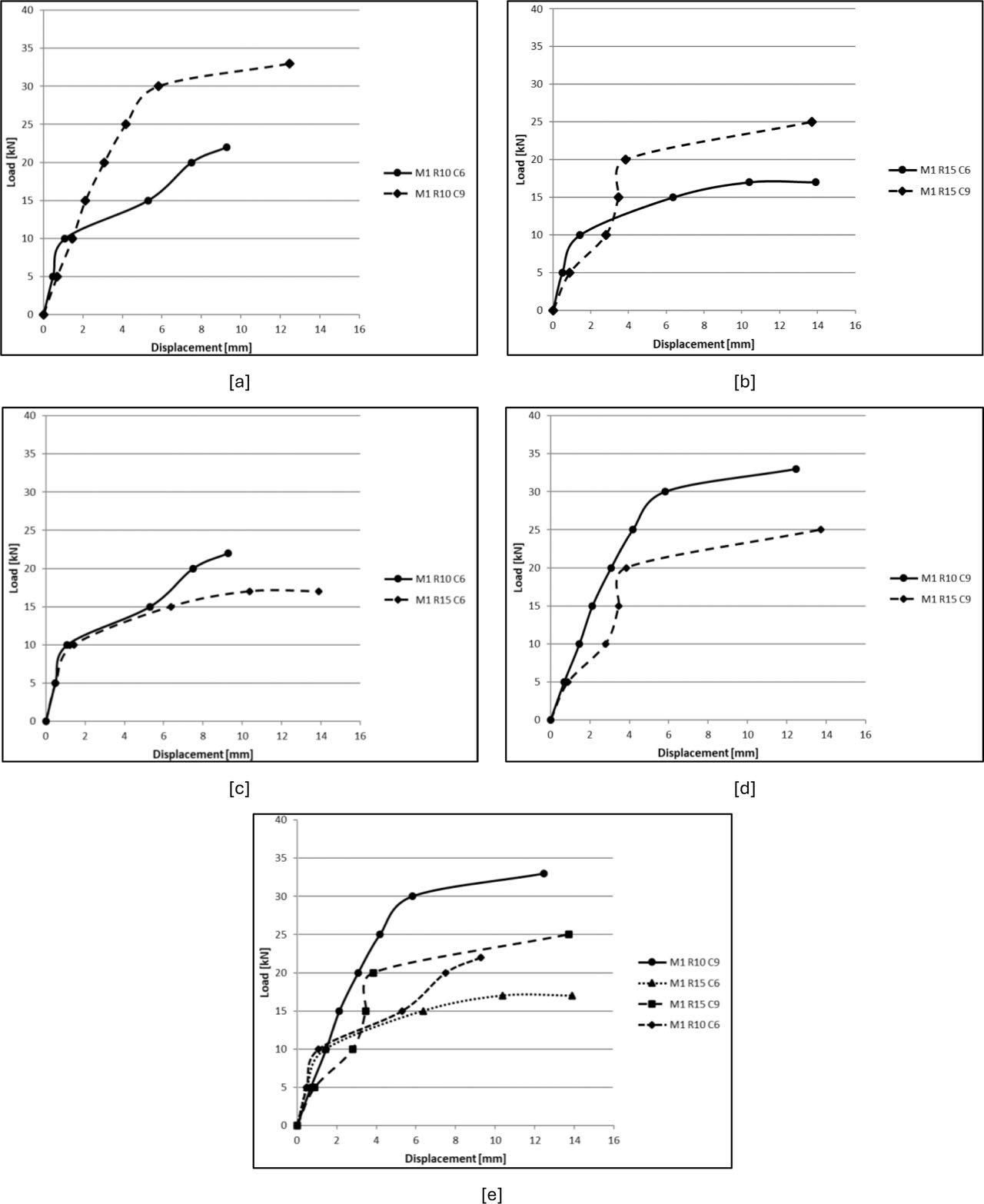
Figure 14:
Load–displacement curves for sandwich panel specimens [a] M1-R10-C6 and M1-R10-C9, [b] M1-R15-C6 and M1-R15-C9, [c]M1-R10-C6 and M1-R15-C6, [d] M1-R10-C9 and M1-R15-C9, [e] M1-R10-C9, M1-R15-C6, M1-R15-C9, and M1-R10-C6.
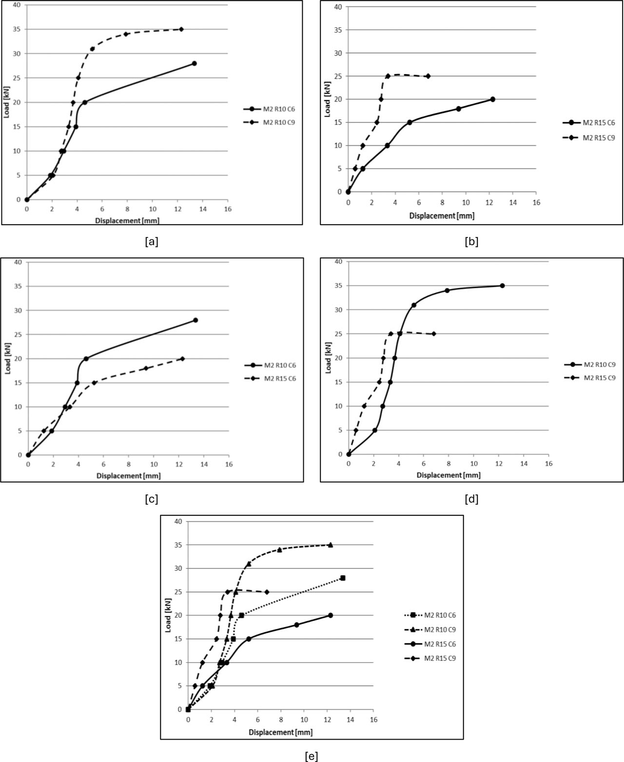
Figure 15:
Load–displacement curves for sandwich panel specimens [a] M2-R10-C6 and M2-R10-C9, [b] M2-R15-C6 and M2-R15-C9, [c] M2-R10-C6 and M2-R15-C6, [d] M2-R10-C9 and M2-R15-C9, [e] M2-R15-C6, M2-R15-C9, M2-R10-C9, and M2-R10-C6
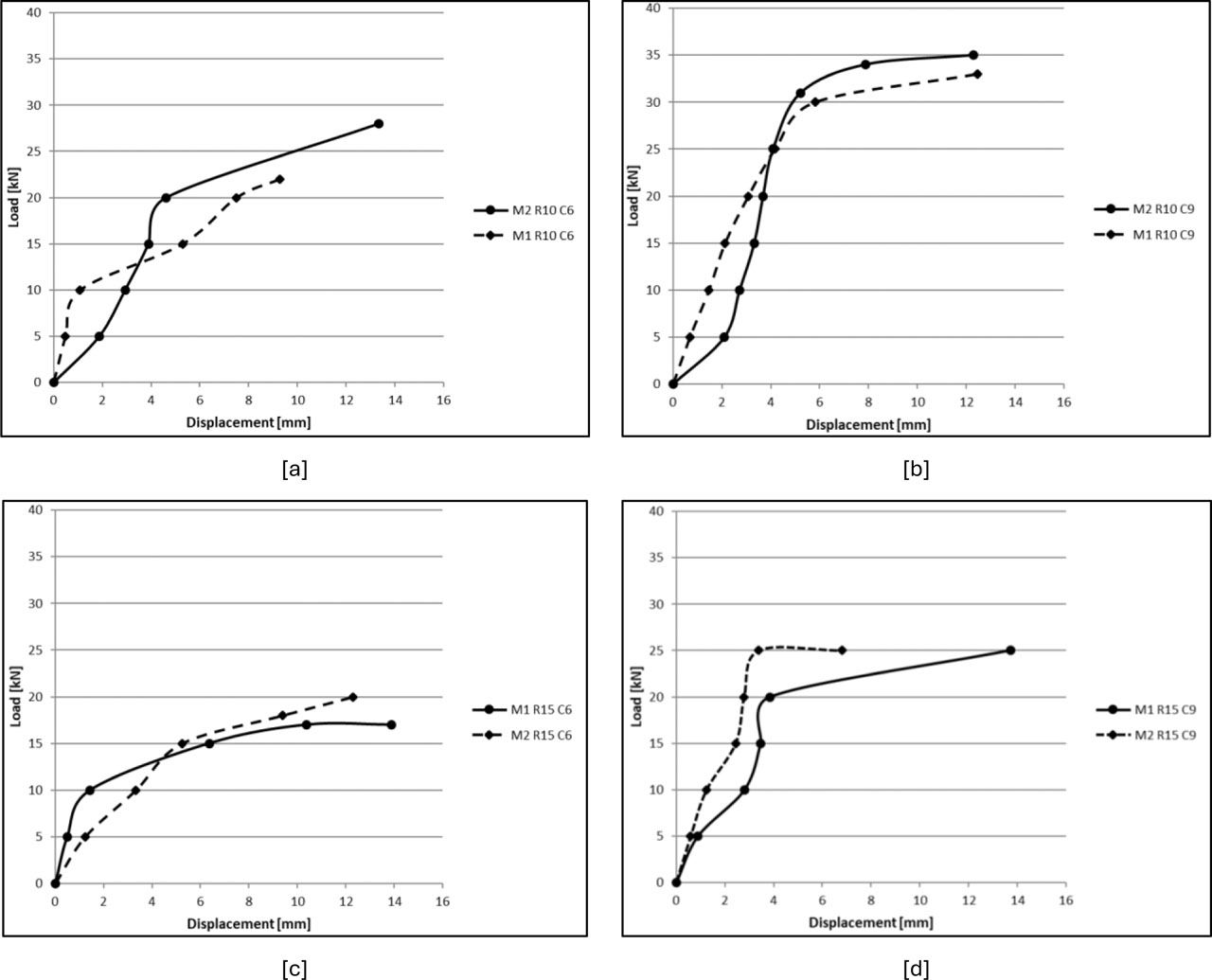
Figure 16:
Load–displacement curves for sandwich panel specimens for all specimens Mix 1 and Mix 2
4.2. Failure Modes Under Flexural Loads
The experiential failure modes of the tested sandwich panel specimens are concise in Table 5 and shown in Figure 17. During the four-point bending tests, the specimens displayed several failure features, containing initiation of flexural cracking within the foamed concrete core, face–core debonding between the steel face sheets and the core material, local outward bulging of the steel face sheet, and overall flexural bending deformation of the panel. Therefore, the final failure behaviour can be considered the result of the combined effects of core cracking/crushing, progressive debonding, and local steel face-sheet buckling, which together led to a reduction in stiffness and the development of the overall flexural deformation observed in the tested panels. Initial flexural cracks were experiential in several specimens once the applied load exceeded the elastic stage. These cracks usually initiated in the tensile region of the foamed concrete core within the continuous moment zone, as presented in Figure 17 [a]. The form of these cracks indicates that the tensile resistance of the foamed concrete core played a significant role in controlling the early flexural response of the sandwich panels. With further increase in load, visible debonding and separation between the steel face sheets and the foamed concrete core were detected in some specimens, as shown in Figure 17 [b]. This failure mode reflects a decrease in the composite interaction between the steel facings and the core material, resulting in local interface opening and a reduction in the overall bending stiffness of the panel. Furthermore, noticeable outward bulging of the steel face sheet was detected in certain specimens at higher load levels, as offered in Figure 17 [c]. This behaviour is related with local instability of the steel face sheet and specifies that the stiffness of the steel facing, and the rib spacing influenced the local structural response under flexural loading.
At progressive stages of loading, the tested specimens also showed overall flexural bending deformation, as presented in Figure 17 [d]. This global bending response occurred together with crack improvement and interface separation, and it reflects the combined influence of core cracking, loss of composite action, and reduced panel stiffness as failure improved.
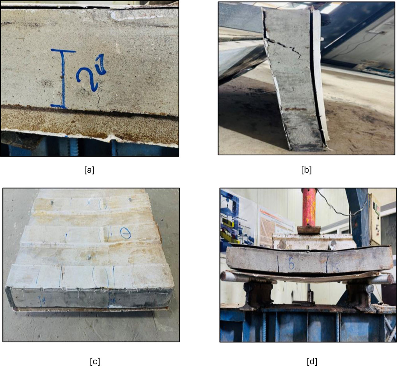
Figure 17:
Flexural failure characteristics of the tested sandwich panels, [a] initiation of flexural cracks in the foamed concrete core, [b] face-core debonding between the steel face sheet and foamed concrete core, [c] outward bulging of steel face sheet, [d] flexural bending of the sandwich panel specimen during testing
4.3. Axial Compression Test Results
The results gained for the axial compression tests are presented in Table 6 and Figures 18 to 20. The compression response exhibits a clear dependence on three interacting parameters: foam concrete compressive strength (Mix 1 ≈ 2.5 MPa and Mix 2 ≈ 4 MPa), rib spacing (R10 and R15), and number of connectors (C6 and C9). The mechanical response can be divided into three distinct stages:
Linear elastic composite action.
Stiffness degradation related with internal damage initiation.
Instability-controlled failure.
Through the initial loading stage, all specimens shown linear response, indicating actual stress transfer between the steel face sheets and the foam concrete core. In this stage, axial stiffness was mainly governed by the combined axial rigidity of the steel faces and the core. Specimens fabricated with Mix 2 exhibited a steeper initial slope, reflecting a higher actual modulus of the composite section the increased core compressive strength.
Table 6:
Axial compression test results
| Specimen ID | Ultimate load Pmax [kN] | Ultimate compressive stress σmax [MPa] | Vertical displacement Δv [mm] | Lateral displacement Δh [mm] | Failure mode |
|---|---|---|---|---|---|
| M1-R10-C6 | 156.24 | 0.434 | 9.50 | 0.76 | CC-DB |
| M1-R10-C9 | 265.61 | 0.739 | 13.64 | −7.7 | CR-DB |
| M1-R15-C6 | 429.66 | 1.19 | 11.87 | −3.77 | CC-SB-PDB |
| M1-R15-C9 | 429.66 | 1.19 | 9.40 | −3.39 | CC |
| M2-R10-C6 | 546.84 | 1.52 | 12.79 | 6.24 | CC-DB |
| M2-R10-C9 | 468.72 | 1.302 | 10.38 | −10.91 | GB |
| M2-R15-C6 | 156.24 | 0.434 | 9.50 | 0.76 | CC |
| M2-R15-C9 | 429.66 | 1.19 | 9.13 | 1.17 | SB |
Figure 18 [a] compares the uniaxial compression response of specimens M1-R10-C6 and M1-R10-C9. For the same rib spacing (R10), growing the connector number from 6 to 9 enhanced the ultimate load capacity and improved the overall structural response. Specifically, the ultimate compressive load improved by 64% when the number of connectors improved from 6 to 9. The specimen M1-R10-C9 continued a higher compressive load than M1-R10-C6, indicating that the added connectors improved the composite interaction between the steel face sheets and the foamed concrete core and enhanced the transfer of compressive forces through the section.
Figure 18 [b] shows the axial compression response of specimens M1-R15-C6 and M1-R15-C9. Although both specimens exhibited the same ultimate load, the additional connectors in C9 resulted in a slightly steeper load–deformation response, indicating a modest increase in stiffness. For the R15 configuration, six connectors may have already provided sufficient interaction between the steel plates and the core to develop the available compressive capacity. Therefore, increasing the number of connectors from six to nine did not produce a measurable increase in the ultimate load, which may have been governed by other factors such as the core or steel face-sheet capacity. This explains why both panels reached the same ultimate load of 429.66 kN, despite the difference in the number of connectors. The influence of rib spacing became clearer in Figure 18 [c], which shows the comparison between M1-R10-C6 and M1-R15-C6 while preserving a constant connector number of 6. The specimen M1-R15-C6 clearly exhibited superior compressive behaviour compared with M1-R10-C6, as reflected by its higher ultimate load. Specially, the ultimate compressive load of M1-R15-C6 was 174% higher than that of M1-R10-C6. This indicates that rib spacing had a pronounced effect on the axial compression response and that the R15 configuration providing a more favourable structural response under compression for the specimens with 6 connectors. A similar influence is shown in Figure 18 [d], where specimens M1-R10-C9 and M1-R15-C9 are compared at a continual connector number of 9. The specimen M1-R15-C9 again displayed a higher load-carrying capacity than M1-R10-C9, confirming that rib spacing stayed an important governing parameter even when the connector number was increased. Specially, the ultimate compressive load of M1-R15-C9 was 67% higher than that of M1-R10-C9. Consequently, the influence of rib spacing was not limited to the weaker connector configuration but stayed significant even in the better-connected panels. Figure 18 [e] presents a combined comparison of all Mix 1 specimens under axial compression, namely M1-R10-C6, M1-R10-C9, M1-R15-C6, and M1-R15-C9. The overall results show that the specimens with R15 rib spacing reached higher compressive resistance than the consistent R10 specimens, while increasing the connector number from 6 to 9 further improved the load capacity in both rib configurations. Among the tested configurations, M1-R15-C9 presented the highest compressive strength value, whereas M1-R10-C6 showed the lowest compressive resistance.
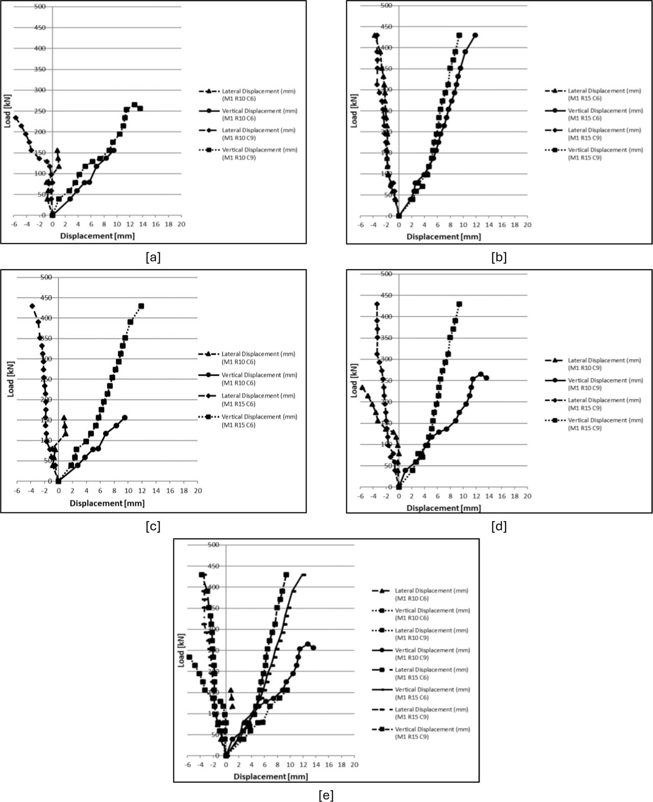
Figure 18:
Vertical and lateral load–displacement curves for axial compression specimens [a] M1-R10-C6 and M1-R10-C9, [b] M1-R15-C6 and M1-R15-C9, [c] M1-R10-C6 and M1-R15-C6, [d] M1-R10-C9 and M1-R15-C9, [e] M1-R10-C9, M1-R15-C6, M1-R15-C9, and M1-R10-C6
The axial compression response of the steel-faced foam concrete sandwich panels integrating the higher-strength core (Mix 2) is presented in Figure 19. Overall, the specimens displayed an initial linear response, corresponding to the elastic stage of the system, followed by advanced nonlinearity as the applied load increased. This deviancy from linearity reflects the gradual initiation of internal damage within the foam concrete core, the improvement of localized stress concentrations at the steel–core interface, and the onset of instability in the steel face sheets. Compared with the lower-strength core system (Mix 1), the Mix 2 panels usually sustained higher axial loads, approving that increased core compressive strength contributes significantly to improving the compression performance of the sandwich system.
Figure 19 [a] compares the compression behaviour of specimens M2-R10-C6 and M2-R10-C9. For the same rib spacing (R10), increasing the number of connectors from 6 to 9 did not improve the compressive capacity. In its place, the specimen M2-R10-C6 achieved a higher ultimate load than M2-R10-C9. Explicitly, the ultimate compressive load of M2-R10-C6 was 17% higher than that of M2-R10-C9. This result indicates that, under the R10 configuration, the stronger core shifted the governing mechanism away from the number of connectors alone and to the overall compatibility between the ribbed steel faces and the confined foam concrete core. In this case, the structural response submits that the R10 geometry with 6 connectors was adequate to assemble the core resistance more competently, whereas increasing the connector number did not interpret into a further gain in axial capacity. A different trend is detected in Figure 19 [b], which offerings the responses of specimens M2-R15-C6 and M2-R15-C9. Here, the specimen M2-R15-C9 clearly outperformed M2-R15-C6, display both higher load-carrying capacity and a lengthier vertical displacement response before failure. This exhibits that, for the R15 configuration, increasing the connector number meaningfully improved the axial compression performance. The result indicates that when the rib spacing becomes wider, extra connectors become more effective in strengthening the composite interaction between the steel facings and the stronger foam concrete core, thus improving force transfer and delaying instability. The role of rib spacing is additional clarified in Figure 19 [c], where specimens M2-R10-C6 and M2-R15-C6 are compared at a constant connector number of 6. The specimen M2-R10-C6 exhibited markedly higher compressive resistance than M2-R15-C6, indicating that, under the same number of connectors, the nearer rib spacing (R10) providing a more favourable axial compression response. Explicitly, the ultimate compressive load of M2-R10-C6 was 236% higher than that of M2-R15-C6. This behaviour suggests that the smaller rib spacing improved the restraint of the steel faces and enhanced the efficiency of stress transfer when the number of connectors was comparatively low. In contrast, Figure 19 [d] compares specimens M2-R10-C9 and M2-R15-C9 at a constant connector number of 9, where the conflicting trend is detected. Under this configuration, M2-R15-C9 presented higher load-carrying capacity than M2-R10-C9, representing that once the number of connectors was increased, the wider rib spacing (R15) became more useful to the compressive response. This finding exhibits that the effect of rib spacing in Mix 2 was not independent but powerfully conditioned by the connector arrangement. Therefore, the best compressive performance was reached when R15 was combined with 9 connectors, whereas under lower number of connectors, the R10 configuration proved more effectual. The combined comparison existing in Figure 19 [e], which contains M2-R10-C6, M2-R10-C9, M2-R15-C6, and M2-R15-C9, confirms that the compression behaviour of the Mix 2 panels was governed by a coupled interaction between rib spacing and connector number rather than by either parameter acting alone. Among the tested configurations, M2-R10-C6 and M2-R15-C9 appeared as the strongest, whereas M2-R15-C6 showed the weakest axial compression response. This obviously indicates that increasing number of connectors does not essentially guarantee enhanced compressive resistance unless it is combined with a rib geometry capable of competently stabilizing the steel faces and supporting the composite action of the system. Even though both mixes were influenced by connector number and rib spacing, the governing influence of these parameters differed between them. In Mix 1, the results exhibited a more consistent advantage for the R15 configuration, while increasing the number of connectors usually improved the axial resistance. In Mix 2, conversely, the response became more dependent on the interaction between rib spacing and connector arrangement, such that the best performance was not governed by a single parameter alone. Overall, the comparison confirms that increasing core strength meaningfully develops the axial behaviour of steel-faced foam concrete sandwich panels, though the final structural performance remains strongly reliant on the combined effects of rib geometry and connector configuration, as presented in Figure 20.
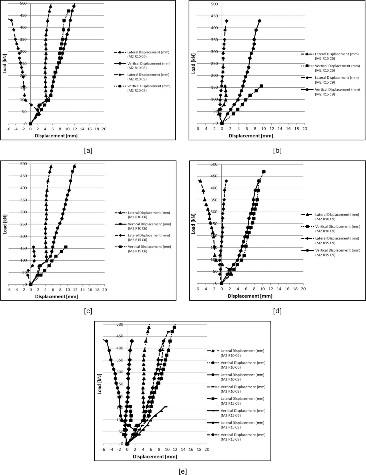
Figure 19:
Vertical and lateral load–displacement curves for axial compression specimens, [a] M2-R10-C6 and M2-R10-C9, [b] M2-R15-C6 and M2-R15-C9, [c] M2-R10-C6 and M2-R15-C6, [d] M2-R10-C9 and M2-R15-C9, [e] M2-R10-C6, M2-R15-C9, M2-R10-C9, and M2-R15-C6
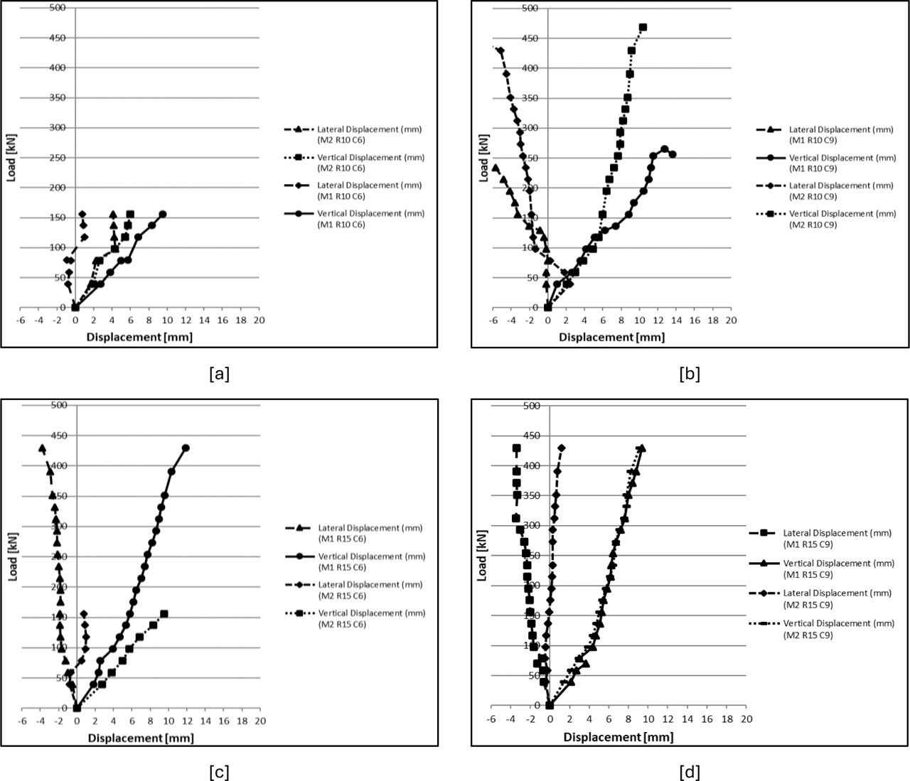
Figure 20:
Vertical and lateral load–displacement curves for axial compression for all specimens, Mix 1 and Mix 2
4.4. Failure Modes Under Axial Compression
The observed failure modes of the tested steel-faced foamed-concrete sandwich panel specimens under axial compression are shown in Figure 21. The compressive failure was governed by a combined mechanism including vertical cracking of the foamed concrete core, localized crushing nearby the loading zones, face–core debonding, and local buckling of the steel face sheets. Therefore, the ultimate axial compression failure resulted from the combined effects of core cracking and crushing, progressive debonding, and local face-sheet buckling, rather than from a single failure mechanism.
At the primary stages of loading, observable vertical cracks advanced within the foamed concrete core, principally near the loaded regions, as presented in Figure 21 [a]. These cracks transmitted along the panel height with increasing compressive load, representing progressive internal harm and stress rearrangement within the core material. In numerous specimens, cracking was accompanied by local crushing of the core in the compression zone, principally near the loading region, where the compressive stresses were focused. As loading progressed, obvious debonding and separation between the steel face sheets and the foamed concrete core were detected, together with a vertical crack covering through the core, as showed in Figure 21 [b]. This separation shows a gradual loss of composite interaction between the steel facings and the core, principally along the panel edges and near interface regions exposed to high stress concentrations. In adding, the steel face sheets showed clear local outward buckling and bulging between adjacent ribs, as presented in Figure 21 [c]. This behaviour reflects the local instability of the thin ribbed steel facings after the restraint providing by the foamed concrete core was reduced because of cracking and interface debonding. Overall, the final axial compression failure of the tested panels was governed by the interaction of core cracking, localized crushing, interface separation, and local face buckling. After eliminating the steel face sheets from selected failed specimens, the internal condition of the foamed concrete core exposed extensive cracking and local crushing, confirming the severity of internal core damage under axial compression, as shown in Figure 21 [d].
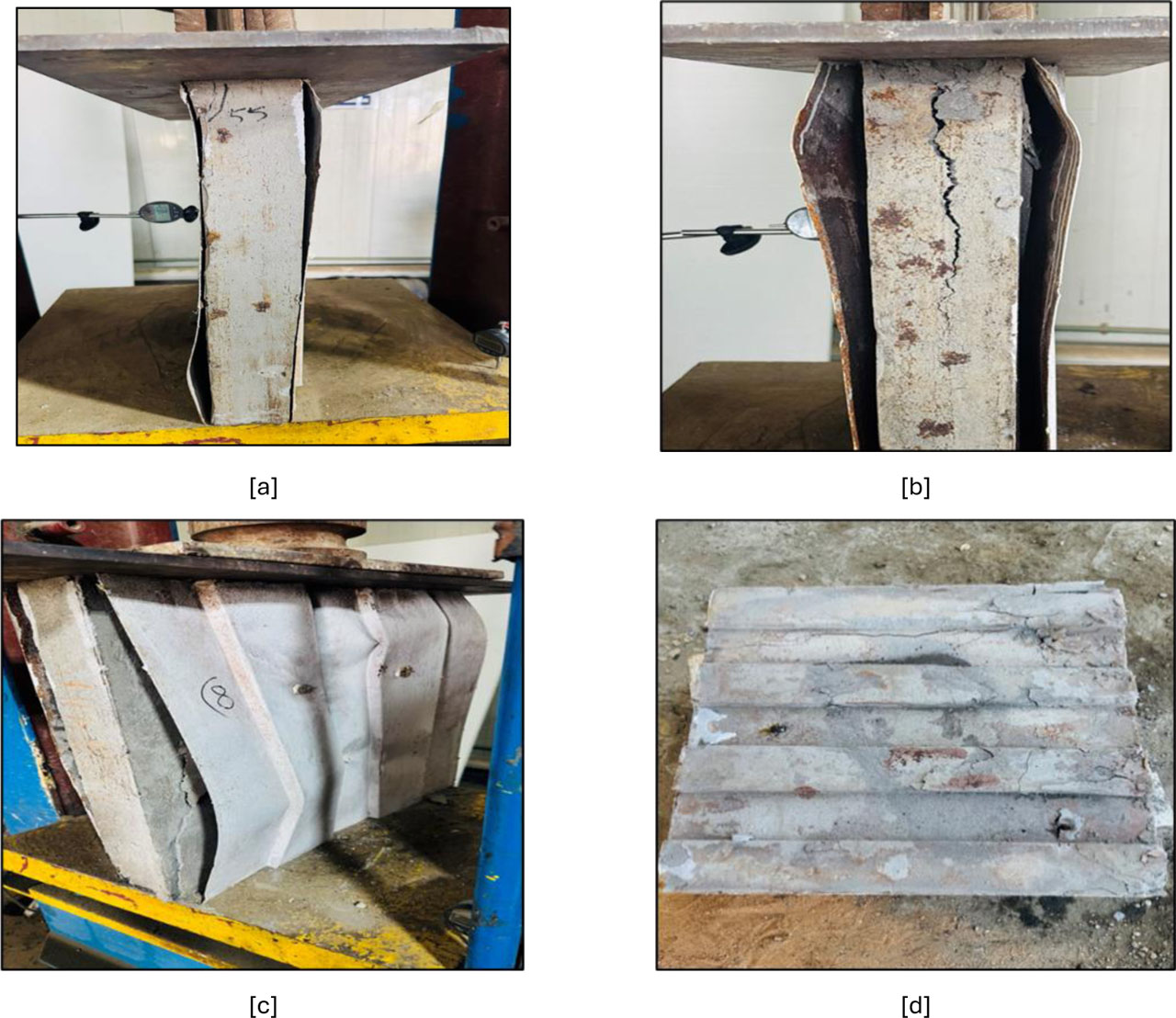
Figure 21:
Failure modes of the tested sandwich panels under axial compression, [a] core cracking, [b] face–core debonding, [c] local buckling of the steel face sheet, [d] internal core damage after removing the steel face sheets
5. Conclusion
This study experimentally investigated the flexural and axial compression behaviour of steel-faced foamed-concrete sandwich panels incorporating different rib spacings and connector arrangements. Based on the experimental results obtained within the investigated configurations, the following conclusions can be drawn:
The compressive strength of the foamed concrete core significantly influenced the structural performance of the sandwich panels. The higher-strength foamed concrete core improved both the load-carrying capacity and stiffness under flexural and axial compression loading, demonstrating the important role of the core material in the overall structural response.
The structural response of the panels was governed by the development of composite action between the steel face sheets and the foamed concrete core; Mechanical shear connectors enhanced this interaction by improving load transfer between the steel face sheets and the foamed concrete core.
The relative influence of connector number and rib spacing depended on the mechanical properties of the foamed concrete core. For the lower-strength mix (Mix 1), the number of connectors had a greater influence on the structural response than the rib spacing, indicating that the efficiency of the mechanical connectors played a dominant role in improving composite interaction and load transfer.
For the higher-strength mix (Mix 2), rib spacing had a more pronounced effect on panel stiffness and load-carrying capacity than the connector number, indicating that the structural response became more sensitive to the rib configuration when the higher –strength foamed concrete core was used.
Within the investigated configurations, panels with R10 rib spacing generally exhibited higher stiffness and improved structural performance than those with R15. However, the observed influence of rib spacing depended on the foamed concrete strength and connector arrangement, indicating that rib spacing should be considered together with these parameters rather than as an independent design factor.
Overall, the results demonstrate that achieving effective composite action through an appropriate combination of core strength, rib spacing, and connector arrangement can improve the structural efficiency of steel-faced foamed concrete sandwich panels for lightweight building applications within the investigated configurations.
Notes
[7] Contributed by Author Contributions
H.A.H. contributed to design the study, performed the data analysis, performed the formal analysis, the development of the evaluation methodology and statistical analysis, contributed to data curation, interpretation of the results, and drafting of the manuscript. A.Al. contributed to design the study, resources, supervision, assisted with visualization and preparation of figures and tables, and critical revision of the manuscript. All authors critically reviewed and approved the final version of the manuscript and agreed to be accountable for all aspects of the work.