

1. Introduction
Rigid pavements constructed using Portland cement concrete (PCC) are commonly used in transportation applications, which include parking areas, airport runways, and highways. Nevertheless, typical concrete's poor tensile strength and inherent brittleness can cause early cracking and collapse, especially in areas of earthquake-prone, active regions. It has become crucial to use high-performance concrete (HPC) with fiber reinforcement to get beyond these restrictions. Steel fibers significantly improve ductile performance features, offer improved control over typical fracture development and propagation, and boost energy absorption capacity whenever added to concrete matrices. The use of Fiber-reinforced concrete (FRC) was the focus of previous research on earthquake-resistant building materials. In many structural applications, high-performance fiber-reinforced concrete (HPFRC) showed excellent mechanical performance and outstanding seismic performance versus conventional reinforced concrete. When used on rigid pavements, such materials can significantly improve resistance to environmental stresses and dynamic loads.
The increasing requirement for pavement systems that can handle impacts from heavy vehicle loads and seismic impacts has encouraged research on the experimental performance of HPC with fiber reinforcement under cyclical loading conditions. Superior strength, improved permeability, and enhanced impermeability versus ordinary concrete are characteristics associated with high-performance concrete (BARROS et al., 2025). Additionally, the tensile strength and post-cracking ductility are made achievable by fiber reinforcement (steel, synthetic, or natural). HPFRC can sustain cyclical loads without catastrophic failure because of its extremely strong compressive strengths as well as efficient fiber bridging processes (KANG et al., 2025). The effects of the addition of steel fiber on the mechanical properties of rigid paving pavements have been extensively researched. Steel fiber reinforcement at 1%, 3%, and 5% of volume has been shown in multiple experiments to greatly enhance compressive, tensile, and flexural stiffness (TAHER et al., 2024). At 18 days of curing, the flexural strength can be raised by up to 60% by adding 5% steel fiber. Also, it has been studied how using hybrid fiber systems made of steel and carbon fibers or other blends may decrease costs while improving performance (ALQUBAYSI et al., 2025). Laboratory testing has been used to accurately define the performance of fiber-reinforced concrete under seismic loads. As compared to normal concrete, high-performance fiber-reinforced concrete beam-column joints under cyclic loading have shown significant improvements in the load-carrying capacity and energy absorption performance (ALQUBAYSI et al., 2025). While structural elements are being tested for cyclic loads, the use of varied aspect ratios and conventional steel fiber content enhances dimensional stability, integrity, and ductility. For pavement structures that must sustain dynamic pressures and deformations caused by earthquakes, these qualities are necessary (KUMAR et al., 2025). With the aim of overcoming brittleness and producing better resistance to cracking, Fiber-Reinforced Concrete (FRC) combines spatially statically uniformly distributed fibers in the concrete matrix. Steel, polypropylene, glass, basalt, and natural fibers—all of which offer specific benefits to the composite structure may be employed to achieve this (SINGH et al., 2025). Steel fibers are a common fiber type because of its distinctive characteristics, which include a 25%–50% increase in tensile strength, a 75% reduction in crack formation, and an enhancement in tensile load ability and energy absorption capacity (BARROS et al., 2025). Glass fibers produce great chemical resistance and extremely durable performance in severe conditions, while polypropylene fibers master plastic shrinkage control and a long lifespan. Through reversing synergistic impacts, hybrid fiber systems far exceed single-fiber reinforcing techniques. A hybrid composite with the advantageous mix of strength, ductility, and economy develops when steel fibers are combined with synthetic equivalents like polypropylene, basalt, or glass fibers (KANG et al., 2025).
According to previous studies, fiber doses (volume fraction), which are usually between 0.5% and 2.0%, are customized depending on the application and mechanical performance demanded (PANDU et al., 2020). Fiber-reinforced HPC combines highly advanced additives, such as micro silica and superplasticizers, to improve workability and strength development and maintain low permeability. To stand up to growing traffic loads and ambient/environmental stresses, rigid pavements, which are usually made up of Portland cement concrete, demand stronger mechanical qualities and durability. In pavement design, fiber-reinforced concrete has become increasingly popular, especially in seismic applications where pavements must withstand both vehicle stress and seismic pressures (SINGH et al., 2025). Better fatigue resistance, additional time in life, and decreased pavement maintenance are only a handful of the performance demands that fiber-reinforced concrete presents. The qualities of fiber-reinforced concrete pavements, which can achieve compressive strengths in the range of 65–89 MPa and flexural parameters of more than 6–11 MPa, commonly meet near extreme heavy-traffic standards, have been the subject of much research in recent years (KUMAR et al., 2025). Using hybrid systems, which blend steel and polypropylene fibres, provides synergistic advantages that are superior to what might come from using only one type of fibre. This hybridisation technique makes use of the advantages of each material: polypropylene fibres offer improved long-term durability and early-age crack reduction, whereas steel fibres serve as the primary reinforcement and enhance strength growth (YASSIN et al., 2024). When compared to control non-fibrous composites, optimum hybrid combinations are known to boost tensile strength by 40–50% and toughness indices by up to 300% (ZHANG et al., 2026).
2. Methodology
2.1. Material Preparation and Specimen Design
This laboratory study evaluated rigid pavement slabs constructed from high-performance concrete with steel, polypropylene, and hybrid fiber reinforcement
A. Cement
Sulphate-resistant Portland cement (Type I), produced by the Iraqi Al-Mass Group, was used in this study. Cement's physical and chemical characteristics, as shown in Table .1, satisfy ASTM C150/C150M specifications. Materials and Procedures
Table 1:
Cement Properties
| Oxides composition | Content [%] | ASTM C150-16 [%] | IQS No.5 / 2019 [%] |
|---|---|---|---|
| CaO | 60.77 | - | |
| SiO2 | 21.80 | - | |
| Fe2O3 | 4.80 | 6.0 (max.) | |
| Al2O3 | 3.85 | 6.0 (max.) | |
| MgO | 2.26 | 6.0 (max.) | 5.0 (max.) |
| SO3 | 2.30 | 3.0 (max.) | 2.5 (max.) |
| C3A | 2.09 | - | 3.5 (max.) |
| Loss on Ignition, L.O.I | 2.44 | 3.5 (max.) | 4.0 (max.) |
| Lime Saturation Factor, L.S.F | 0.86 | - | (1.02-0.66) |
| Insoluble Residue | 1.43 | 1.5 (max.) | 1.5 (max.) |
B. Aggregates
The Al-Nibaie quarry, which is situated northwest of Baghdad, Iraq, provided the natural sand (fine aggregate) and crushed gravel (coarse aggregate), both of which are composed of quartz-based minerals. AASHTO M 43 and AASHTO T-27 were used to quantify and grade these aggregates, with a maximum size of 4.75 mm for natural sand and 12.5 mm for crushed gravel.
C. Super plasticizing and Water
In keeping with Iraqi Specification No. 417/2001, standard potable water was chosen for concrete mixing and curing. With a chloride concentration of 64.3 mg/L, it was sufficiently below the 200 mg/L standard. Furthermore, the pH and sulphate concentration were found to be within the permissible levels (pH: 6.5–8.5; sulphate: < 200 mg/L) at 7.1 and 114.3 mg/L, respectively. Superplasticizers are acknowledged as the most efficient agents for lowering the water-to-cement ratio, which is important in producing high-performance concrete, although numerous contemporary admixtures have been produced for the manufacturing of concrete. Consequently, in this research, using Sika’s “ViscoCrete” polycarboxylate polymer technology (third generation), Sika ViscoCrete-171 Precast is a high-range water-reducing, superplasticizing, and hardening accelerator for concrete and mortar.
D. Silica Fume
Silica fume is a pozzolanic material employed as filler to enhance the amount of fine components in the mixture and improve its cohesion and segregation resistance (SCC). CONMIX MegaAdd MS (D)
e. Fibers
As shown in Figure 1, two types of fibers have been added to the concrete mixes in three different configurations: exclusively steel fibers, exclusively polypropylene fibers, and a hybrid combination of both steel and polypropylene fibers. Their capacity to improve the pavement's mechanical qualities and their compatibility with the concrete matrix were important in their selection. Table 2 provides specific details on these fibers.
Table 2:
Properties of steel and polypropylene Fibers
| Properties | Steel fiber | Polypropylene fiber |
|---|---|---|
| Appearance | Straight, rounded steel fiber | Straight white embossed fibers |
| Material | Low-carbon steel wire, copper-coated | - |
| Diameter, [mm] | 0.2 | 0.22 |
| Length, [mm] | 12 | 12 |
| Tensile strength, [MPa] | 2850 | 465 |
| Elastic modulus, [GPa] | 200 | 7.5 |
| Density, [kg/m3] | 7800 | 0.91 |
| Aspect ratio | 60 | 60 |
Two types of mixtures used in this study, ACI 211.1, were promptly followed in the design of the concrete mixture. A control mix without fiber, and high performance concrete with five mixtures with different amount and types of fiber, a single-fiber mix with 1% steel fiber, a single-fiber mix with 1% polypropylene fiber, and three hybrid mixes with a total fiber content of 1% that included 0.75% steel/0.25% polypropylene fiber, 0.25% steel/0.75% polypropylene fiber, and 0.5% steel/0.5% polypropylene fiber. Because the increased fiber surface area could disturb the homogeneity of the mix, adding fibers required adjusting the amount of superplasticizer to preserve workability. The different mixes, their fiber amounts, and the matching superplasticizer dosages and mix proportions are listed in Table 3. After testing, the proportion of hybrid fiber (0.25% steel, 0.75% polypropylene) was selected. These proportions were employed to leverage the durability characteristics of the steel fibers and to minimize expenses. Polypropylene fibers were used to enhance corrosion characteristics, offering a broad dispersion within the mixture and aiding in the sealing of hairline cracks to inhibit their propagation.
Table 3:
Concrete mixture proportions for NC and HPC mixtures
| concrete | Cement [kg/m3] | Fine aggregate [kg/m3] | Coarse aggregate [kg/m3] | Silica fume [kg/m3] | Fiber in [%] of volume fraction | water | HRWR [%] | Ƒc̀ [MPa] |
|---|---|---|---|---|---|---|---|---|
| NC | 400 | 640 | 932 | - | - | 180 | - | 35 |
| HPCSF | 360 | 720 | 1050 | 90 | 1% | 157.5 | 0.8% | 70.6 |
| HPCPPF | 360 | 720 | 1050 | 90 | 1% | 157.5 | 1.2% | 68.2 |
| HPCHF | 360 | 720 | 1050 | 90 | 0.25%steel/0.75% polypropylene | 157.5 | 1.2% | 70.1 |
2.2. Mixing procedure in case of using steel fiber
2.2.1. The following was the order of mixing:
To make sure the fine SF powder was evenly distributed among the cement particles, the required amounts of cement and silica fume were first introduced to the mixer in a dry condition and stirred for five minutes. To create a uniformly distributed mixture, fine sand was then added to the mixer in a dry state and stirred for three minutes at a low speed. Half of the mixing water was added to the mixer with continuous blending for 3 minutes. The determined quantity of HRWRA was dissolved in the other half of the mixing water before starting the mixing process. This quantity was divided into four parts. Part one was added to the other constituents in the mixer after the previous step, mixing for about 5 minutes or until forming small glossy balls of the paste. Thereafter, the second part was added with continuous mixing for another 5 minutes. At this stage, large glossy balls of paste were formed. Then, the third part was added with progressive mixing for about 3 minutes or until the paste became a slurry. mixing for about 4 minutes. To guarantee adequate fiber dispersion, the designated amount of steel fibers was gradually added to the mixer and mixed continuously for four to six minutes. Lastly, the fourth component of water-dissolved HRWRA was added, with constant
2.3. Mixing Procedure in Case of Using Polypropylene Fibers:
The mixing sequence was as follows:
First, the mixer was filled with the calculated amount of dry sand.
The polypropylene fibres were then gradually added and continuously mixed until the friction with the moving sand particles caused all of the fibers to separate into their hair filaments. The duration varied from 10 to 15 minutes, depending on the amount of polypropylene fibres. Cement and silica fume were combined for approximately three minutes. For roughly five to six minutes, this premixed binder was gradually added to the mixer while being continuously mixed. To prevent the mixture from overheating, half of the water was mixed with cold water and mixed continuously for three minutes. The premixed HRWRA was added in the same order as the steel fibres, with the other half being mixing water. A homogeneous mud paste was the final result. It took between 30 and 40 minutes to finish one batch of the mixture. As a result, the mixing time needed for polypropylene fibres was greater than that needed for steel fibres. These procedures are also applicable to the hybrid mixture.
2.4. Preparation and Curing of Specimens
To replicate a standard highway pavement section, concrete specimens were made in rigid pavement slab molds measuring 1000 mm* 800 mm *50 mm. After an average period of 24 hours at room temperature (23°C ± 2°C), the specimens were demoulded. For carrying out seismic shaking table testing, eighteen specimens (three for each mix) were constructed. According to ASTM C192, the specimens were cured for 28 days at 23°C in a fog room.
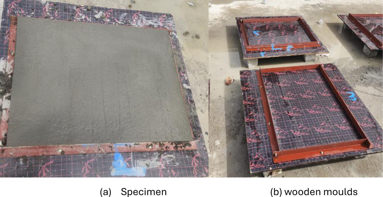
Figure 1:
Preparation for moulds and specimen: (a) specimen; (b) wooden moulds
3. Procedure to perform experimental tests and construction under seismic conditions
3.1. Designing the Shaking Table Test
Whenever constructions shift from their foundations due to a seismic loading of the scale shaking table in the earthquake engineering laboratory, rigid pavement slabs, even small horizontal motions, can cause severe structural failure, as shown in Figure 2. With a peak ground acceleration (PGA) of 0.38 g (about 341.6 cm/s2), the loading protocol simulated a moderate earthquake that is typical of design parameters in many seismically active areas. Earthquakes from El Centro were caused. The shaking table is a highly advanced seismic simulation platform designed to produce X and Y-directional horizontal ground motions. True two-degree-of-freedom (2-DOF) control is made available by this technology, which sets it apart from conventional uniaxial tables and allows for either independent or coordinated seismic excitations along orthogonal axes. Notably, the shaking table was fully developed, built, and put together in Iraq, demonstrating the sophisticated structural testing capabilities of local engineers. LabVIEW-programmed input ground motion commands are handled by an NI USB-DAQ system before being sent to Delta drives (ASD-A2-4543-M). To keep accuracy against target waveforms, real-time sensor data—such as acceleration and displacement—is continuously provided back into the control loop. For calibration, alignment, and real-time safety control, the system's automatic and manual modes provide operating flexibility. Testing under both observed and simulated seismic occurrences is made possible by the shaking table's support for medium- to large-scale structural models. When scaled suitably for physical model testing, the system has successfully reproduced real earthquake records, including the El-Centro 1940 catastrophe. As a result, the shaking table is a key component of this research and offers a considerable breakthrough in local seismic testing capabilities.
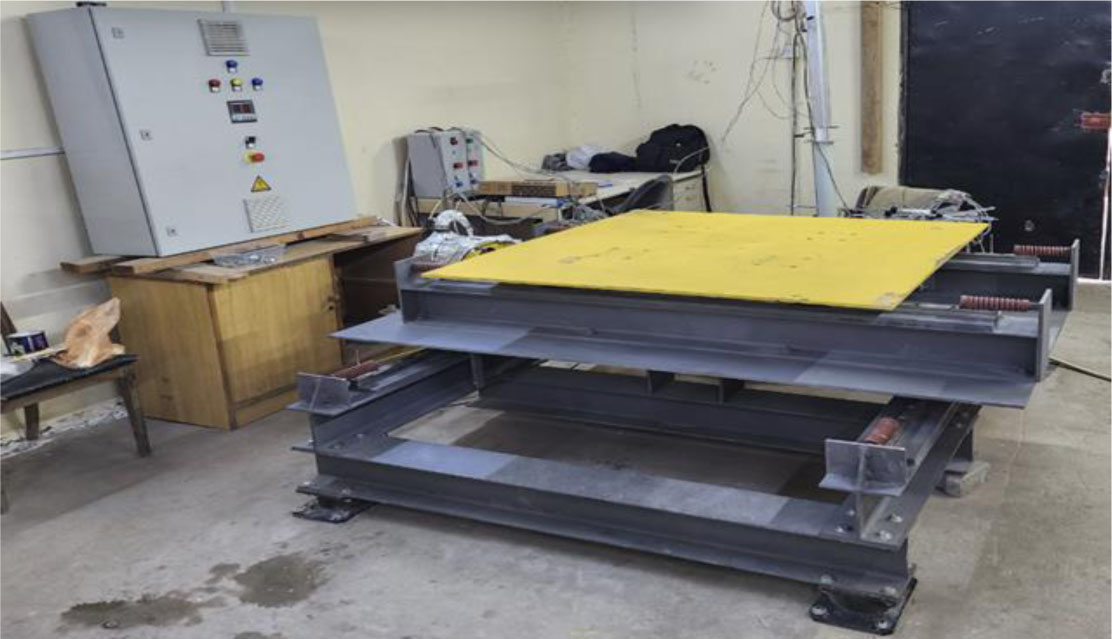
Figure 2:
Shaking table
3.2. Instrumentation and Loading Protocol
LVDT Sensors (X, Y Axes SDVB20) As shown in the figure 3, linear variable differential transformers use a 100 mm stroke and a resolution of less than 0.1 μm to monitor the relative displacement between structural nodes. KTR Displacement Sensors (X, Y Axes, KTR-300). For monitoring movements in smaller model designs, tiny analogue displacement sensors with a 300 mm stroke and ±0.05% linearity are utilized. Accelerometers (X, Y Axes, ADXL335). To evaluate localized dynamic response, such as rocking and interstory acceleration, additional accelerometers have been put directly on the specimen. One of the more advanced tools to evaluate strain fluctuations is a strain gauge. Two different kinds of uniaxial electrical resistance strain gauges were employed in this investigation. As seen in the figure, TML Tokyo Sokki Kenkyojo Company in Japan produced these strain gauges. A specially created LabVIEW virtual instrument (VI) for the shaking table platform is used to control and track the experimental system. Through this interface, real-time sensor data can be acquired, acceleration and displacement command files can be integrated, and system reactions along the X and Y axes may be visualized.
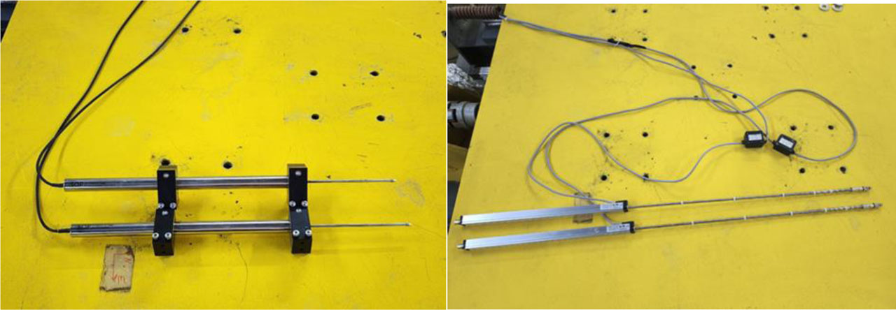
Figure 3:
LVDT and KTR
4. Data Collection
The experimental setup is shown in Figure 4. The specimens were placed on a soil base composed of a subbase with two servo motors to simulate the (X-Y) direction seismic loading in both directions, while Linear Variable Displacement Transducers (LVDTs) positioned as shown in Figure 4.
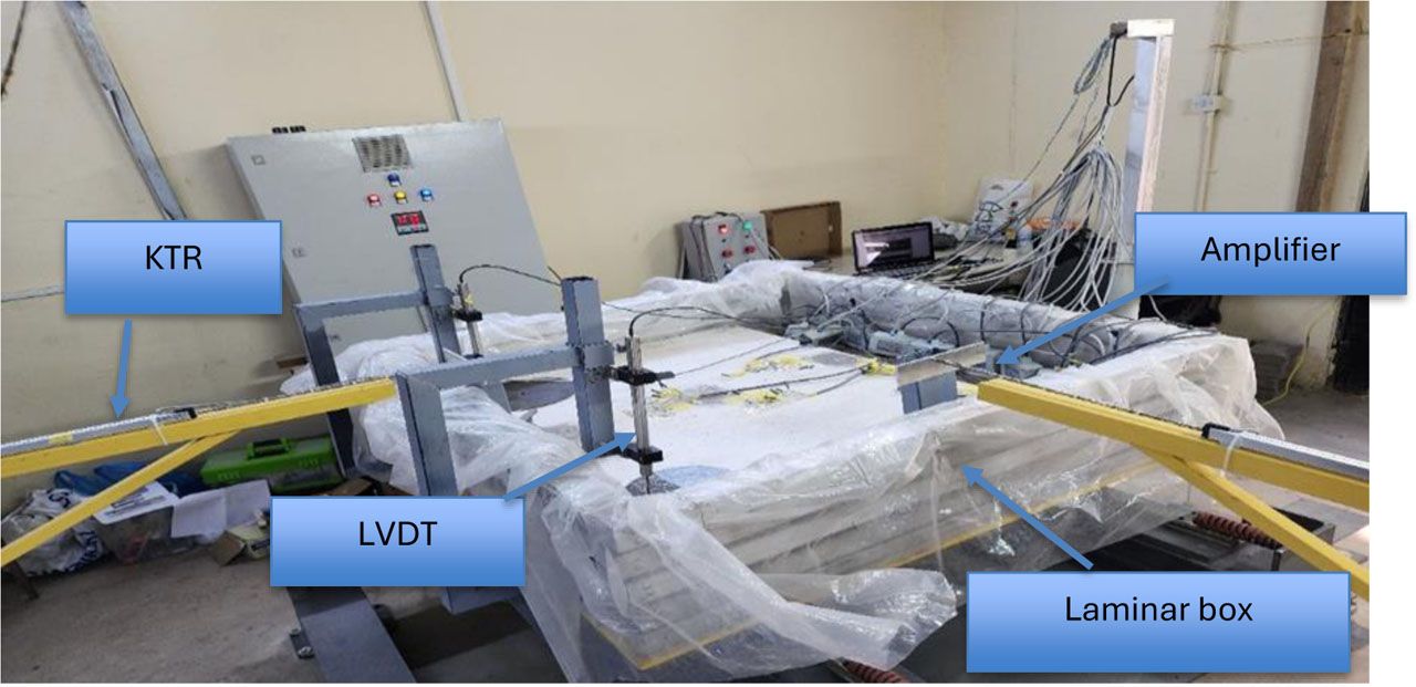
Figure 4:
Test set-up and details of the instrumentations
The subbase layer was compacted at distances of 15 cm until reaching maximum density and maintaining a level surface. The concrete slab was thereafter put above the compacted soil layer. The laminar shear box was set up after its fixing on the shaking table platform, and all sensors were installed. The sensors were eventually placed on the concrete slab in vibration-sensitive locations, including the corner, middle, and edge of the slab. Upon checking the linkage of all sensors to the data acquisition, the device was checked for calibration before performing the application of the El Centro earthquake in two directions. Set LVDTs (Linear Variable Differential Transformers) upward to locate any “movement” or rising of the slab edges and horizontally to measure lateral displacement, as shown in Figure 5.
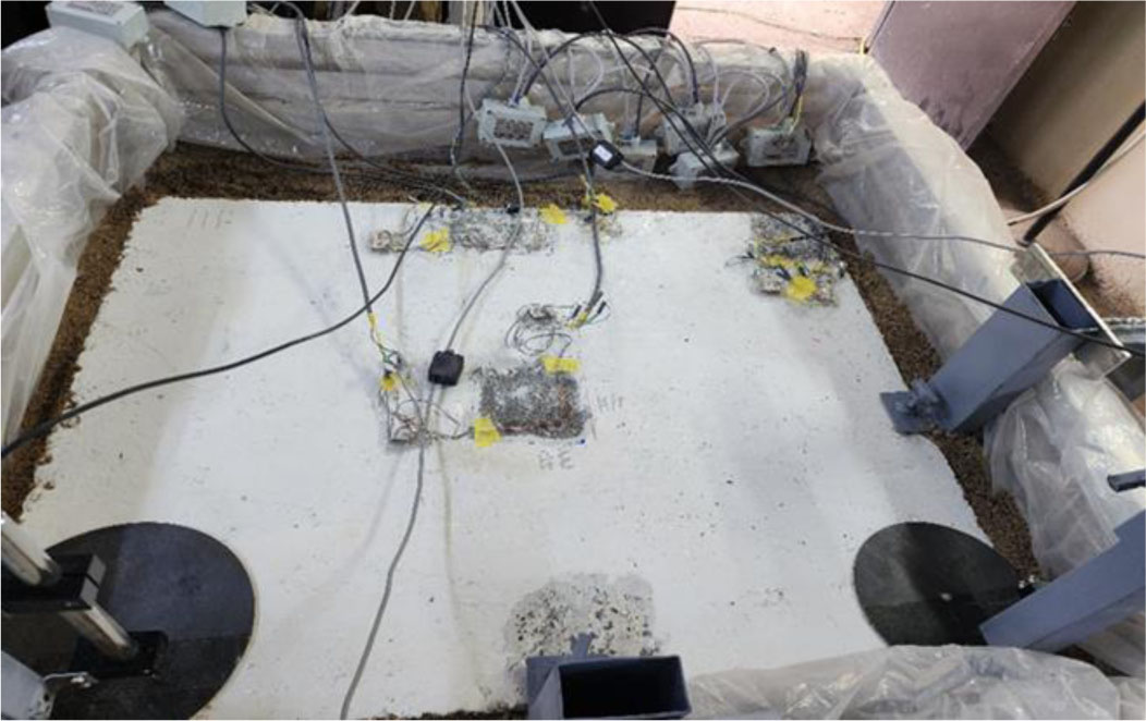
Figure 5:
Concrete slab in a laminar box on a shaking table
5. Results
The Shaking Table test results demonstrate that the four samples studied, reference concrete, steel fibers, polypropylene fiber-reinforced concrete, and hybrid reinforcement, have considerably different displacement-time history characteristics. Peak displacement measurements recorded during the first ten seconds of testing show that all samples responded instantly to the first seismic shocks. However, compared to the reference sample, which took longer than the others to calm down after reaching the tremor peak, the fiber-reinforced samples were able to disperse significantly more vibrations. Material Steel Fiber (SF) Efficiency: As it came to reducing relative displacement, the SF sample had the most significant structural performance. When iron fibers were the stiffest, they increased slab restriction of movement and more efficiently controlled the response around zero-baseline than other samples. This is all over vibration cycles, the iron fibers form a bridge to stop tiny cracks from developing bigger. PPF & HF (robust & Hybrid Response): High frequency oscillations in the sample under robust response conditions proved clearly that fibers played a part in absorbing impact energy, though they weren't as brittle as the iron fibers. In contrast, the hybrid sample hf. Because it reduced maximum displacement and permitted constant tension transfer through the slab (as seen by the proximity between LVDTs nos. 1 & 2), the hf's performance was substantially even. Residual Displacement: As stated before, it is important to determine the possibility that the dynamic activity of a seismic motion has left any permanent deformation in the structures being investigated. As a result, the processed data from the SF sample were studied in the same way, and nearly no residual displacement occurred after dynamic loading stopped. It verifies that when HPC rigid pavements with these values reach this level of ground acceleration, they stay framed within an elastic range without developing significant permanent deformations. As shown in Figure 6.
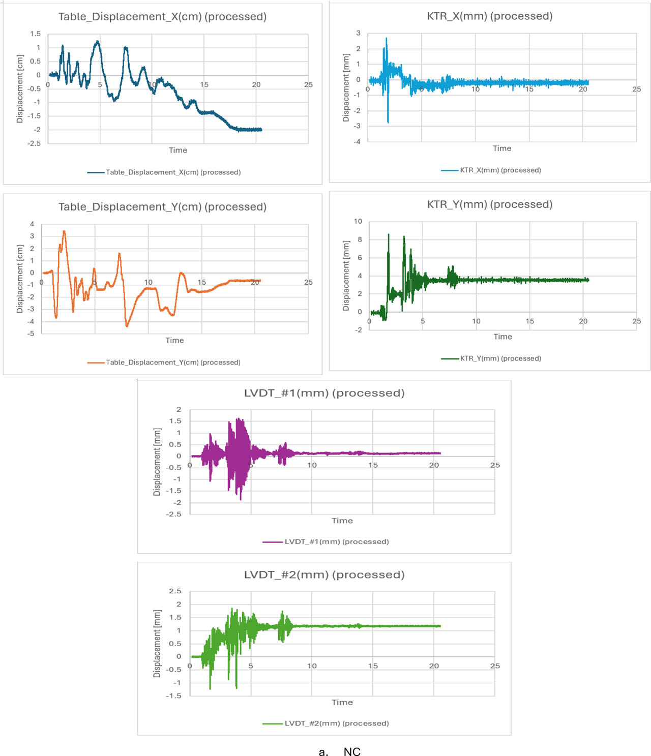
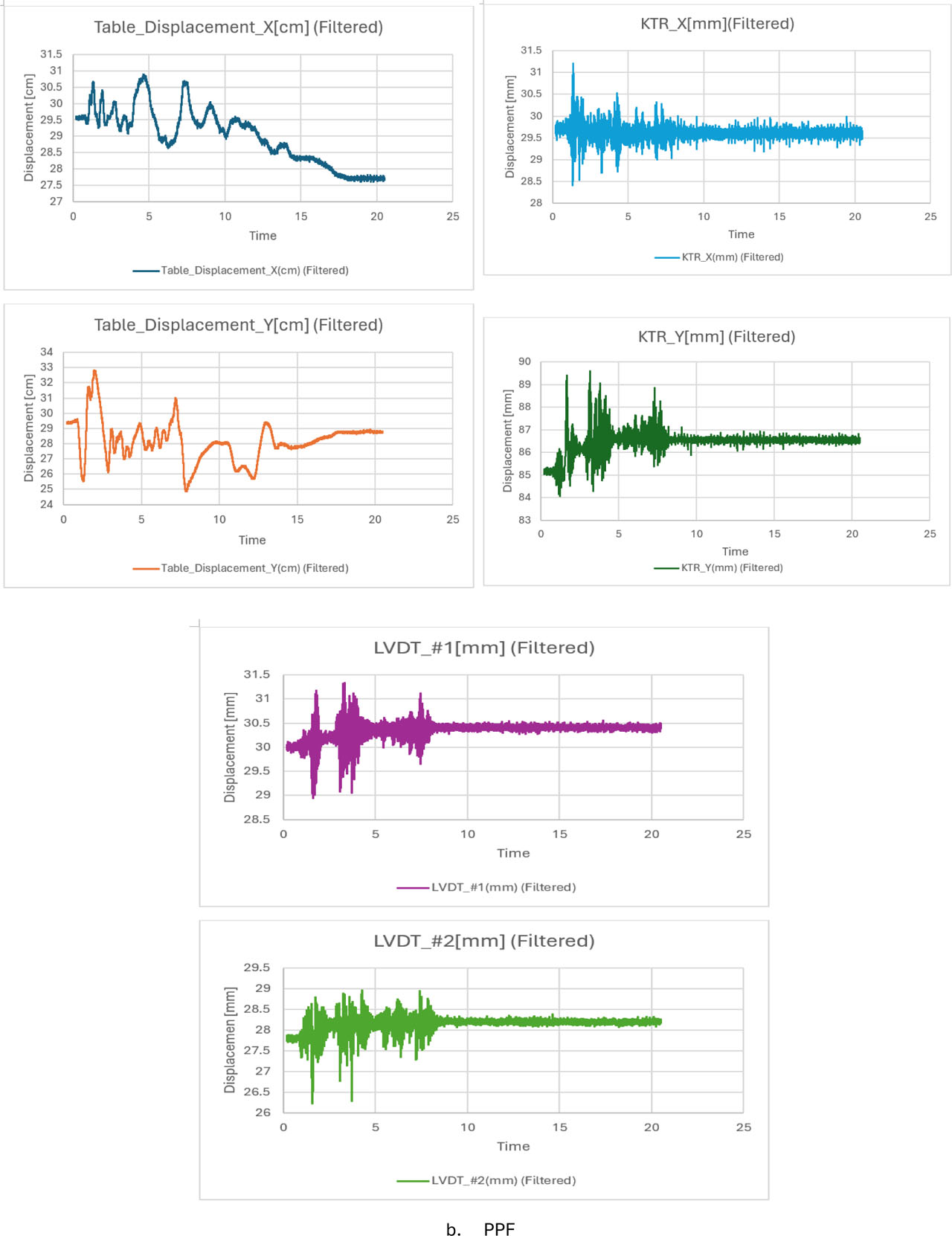
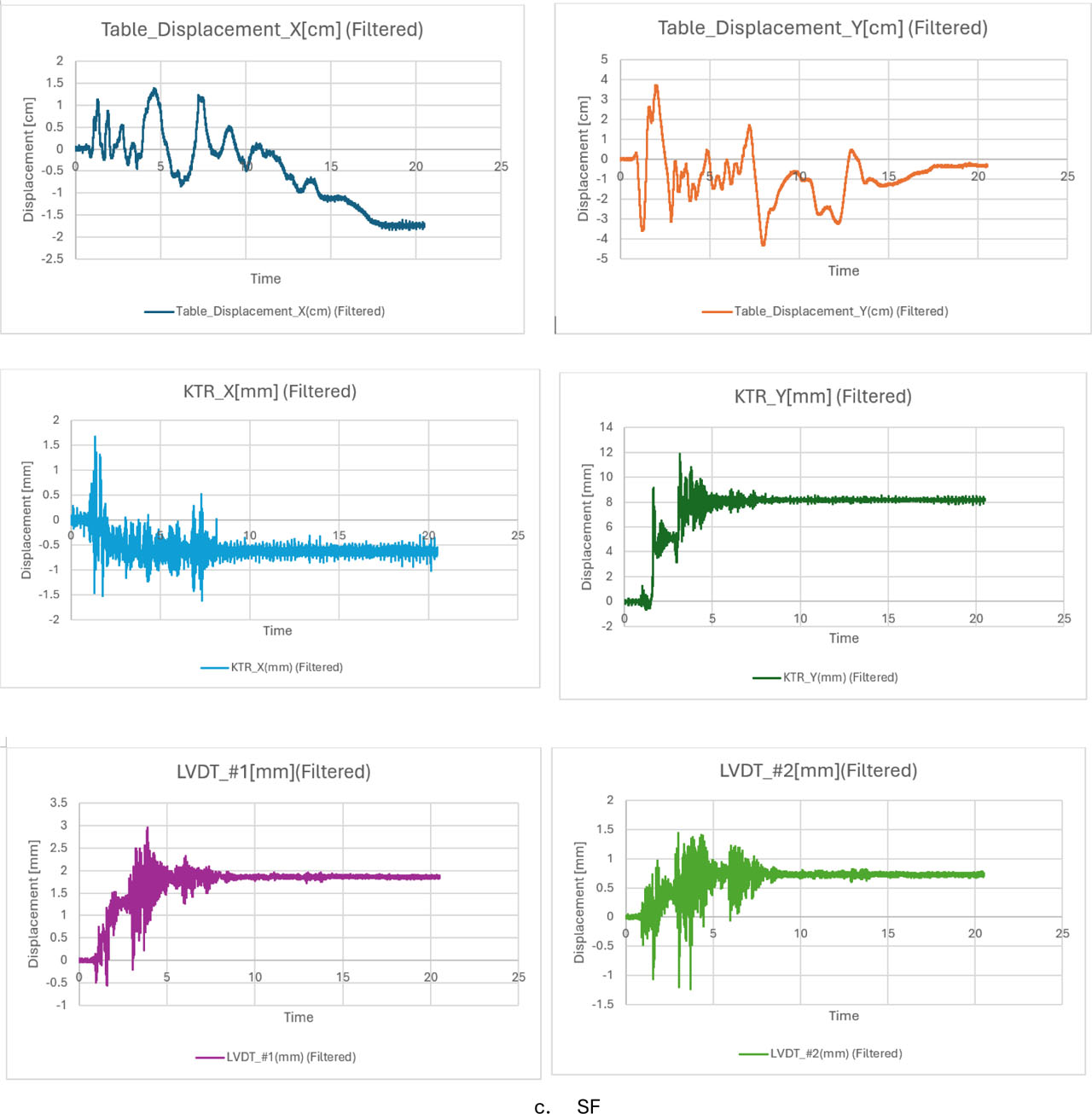
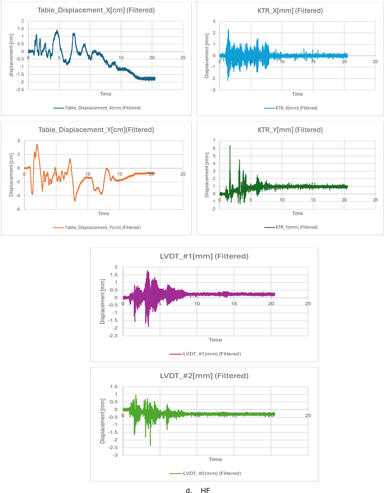
Figure 6:
Displacement tests of shaking table: (a) NC samples; (b) PPF sample; (c) SF Sample; (d) HF sample
A sudden change in stress values was illustrated in the NC strain graph. In contrast to previous mixes, the strains take comparably high levels. The presence of gaps or distribution at the peaks highlights the material's reduced ductility during an earthquake and could indicate early cracking formation that results in a reduction in stiffness. Steel fibers significantly improve the high consistency of the SF strain diagram. The character of stress and strains at certain locations has been reduced by the steel fibers’ cracking bridge. While steel's high stiffness helps reduce long-term seismic deformations, this response seems to be of greater benefit for the strain of the ppf. The image's diagram explains how such fibers are typically highly flexible. They typically have a lower degree than steel. Because these fibers have a significantly smaller modulus of elasticity than steel, they help reduce shrinkage and micro-cracking, but stress/strain values are still high. They are quite acceptable at absorbing this energy, which keeps them from collapsing unexpectedly. The least effective and stable reaction is the HF strain diagram. When steel and polypropylene fibers are combined, synergy is created, as shown in Figure 7.
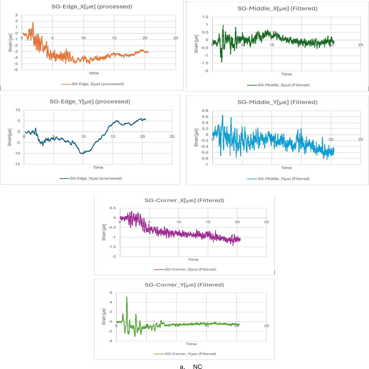
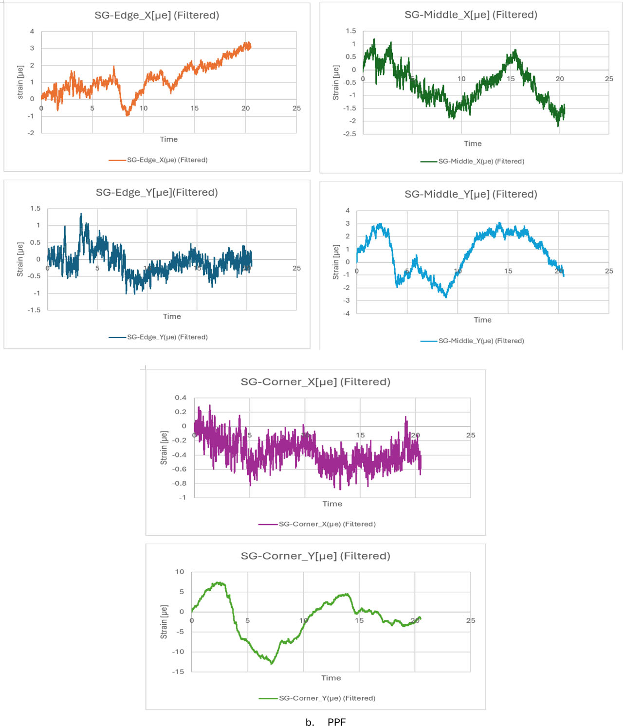
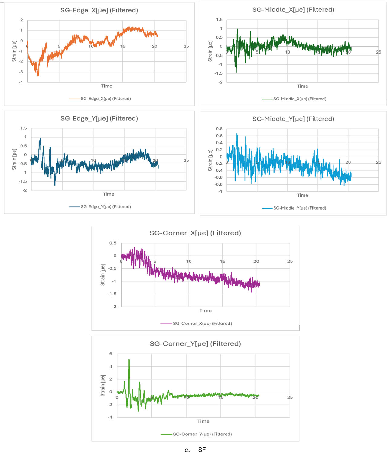
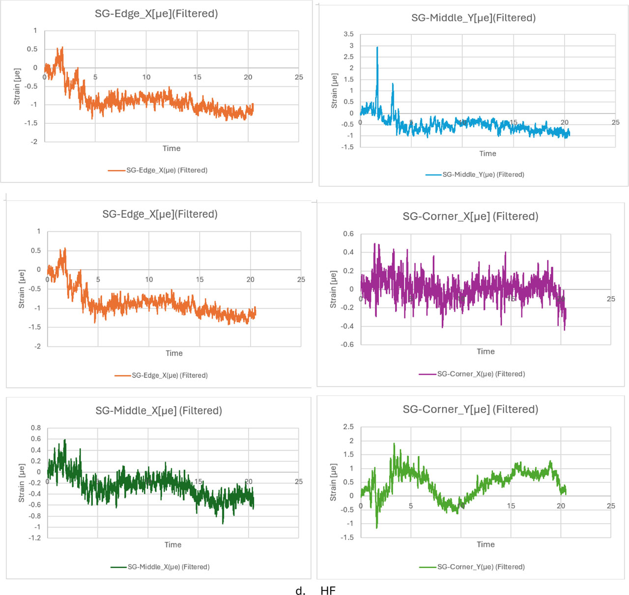
Figure 7:
Strain gauge Relationship between micro strength and time: (a) NC; (b) PPF; (c) SF; (d) HF
Acceleration Amplification in Dynamic Response Analysis. The graphs show that, when compared to the values reported in Table_ Acc, the acceleration values reported in Slab-A are stable, slightly increased at some peaks. It assumes a strong correlation of vibrations between the slab and base. X vs. Y-dots: Y presents greater peaks (up to ~0.6g in filtered graphs) but subsequently faster damping time, although the oscillation into the X direction is continuous and more powerful. High-Performance Concrete vs. Reference Mix: The tendency of this material can be picked up by analyzing the graphs (cured and filtered). High-performance concrete, specifically fiber-reinforced concrete, has more capacity to absorb energy than conventional concrete. After whatever major peak, Slab-A's vibrational amplitude gradually goes away, which is a good indicator of how well it successfully absorbs seismic shocks. Stability and general features: We notice the slab reaction properly and without delay, and track all motions of the table. It illustrates how a high-performance concrete's high stiffness might reduce extremely major elastic deformations when disturbed. When upper harmonics and noise from measuring instruments were removed, the de-noised peaks are much clearer in the filtered diagrams. When the slab's maximal peak ground acceleration (PGA) in the Y-direction reached very high values, it was nevertheless able to move flatly, proving cohesion within the mix and no sign of cracking under high accelerating loads, as shown in Figure 8. for Figure 8 the modulus of elasticity for normal and high-performance concrete (HPC) mixtures with different fiber types The EC (up to 45%) increases significantly from NC to HPC mixtures, which is mainly caused by densification in the microstructure and higher Interfacial Transition Zone (ITZ) density. The relatively high Ec values of the mixtures with metallic fibers (copper fiber-reinforced concrete (HPCCF) and steel fiber-reinforced concrete (HPCSF)) compared to the others in the group can be attributed to the inherent stiffness of the metallic fibers. In contrast, added polypropylene fibers (HPCPPF) were less effective than in the elastic stage based on their low elastic modulus. Moreover, it was found that predictions using the ACI 318 consistently overestimated Ec while an equation from ACI 363R offers a more conservative and properly realistic value suitable for high-strength concrete design.
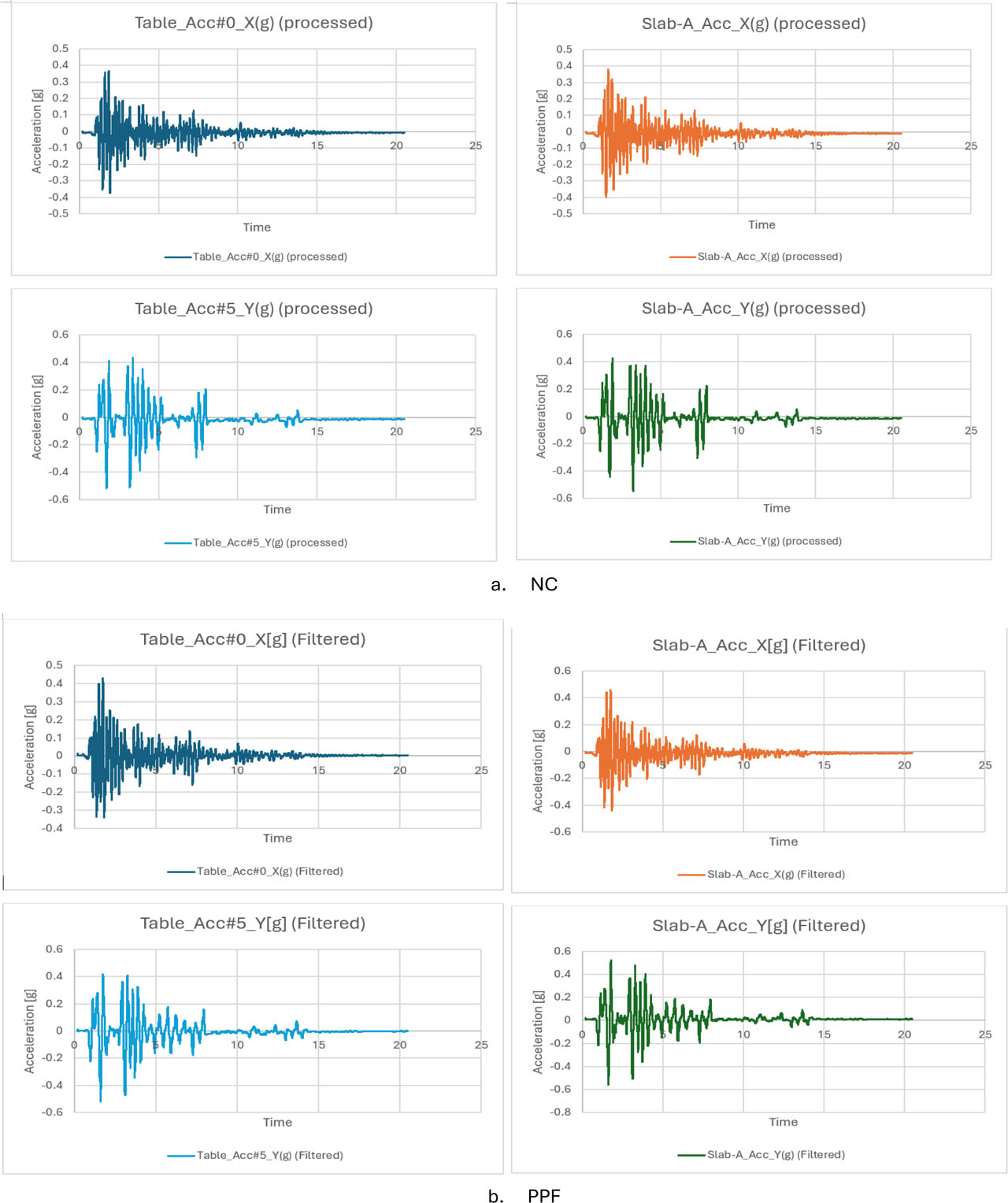
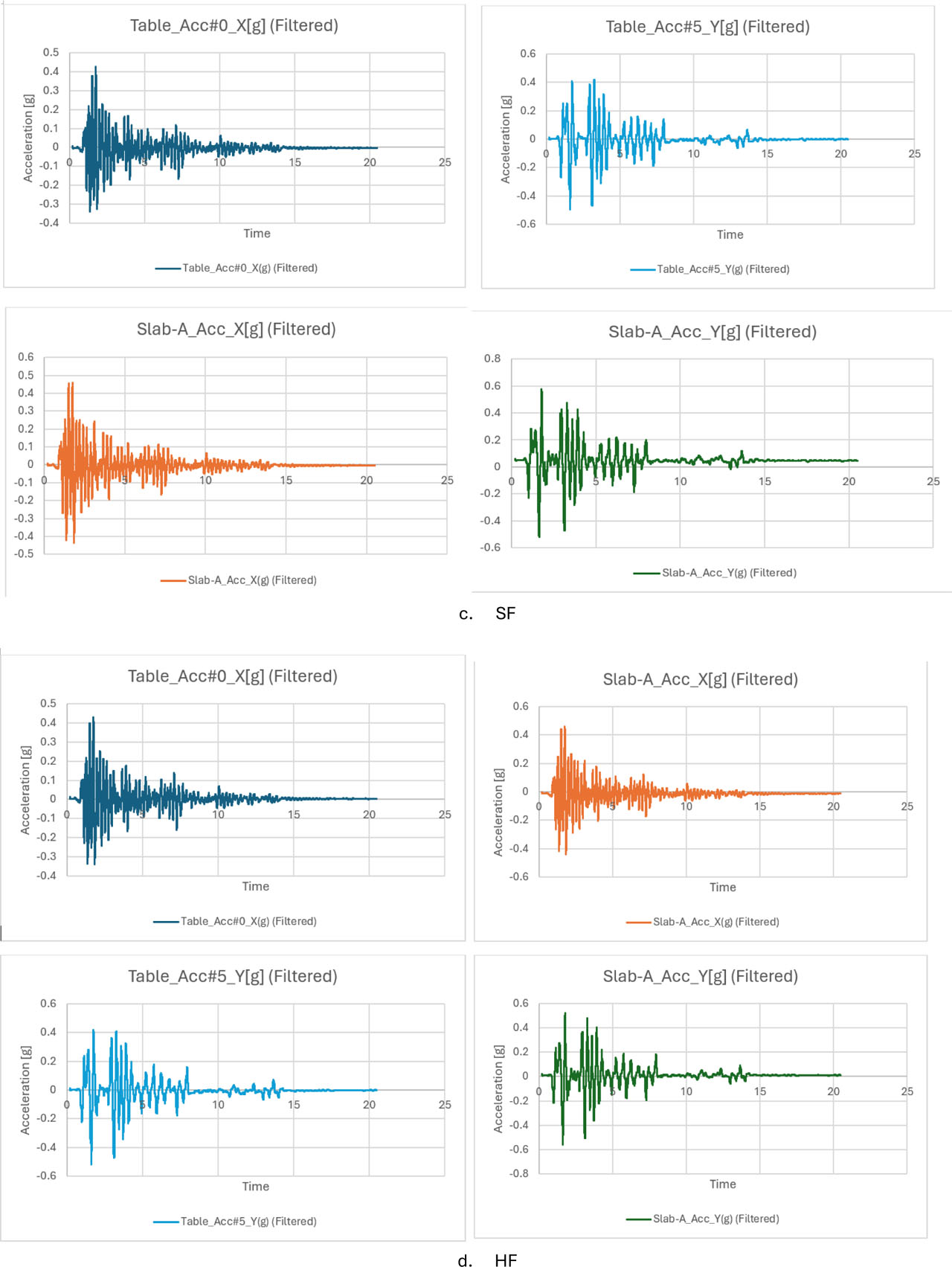
Figure 8:
Acceleration test with time in shaking table: (a) NC; (b) PPF; (c) SF; (d) HF
6. Conclusion
The main conclusions of this study are summarized as follows:
Displacement Analysis
The initial structural response was relatively uniform for all slab specimens. However, the presence of microcracking in the normal concrete (NC) slabs resulted in greater permanent deformation under cyclic loading. In contrast, the hybrid fiber (HF) mixture exhibited minimal relative displacement between the shaking table and the slab surface. This behaviour is attributed to the combined action of fine polypropylene fibers and coarse steel fibers, which created an internal interlocking mechanism that restricted material flow and maintained slab stability even under high vibration amplitudes.
Strain Gauge Response
The strain measurements recorded at different locations indicated that the NC mix experienced rapid failure progression and sharp acceleration peaks. The inclusion of steel fibers (SFs) provided a more uniform strain distribution by resisting the tensile stresses generated during dynamic bending. Furthermore, the HF mixture transformed the brittle behaviour of concrete into a quasi-brittle response, as evidenced by the distributed strain patterns and reduced strain amplitudes. The combined use of steel and polypropylene fibers effectively prevented the propagation of hairline cracks into major structural cracks.
Dynamic and Structural Performance
The hybrid fiber system demonstrated superior vibration filtering capability and significantly reduced acceleration amplification compared with slabs reinforced only with steel fibers. While steel fiber blends improved stiffness, polypropylene fibers enhanced ductility. The combination of both fibers in the HF mixture provided an optimal balance for resisting seismic loads in rigid pavement slabs. In addition, high-performance fiber-reinforced concrete exhibited a higher structural damping ratio than conventional concrete, leading to a substantial reduction in base shear forces transmitted through the pavement–soil system.
Acknowledgements
The authors would like to express their sincere appreciation to Al-Nahrain University for providing the laboratory facilities and technical support that enabled the experimental work of this research.
Notes
[2] Contributed by Author Contributions
N.A.I conducted the experiments, collected and interpreted data, and drafted the manuscript. A.A. conceived and designed the study and supervised the project. Both authors critically reviewed and approved the final version of the manuscript and agreed to be accountable for all aspects of the work.