

1. Introduction
Pile-supported wharves (PSWs) are essential components of port infrastructure because they support berthing operations, cargo handling, and the transfer of heavy operational loads in aggressive coastal environments. In many Asian port facilities, prestressed concrete spun piles are widely used because of their high axial capacity, construction efficiency, and durability advantages in marine applications (Refani & Nagao, 2023b; Zhao et al., 2023). Nevertheless, long-term exposure to chloride-rich seawater, wetting-drying cycles, and tidal action can progressively initiate corrosion in prestressing steel and reinforcement, followed by concrete cracking, section loss, bond deterioration, and stiffness degradation (Mirzaeefard et al., 2021; Yang et al., 2025). Recent durability studies further indicate that chloride ingress in marine-like environments is often coupled with wetting–drying cycles, sulphate–chloride co-exposure, and microcrack development, which can accelerate ionic transport and long-term deterioration of cementitious materials. In prestressed concrete structures, chloride profiles across the concrete cover are also critical for estimating service life and corrosion risk because chloride concentration generally decreases with depth and depends on exposure condition, moisture state, and transport mechanism (Michałek & Gago, 2024; Shaker Amouri & Mahdi Fawzi, 2026). These deterioration mechanisms are particularly critical for aging wharves because they reduce not only member strength but also deformation capacity and material strain tolerance under seismic loading.
Seismic hazards further amplify the vulnerability of PSWs. Past earthquakes have repeatedly shown that port structures can suffer significant foundation damage, permanent deformation, and prolonged service interruption, especially when seismic demand interacts with degraded materials and complex soil-pile response (Chiou et al., 2011; Shafieezadeh et al., 2012; Zhao et al., 2023). Current performance-based seismic guidelines for port structures, such as PIANC (2001), provide strain-based damage classifications for concrete, reinforcing steel, and prestressing steel. However, these strain limits are generally formulated for conventional assessment conditions and do not explicitly incorporate time-dependent corrosion degradation of prestressed spun pile materials. Consequently, applying unmodified strain limits to aged and corroded PSWs may lead to an unconservative interpretation of damage progression and residual seismic capacity.
Recent studies have advanced the seismic performance assessment of pile-supported wharves using refined numerical models, simplified dynamic representations, and performance-based evaluation concepts. Su et al. (2021) developed a three-dimensional finite element framework in OpenSees to evaluate a pile-supported wharf system at different seismic hazard levels and compared computed concrete and prestressing steel fiber strains with design strain limits. Their study confirmed the relevance of strain-level demand parameters in wharf performance assessment, but the analysis was not directed toward corrosion-induced aging of spun pile materials (Petracca et al., 2025). Feng and Gao (2022) proposed an equivalent single-degree-of-freedom (SDOF) model for concrete pile-supported wharves, in which a trilinear backbone curve and Pivot hysteresis model calibrated from pushover analysis were used to reproduce the restoring force characteristics and support seismic fragility analysis with lower computational cost. However, this approach primarily addresses global displacement-based fragility demand and does not explicitly translate local material strain demand into corrosion-adjusted limit states. In a broader fragility context, X. Zhang et al. (2026) showed that performance-based assessment of crane-wharf systems requires appropriate ground motion intensity measures and system-specific damage-state thresholds, because general damage criteria may not fully represent the coupled mechanisms of coastal port systems. These studies indicate that strain-based, displacement-based, and damage-state-based approaches are increasingly important in wharf engineering, yet they remain insufficiently integrated with long-term material deterioration and component-level strain capacity.
A parallel research direction has focused on seismic resilience and life-cycle functionality of port infrastructure. X. Zhang et al. (2026) proposed a seismic resilience framework for pile-supported wharves that integrates structural failure probability with diverse recovery paths, demonstrating that recovery assumptions can strongly affect resilience indices. Such findings highlight the need for more realistic component-level damage indicators that can support post-earthquake decision-making, inspection prioritization, and maintenance planning. For aging marine structures, strain demand in deteriorated pile components is a practical indicator because it directly connects material degradation, local damage, and global serviceability loss. Therefore, corrosion-adjusted strain limits can provide an important bridge between nonlinear structural analysis and life-cycle resilience assessment.
The influence of pile configuration is another key issue in the seismic response of PSWs. Vertical piles tend to be governed primarily by flexural demand, whereas batter piles can attract combined axial-flexural actions and generate different strain distributions under lateral loading. Recent three-dimensional investigations of pile groups with batter piles show that battered configurations can reduce displacement and bending moment demand under some conditions, but their performance remains sensitive to batter angle, soil condition, and ground motion characteristics (Kumar et al., 2026). Similar conclusions have been drawn in soil-pile-structure interaction studies, where pile length, structural height, and soil nonlinearity can significantly alter energy transfer, foundation rotation, and lateral pile demand (Ranjbar et al., 2026). These findings support the need for configuration-sensitive strain evaluation in wharf systems, particularly when vertical and batter piles coexist within the same structural system.
Material-level evidence also supports the need to update strain-based assessment procedures for pile foundations subjected to severe seismic actions. Experimental work on high-strength hollow precast concrete-filled steel tube piles has shown that cyclic flexural demand combined with varying high axial load can strongly affect ductility, local strain distribution, and post-peak response; the same study also reported that several existing design provisions were inadequate for predicting pile behavior under such demanding load conditions (Jasinda et al., 2026). Although these piles differ from prestressed concrete spun piles, the findings reinforce a broader point: pile foundations under earthquake loading must be evaluated not only through global force capacity, but also through local material strain response, axial-flexural interaction, and deterioration-sensitive deformation capacity.
Corrosion research on reinforced and prestressed concrete further demonstrates that material strain capacity is time-dependent. Corrosion reduces the cross-sectional area and mechanical properties of steel, induces cracking and spalling in surrounding concrete, and weakens confinement and bond behavior (Chung et al., 2008; Clark et al., 2005; Shayanfar et al., 2016). Ma et al. (2022) showed that corrosion of transverse reinforcement affects the stress-strain behavior of confined concrete, including peak stress, peak strain, and ultimate strain. For PSWs, Mirzaeefard et al. (2021) emphasized that time-dependent degradation should be reflected in seismic fragility and limit-state updating, while Mirzaeefard and Hariri-Ardebili (2024) further demonstrated that corrosion modeling strategy and climate-change-related parameters can alter corrosion initiation, strength and ductility degradation, limit states, and fragility functions of pile-supported wharves. Their findings highlight that deterioration modeling is not only a durability issue, but also a key variable in seismic performance assessment of aging marine infrastructure. Refani and Nagao (2023a, 2023b) developed corrosion-dependent material models and nonlinear analysis procedures for corroded spun pile-supported wharves. However, existing studies still provide limited direct guidance on how corrosion progression, pile configuration, and material-level strain demand can be integrated into practical performance-based strain limits for aging spun pile-supported wharves.
Based on these gaps, this study develops a performance-based strain limit framework for aging spun pile-supported wharves subjected to long-term corrosion and seismic loading. The analysis considers two representative PSW configurations: a vertical pile system and a combined vertical-batter pile system. A fiber-based finite element approach is used to capture the nonlinear response of corroded prestressed spun piles, including soil-pile interaction, material degradation, and strain demand in concrete and PC bars over a 75-year service period. The novelty of this study is threefold: first, it advances existing displacement- and fragility-based wharf assessments by linking corrosion progression with material-level strain demand to derive corrosion-adjusted strain limits; second, it evaluates how vertical and vertical-batter pile configurations modify strain concentration, ductility degradation, and performance classification; and third, it provides a condition-specific strain-based framework that can complement existing fragility and resilience approaches for seismic performance assessment, inspection prioritization, and life-cycle management of aging marine infrastructure.
2. Methodology
2.1. Geometry of PSW Structure
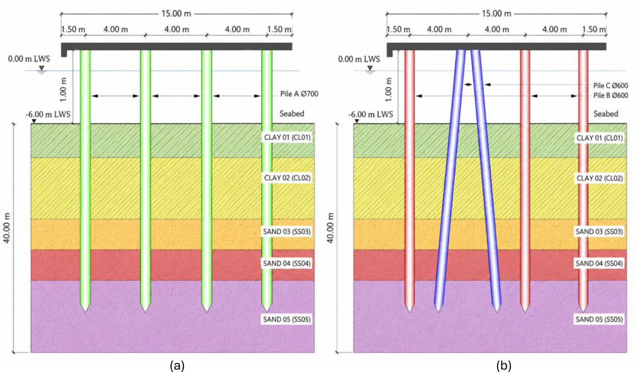
Figure 1:
The Geometry of Structure (a) PSW-A; (b) PSW-B
The analyzed PSW represents a typical small-scale jetty commonly found in Indonesia, comprising a deck structure supported by spun pile foundations. The pile arrangement includes a combination of vertical and batter piles. Figure 1 illustrates the layout of both the PSW and the subsurface profile. The elevation of the wharf's crown is set at +3.00 m relative to the low water spring (LWS). In the configuration with vertical piles, the deck rests on four rows of vertical spun piles (identified as Pile A) with a diameter of 700 mm. Meanwhile, in the configuration featuring batter piles, the deck is supported by three rows of vertical spun piles (Pile B) and two rows of batter piles (Pile C), each having a diameter of 600 mm and inclined at an angle of 5 degrees. The cross-sectional details of Piles A, B, and C are shown in Figure 2, with the top 2 meters of each pile filled with concrete. The structural geometry used in this study refers to the configuration proposed in the research Refani and Nagao (2023b).
2.2. Material Modelling of the PSW
The initial material properties of the spun pile and deck members used in the FB-FEA are summarized in Table 1. The spun pile material properties were selected based on the prestressed hollow circular spun pile specification according to SNI 9156:2023 (Badan Standarisasi Nasional, 2023) and the reference model adopted in this study. The concrete compressive strength for deck and infilled concrete was taken as 30 MPa, which is consistent with the minimum concrete strength requirement for structural concrete exposed to marine environments in SNI 2847:2019 (Badan Standarisasi Nasional, 2019). The yield strength of the reinforcing bars used in the infilled concrete was taken as 420 MPa in accordance with SNI 2052:2024 (Badan Standardisasi Nasional, 2024). These initial properties represent the material condition immediately after completion of the PSW structure before corrosion-induced degradation is applied in the analysis.
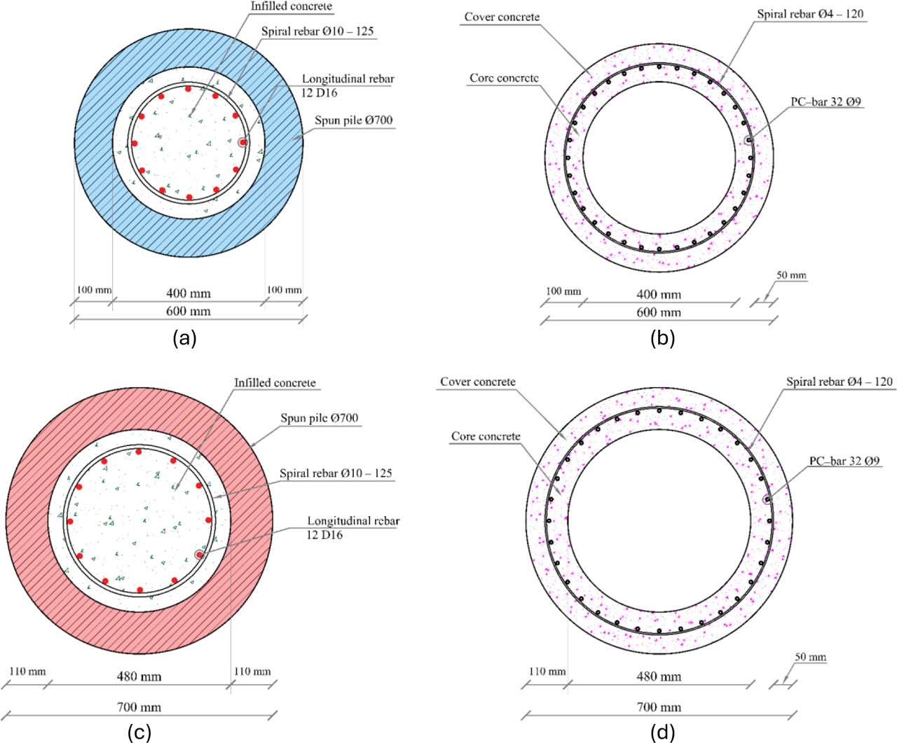
Figure 2:
Spun pile cross-sections (a) Pile A with infilled concrete; (b) Pile A; (c) Piles B and C with infilled concrete; (d) Piles B and C
2.3. Corrosion Effect on the Spun Pile Materials
The degradation of material properties in spun piles begins with the corrosion of PC bars, triggered by chloride penetration from sea salt exposure and cycles of wetting and drying. As rust develops and accumulates, it leads to a reduction in the cross-sectional area of the PC bars, generating internal pressure that causes cracking in the surrounding concrete. This deterioration process weakens the compressive strength of the concrete (Shayanfar et al., 2016), reduces the yield strength of the PC bars (Clark et al., 2005), and diminishes the bond between the steel and the concrete matrix (Chung et al., 2008). In this study, the corrosion effects in marine environments are modeled by modifying the geometry of the PC bars and reducing key material parameters of the spun pile, including the compressive strengths of both the cover and core concrete, as well as the yield strength of the PC bars. Additionally, the analysis accounts for confinement effects by incorporating the reduced compressive capacities of both confined (core) and unconfined (cover) concrete (Refani & Nagao, 2023a) The adopted deterioration mechanism is consistent with previous durability studies showing that chloride transport in concrete is governed by combined mechanisms such as diffusion, capillary absorption, moisture variation, and wetting–drying cycles. Michałek and Gago (2024) showed that chloride concentration profiles in prestressed concrete cover can be used to estimate service life under chloride exposure, while Amouri and Fawzi (2026) demonstrated that combined sulphate–chloride exposure under partial immersion may promote microcracking and ionic connectivity in marine-like conditions.
In this study, the corrosion degree, denoted as ψ, is used as the main deterioration index to represent the progression of PC bar corrosion in the spun pile section. The parameter ψ is expressed as a percentage and reflects the reduction in the effective PC bar area due to corrosion-induced section loss. A value of ψ = 0% represents the initial uncorroded condition, while larger values indicate more severe corrosion damage. The corrosion degree was used to modify the mechanical properties of the spun pile materials, including the compressive strength of the cover and core concrete and the yield strength of the PC bar. The time-dependent values of ψ adopted in this study are summarized in Table 2 for the 0-, 50-, and 75-year exposure conditions.
Table 1:
Material properties of PSW
| Symbol | Description | Value |
|---|---|---|
| fco | Cover concrete compressive strength [MPa] | 52 |
| ɛco | Strain at peak compressive strength of cover concrete [-] | 0.00275 |
| fcc | Core concrete compressive strength [MPa] | 53.95 |
| ɛcc | Strain at peak compressive strength of core concrete [-] | 0.00323 |
| fc | Deck and infilled concrete compressive strength [MPa] | 30 |
| ɛc | Strain at peak compressive strength of deck/infilled concrete [-] | 0.00275 |
| fy−pc | Yield strength of PC bar [MPa] | 1275 |
| fu−pc | Ultimate strength of PC bar [MPa] | 1420 |
| σini | Initial stress in PC bar [MPa] | 781 |
| Es | Elastic modulus of PC bar [MPa] | 190,000 |
| fy−in | Yield strength of infilled concrete rebar [MPa] | 420 |
| fu−in | Ultimate strength of infilled concrete rebar [MPa] | 620 |
| Ein | Elastic modulus of infilled concrete rebar [MPa] | 200,000 |
Equations (1) to (3) quantify how corrosion influences the mechanical characteristics of materials in spun piles. Specifically, these equations are used to calculate the compressive strength of both the corroded cover and core concrete, as well as the yield strength of the corroded PC bar (Refani & Nagao, 2023a).
Where:
fc,corr – definition of the compressive strength of the corroded cover concrete [MPa],
fcc,corr – definition of the compressive strength of the corroded core concrete [MPa],
fc,0 – definition of the initial compressive strengths of the cover [MPa],
fcc,0 – definition of the initial compressive strengths of the core concrete [MPa],
fy,corr – definition of the yield strength of the corroded PC bar [MPa],
fy,0 – definition of the original yield strength of the PC bar [MPa],
ψ – definition of the indicates the degree of corrosion [%]
Table 2:
Time-dependent corrosion degree ψ adopted in the analysis. (Refani & Nagao, 2023b)
| Exposure Time [years] | ψ for Pile A [%] | ψ for Piles B and C [%] | Interpretation |
|---|---|---|---|
| 0 | 0.00 | 0.00 | Initial uncorroded condition |
| 50 | 12.20 | 12.20 | Intermediate corrosion condition |
| 75 | 18.56 | 18.56 | Long-term corrosion condition |
The corrosion mechanism considered in this study is primarily seawater-induced chloride corrosion, which is associated with marine exposure, tidal action, and wetting–drying cycles. Corrosion effects originating from the surrounding soil for the embedded pile portions were not modeled as a separate deterioration mechanism. This assumption was adopted because the available geotechnical data did not include site-specific soil corrosivity parameters, such as chloride and sulfate contents, pH, electrical resistivity, oxygen availability, or redox condition. Therefore, the time-dependent corrosion degree ψ was used as the representative deterioration index for updating the material properties of the spun pile sections, while additional soil-induced corrosion effects were not superimposed in the present analysis.
The corrosion model adopted in this study is deterministic. The corrosion degree ψ was assigned as a predefined deterioration state for each exposure period rather than as a random variable. This approach was selected to provide a controlled assessment of how corrosion-induced material degradation affects the pushover response, ductility reduction, and material strain demand of spun pile-supported wharves. The adopted deterioration parameters follow the corrosion-dependent spun pile material model proposed by Refani and Nagao (2023a), while the analyzed corrosion states represent discrete exposure conditions at 0, 50, and 75 years. Therefore, the present model does not explicitly account for the probabilistic variability of chloride concentration, corrosion initiation time, corrosion rate, temperature, humidity, wetting–drying cycles, or other environmental exposure parameters.
2.4. Fiber-Based Finite Element Analysis
A two-dimensional fiber-based finite element analysis (FB-FEA) model was developed in this study to simulate the impact of corrosion on the cross-sectional area of PC bars and to capture the nonlinear behavior of spun pile materials, including PC bars, cover concrete, and core concrete. The structural geometry and pile-supported wharf (PSW) system modeled in this analysis follow the configuration proposed by Refani and Nagao (2023b), which reflects a typical jetty structure in Indonesia. The deck and pile components were discretized into 1-meter-long elements, with each element featuring a cross-section integrated at five points along its length. Nonlinear fiber displacement-based beam–column (DBC) elements (Mazzoni et al., 2006) were employed using the STKO-OpenSees platform (Petracca et al., 2025). The material nonlinearity of the spun piles was modeled using constitutive models established by Refani and Nagao (2023a), which were applied to each cross-section (as illustrated in Figure 3). Gauss–Lobatto integration was used to compute the combined material response across each section. The initial material properties adopted in the FB-FEA are summarized in Table 1.
Building upon the structural configuration proposed in the previous study by Refani and Nagao (2023b), this research adopts two PSW models for simulation: one utilizing only vertical piles (designated as PSW-A), and the other combining vertical and batter piles (denoted as PSW-B). Both models were developed within a two-dimensional fiber-based finite element analysis (FB-FEA) framework and subjected to long-term corrosion exposure simulations for a period of up to 75 years. The schematic overview of these numerical models is shown in Figure 4, which also includes the fiber discretization scheme used for modeling the spun pile cross-sections within the FB-FEA environment.
The two-dimensional FB-FEA models incorporate p–y curves to simulate the interaction between soil resistance (p) and lateral displacement (y) at varying depths surrounding the spun piles. These curves were developed using the L-PILE software (Isenhower & Wang, 2014), with parameters for clay derived from Matlock’s (1970) model and those for sand adopted from the formulation by Murchison and O’Neill (1984). The resulting p–y relationships for Piles A, B, and C are illustrated in Figure 5.
Subsurface characterization for the PSW site was based on a detailed geotechnical investigation, the results of which are presented in Table 3. The soil profile comprises two clay layers and three sand layers, where the uppermost stratum (CL01) is a very soft clay near the seabed, and the deepest layer (SS05) is a dense sand layer underlying the spun piles. Soil strength parameters, including unit weight, cohesion, friction angle, and consistency indices, were obtained from field and laboratory testing, while N-values were determined through standard penetration tests (SPT), following conventional geotechnical practice in accordance with the Indonesian seismic code (Badan Standarisasi Nasional, 2017).
The N-SPT values in Table 3 are presented as ranges because they represent the minimum and maximum blow counts recorded within each soil layer during the geotechnical investigation. In the numerical model, each layer was idealized as a homogeneous layer with representative soil parameters. Therefore, the N-SPT ranges were not assigned as depth-varying inputs within each layer. Instead, a representative N-SPT value, calculated as the arithmetic mean of the reported range, was used to support soil classification and parameter interpretation. The p–y curves were generated using the adopted unit weight, cohesion for clay layers, and friction angle for sand layers listed in Table 3.
2.5. Pushover Analysis
In this study, a nonlinear static pushover analysis was conducted using a fiber-based finite element approach to evaluate the seismic performance of corroded pile-supported wharf (PSW) structures. The analysis was performed using the STKO interface for OpenSees (Petracca et al., 2025), enabling detailed modeling of material degradation and geometric nonlinearity. Pushover curves were generated by simulating the structural response under increasing lateral displacement (Khazi & Vazeer, 2017). The models incorporate the effects of corrosion over a period of up to 75 years, with each simulation subjected to a constant vertical gravity load of 100 kN. Lateral loading was applied incrementally at the top edge of the wharf deck, with 1 mm displacement steps until the target deformation was reached (Refani & Nagao, 2023b). The designated target displacement corresponded to the lateral movement of the node located at the top of Piles A1 and B1 Figure 6.
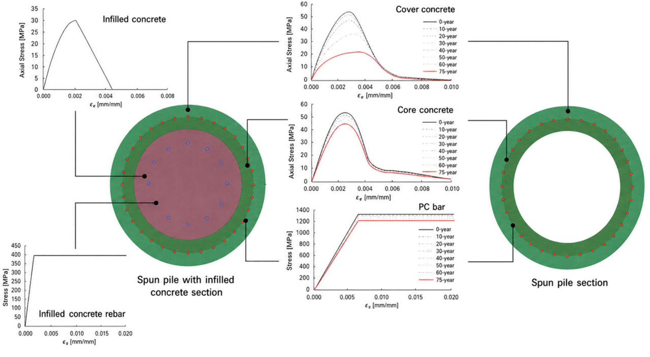
Figure 3:
Fiber discretization of spun pile section in FB-FEA (Refani & Nagao, 2023b)
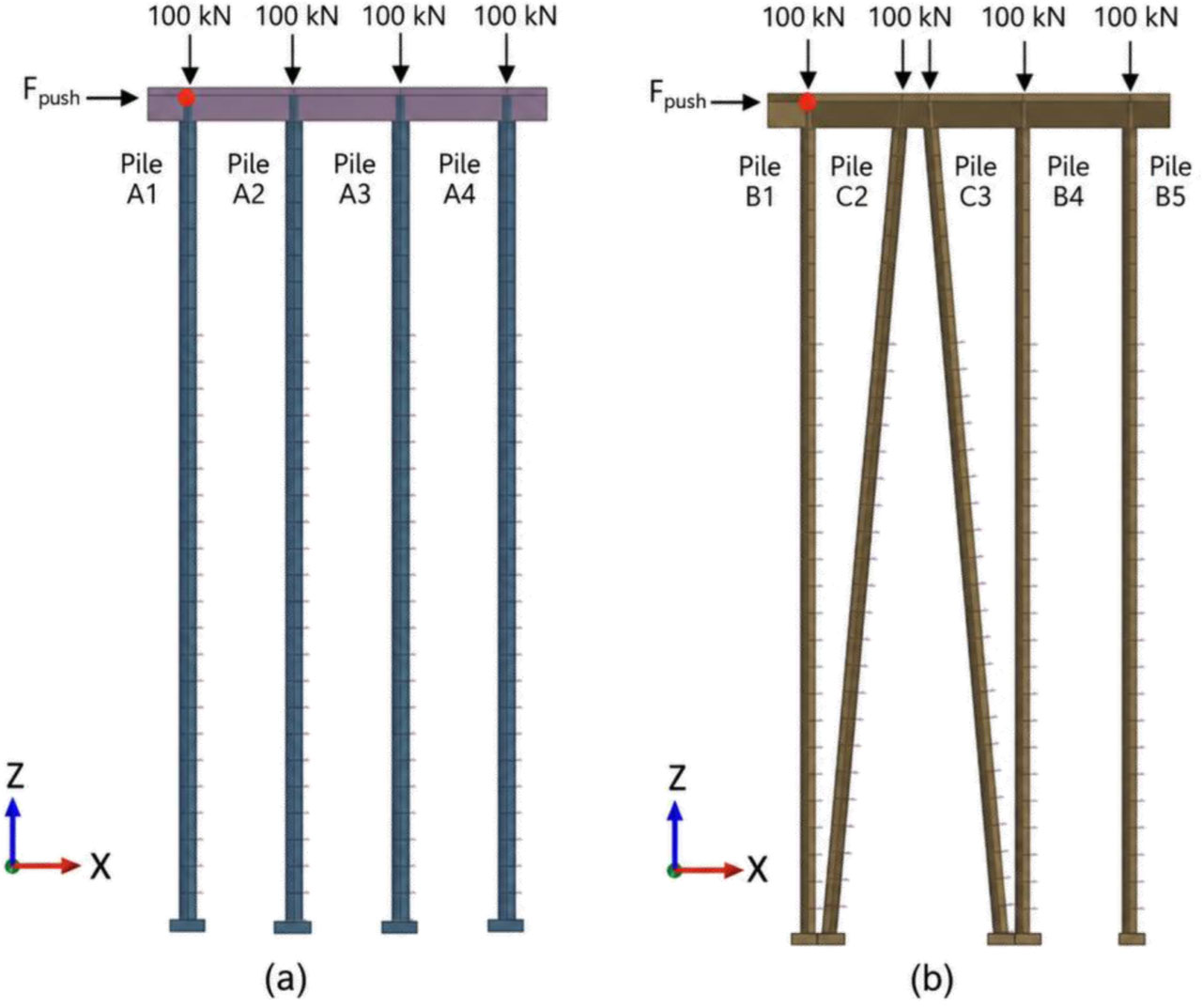
Figure 4:
2D FB-FEA models. (a) PSW-A; (b) PSW-B
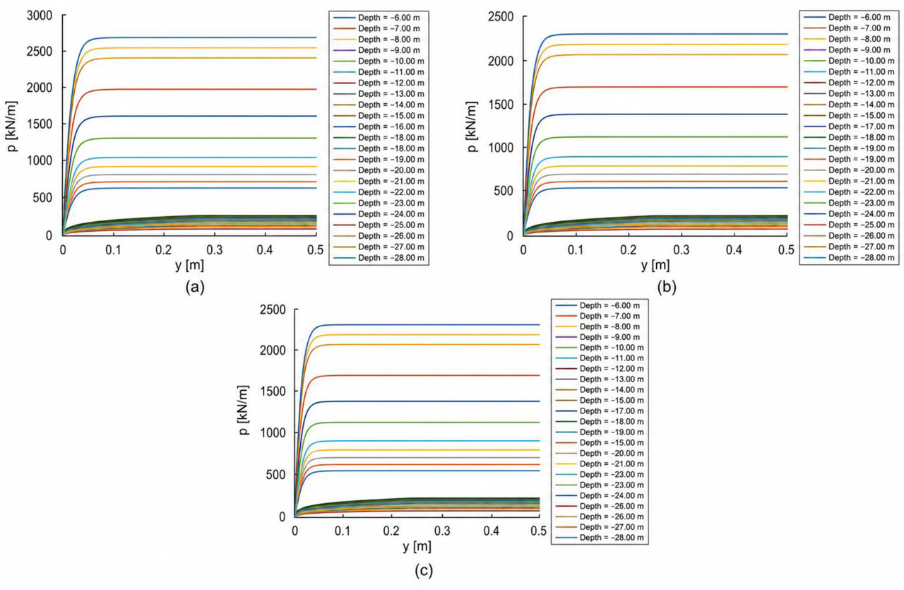
Figure 5:
p–y curve. (a) Pile A (Ø700 mm vertical); (b) Pile B (Ø600 mm vertical); (c) Pile C (Ø600 mm battered). (Refani & Nagao, 2023b)
Table 3:
Representative soil parameters used for p–y curve generation and numerical analysis. (Refani & Nagao, 2023b)
| Layer Code | Soil Type | N-SPT [-] | Layer Thickness [m] | Representative N-SPT | Unit Weight γn [kN/m3] | Friction Angle Φ [°] | Cohesion c [kN/m2] |
|---|---|---|---|---|---|---|---|
| CL01 | Very Soft Clay | 2–4 | 3 | 3 | 10.07 | 6 | 41.19 |
| CL02 | Soft Clay | 5–6 | 9 | 5.5 | 10.33 | 7 | 42.22 |
| SS03 | Silty Sand | 11–19 | 4 | 15 | 10.75 | 22 | - |
| SS04 | Medium Sand | 28–33 | 4 | 30.5 | 11.09 | 30 | - |
| SS05 | Dense Sand | 35–60 | 20 | 47.5 | 11.89 | 34 | - |
To capture the influence of progressive deterioration, the pushover analysis was carried out across various corrosion levels. The nonlinear seismic responses of the corroded PSWs models were observed with FB-FEA approaches. Key response parameters—such as plastic hinge formation, material strain limit and ultimate lateral load capacity—were evaluated to assess the structural degradation. This comparative analysis offers insight into the evolving performance of PSW systems under long-term corrosion exposure and seismic demand.
The nonlinear static pushover analysis was selected to provide a controlled assessment of corrosion-dependent lateral capacity, plastic hinge formation, ductility degradation, and material strain demand. This approach allows the influence of corrosion degree and pile configuration to be compared consistently under incremental lateral displacement. However, the pushover procedure does not explicitly capture cyclic loading effects, ground-motion duration, frequency content, record-to-record variability, or fully dynamic soil–pile–structure interaction. Therefore, the results are interpreted as pushover-based performance indicators and not as a substitute for nonlinear dynamic time-history analysis.
3. Results
The results are presented in terms of corrosion-induced material degradation, global pushover response, ductility degradation, and material strain demand. These response parameters are used to evaluate the influence of corrosion duration and pile configuration on the seismic performance of the analyzed PSW systems.
3.1. Corrosion-Induced Material Degradation
To quantify structural degradation, stiffness reduction factors (η) were adopted based on the methodology proposed by Refani and Nagao (2023b), which integrates corrosion effects into the fiber-based finite element analysis (FB-FEA) of spun pile elements. Table 4 presents the relationship between corrosion degree, rust thickness on PC bars, and the corresponding η values for Piles A, B, and C. For example, in Pile A, a corrosion degree of 18.56% corresponding to a rust thickness of 1.144 mm resulted in a stiffness reduction factor of 0.789, indicating a substantial decrease in effective lateral stiffness. A similar trend is observed in Piles B and C, where η declined from 1.000 (at 0% corrosion) to 0.799 at the highest corrosion level. These reductions reflect the deterioration in structural stiffness due to material degradation and provide a realistic basis for interpreting pushover behavior, plastic hinge formation, and displacement demand. By incorporating these quantified degradation effects into the FB-FEA model, this study enhances the reliability of seismic performance assessments for aging PSW structures.
Table 4:
Stiffness Reduction Factor (η) from FB-FEA at Various Corrosion Levels (Refani & Nagao, 2023b)
| Pile | Years | Corrosion Degree | Rust Thickness of PC Bar [mm] | Stiffness Reduction Factor η |
|---|---|---|---|---|
| Pile A | 0 | 0.00% | 0.000 | 1.000 |
| Pile A | 50 | 12.20% | 0.852 | 0.885 |
| Pile A | 75 | 18.56% | 1.144 | 0.789 |
| Piles B and C | 0 | 0.00% | 0.000 | 1.000 |
| Piles B and C | 50 | 12.20% | 0.669 | 0.950 |
| Piles B and C | 75 | 18.56% | 1.144 | 0.799 |
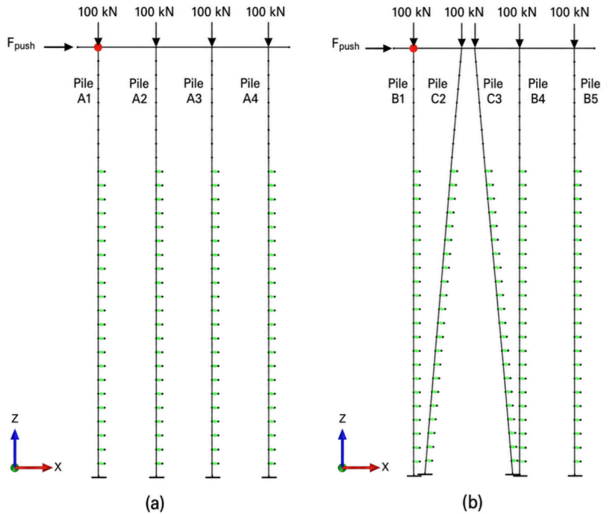
Figure 6:
Loading schematic of non-linear static pushover analysis; (a) PSW-A; (b) PSW-B
3.2. Global Pushover Response of Aging PSWs
The influence of corrosion-induced material degradation on the global structural response of the PSW systems is illustrated in Figure 7. The pushover curves show that both PSW-A, consisting of vertical piles, and PSW-B, consisting of vertical and batter piles, experience a reduction in lateral load capacity as the corrosion degree increases. In the uncorroded condition, both systems develop their highest lateral resistance. When the corrosion degree increases to 18.56%, the peak lateral load decreases by approximately 25% for PSW-A and 28% for PSW-B, reflecting the reduction in material strength and stiffness incorporated in the FB-FEA model.
A distinct reduction in lateral force is observed in the PSW-B curve at a deck displacement of approximately 300 mm. This response should be interpreted as the onset of significant local stiffness degradation in the vertical–batter pile system rather than as a plotting error. In PSW-B, the inclined piles attract combined axial and flexural demands during lateral loading, which promotes earlier strain concentration near the critical pile–deck and in-ground hinge regions. Once the local strain demand approaches the repairable or near-collapse damage range, the model experiences a sudden reduction in lateral resistance followed by post-peak softening.
It should also be emphasized that the deck displacement range of 200–300 mm does not represent a serviceable or allowable deformation level for the PSW system. This displacement is the control displacement used in the displacement-controlled pushover analysis to trace damage progression beyond the elastic range. Therefore, the response in this range should be interpreted as post-yield or severe nonlinear damage-state behavior, not as an acceptable operational condition. The observed response trends support the numerical consistency of the implemented stiffness degradation and strain-based damage interpretation, but they should not be regarded as experimental validation.
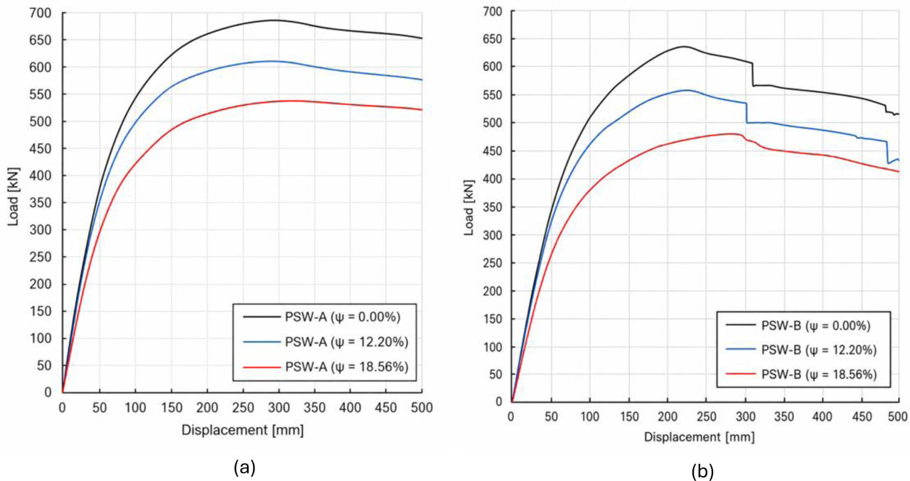
Figure 7:
The result pushover curves of corroded spun pile: (a) PSW-A; (b) PSW-B. The distinct force reduction in PSW-B around 300 mm deck displacement indicates the onset of local stiffness degradation and severe nonlinear damage-state behavior
3.3. Ductility Degradation under Long-Term Corrosion
To further quantify the effects of corrosion-induced material degradation on structural performance, the ductility ratio (μ) was evaluated for both PSW-A and PSW-B models. The ductility ratio is defined as the ratio between the ultimate displacement (Δu) and the yield displacement (Δy), expressed as:
Where:
μ – definition of the ductility ratio [-],
Δu – definition of the ultimate displacement [mm],
Δy – definition of the yield displacement [mm],
As shown in Figure 8, the ductility ratio was calculated using yield displacement assumed at 100 mm, while ultimate displacements were extracted from the pushover curves at various corrosion levels. The results indicate a consistent decline in ductility with increasing corrosion for both structural configurations. For PSW-A, μ decreased from 4.50 at 0% corrosion to 3.00 at 18.56% corrosion. In comparison, PSW-B exhibited slightly higher ductility across all corrosion stages, reducing from 4.70 to 3.10.
3.4. Strain Limit Evaluation and Damage Classification
In the initial condition, the pile-supported wharf (PSW) structure is assumed to be undamaged and operating within the elastic range of its materials. At this stage, the concrete, reinforcing bars, and prestressing strands have not undergone degradation due to environmental exposure or cyclic loading. As such, the PSW should satisfy the criteria defined under Damage Degree I (Serviceable) in the PIANC Seismic Design Guidelines for Port Structures (PIANC, 2001). The corresponding strain limits for this condition are 0.004 for extreme compressive concrete fibers, 0.010 for reinforcing steel, and 0.005 for prestressing strands.
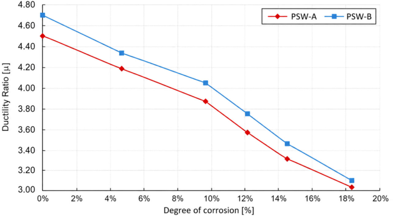
Figure 8:
Comparison of Ductility Ratios between PSW-A and PSW-B
The classification of strain limits for different materials across various damage degrees is summarized in Table 5. This table, adapted from PIANC (2001), presents a comprehensive range of strain thresholds associated with serviceability, repairability, near-collapse, and collapse states. It highlights the increasing deformation capacity required for each level and the role of specific materials—concrete, rebar, and prestressing strands—in defining the structural response under progressive damage. These values serve as a fundamental reference in assessing the condition of PSW systems and are vital for implementing strain-based performance assessment methods.
Table 5:
Summary of Strain Limits per Damage Degree (PIANC, 2001)
| Damage Degree | Material | Strain Limit [-] | Remarks |
|---|---|---|---|
| Degree I – Serviceable | Concrete (extreme fibre compressive) | 0.004 | Minor, no significant damage |
| Degree I – Serviceable | Rebar (reinforcing bar) | 0.010 | Crack control limit |
| Degree I – Serviceable | Prestressing strand (incremental) | 0.005 | Serviceability limit |
| Degree II – Repairable | Concrete (pile-deck hinge) | 0.025 | Typically ∼0.007–0.025 |
| Degree II – Repairable | Concrete (in-ground hinge) | 0.008 | Typically ∼0.005–0.008 |
| Degree II – Repairable | Rebar (pile–deck hinge) | 0.050 | Yield-level ductility |
| Degree II – Repairable | Rebar (in-ground hinge) | 0.010 | Serviceability-level ductility |
| Degree II – Repairable | Prestressing strand (pile-deck hinge) | 0.040 | Post-yield limit |
| Degree II – Repairable | Prestressing strand (in-ground hinge) | 0.015 | Pre-collapse behavior |
| Degree III – Near Collapse | Concrete | Not explicitly specified (≥ ∼0.025) | Double plastic hinges at limited piles |
| Degree III – Near Collapse | Rebar | Not explicitly specified, > 0.05 | Significant post-yield strain |
| Degree III – Near Collapse | Prestressing strand | Not explicitly specified, > 0.04 | Approaching failure |
| Degree IV – Collapse | All materials | Concrete: > ∼0.025; Rebar: > 0.050; Prestressing strand: > 0.040 | Complete structural failure, loss of capacity |
3.5. Strain Demand in Concrete and PC Bars
The strain–displacement relationships for both PC bars and concrete in the deck region of pile-supported wharf structures were analyzed to evaluate the effects of corrosion progression and pile configuration. The data encompass corrosion states at 0, 50, and 75 years, capturing long-term material degradation under seismic displacements.
For the PC bars, the uncorroded PSW-A condition shows a gradual strain increase with displacement, remaining safely below the near-collapse threshold (0.04 mm/mm) up to 600 mm displacement. However, as corrosion advances to 50 and 75 years, the PC bar strains increase more slowly with displacement, indicating reduced stiffness and ductility. Notably, at 75 years, strains approach the repairable limit (0.025 mm/mm) at lower displacements, reflecting diminished load-carrying capacity. PSW-B exhibits a similar trend but with higher strain levels at comparable displacements, suggesting that the presence of batter piles modifies strain distribution and may lead to earlier plastic hinge formation (see Figure 9).
Concrete strain responses display comparable patterns but with higher magnitudes and earlier exceedance of strain limits. In PSW-A, the uncorroded concrete strain remains below the repairable limit until approximately 500 mm displacement, whereas the corroded states reach or exceed this limit at progressively smaller displacements. PSW-B concrete strains are generally higher than PSW-A across all corrosion levels, with the uncorroded state nearing the near-collapse strain limit near maximum displacement. Corrosion further accelerates this trend, reducing the deformation capacity and increasing vulnerability to damage (see Figure 10).
To further support the strain-based observations, the pushover curves presented in Figure 7 demonstrate the structural response of PSW-A and PSW-B across different corrosion durations. For PSW-A, the peak lateral force corresponds to displacements of 413 mm, 385 mm, and 372 mm at corrosion years 0, 50, and 75 respectively, with recorded strains in PC bars of 0.022, 0.020, and 0.018 mm/mm, and concrete strains of 0.023, 0.021, and 0.020 mm/mm at these stages (see Table 6).
In contrast, PSW-B reached its peak force at 336 mm, 329 mm, and 324 mm at corrosion years 0, 50, and 75. Corresponding strains in PC bars were 0.035 mm/mm, 0.032 mm/mm, and 0.030 mm/mm, while concrete strain values were 0.025 mm/mm, 0.023 mm/mm, and 0.022 mm/mm, respectively (see Table 6).
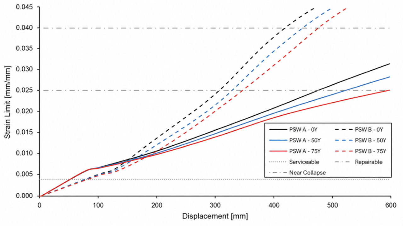
Figure 9:
Strain PC Bar - Deck Displacement Relationship
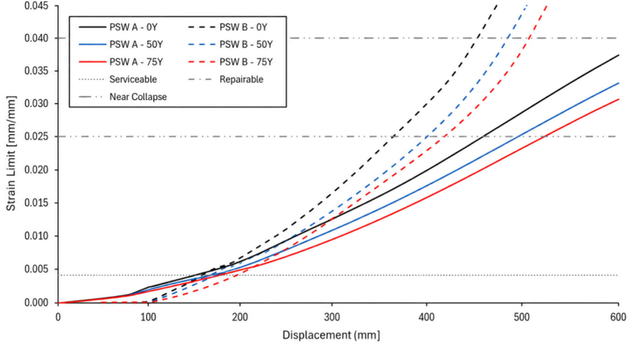
Figure 10:
Strain Concrete - Deck Displacement Relationship
Corrosion reduces the displacement and lateral load capacity at which peak response occurs. Although the strain values recorded at peak response may decrease in some cases due to earlier capacity degradation, the corroded systems reach critical strain thresholds at lower displacement levels, indicating reduced deformation tolerance and earlier damage development.
These strain values indicate that the PSW components transition from repairable damage at early corrosion stages to near-collapse conditions as corrosion progresses. The strain thresholds defined for repairable and near-collapse damage states by PIANC (2001) are met or exceeded near the peak forces, particularly in the corroded PSW-B system.
Table 6:
Deck displacement at peak lateral resistance, Δpeak [mm]
| Configuration | Corrosion Year | Deck displacement at peak lateral resistance, Δpeak [mm] | Strain in PC Bar [mm/mm] | Strain in Concrete [mm/mm] |
|---|---|---|---|---|
| PSW-A | 0 | 413 | 0.022 | 0.023 |
| PSW-A | 50 | 385 | 0.020 | 0.021 |
| PSW-A | 75 | 372 | 0.018 | 0.020 |
| PSW-B | 0 | 336 | 0.035 | 0.025 |
| PSW-B | 50 | 329 | 0.032 | 0.023 |
| PSW-B | 75 | 324 | 0.030 | 0.022 |
3.6. Proposed Corrosion-Adjusted Strain Limits
This study proposes updated strain limits for key components of corroded pile-supported wharf (PSW) structures, incorporating corrosion degree effects and pile configuration variations. Table 6 summarizes the peak displacement values and corresponding strain levels in PC bars and concrete for both PSW-A (vertical piles) and PSW-B (combined vertical and batter piles) at corrosion ages of 0, 50, and 75 years.
Based on these observations, the following empirical correction formulas are recommended to adjust strain limits for corrosion effects, where ψ represents the corrosion degree of the reinforcement bars:
Where:
ψ – the corrosion degree of the reinforcement bars [-],
ɛc – definition of the strain capacity of concrete [mm/mm],
ɛc,corr – definition of the strain capacity of concrete at corrosion condition [mm/mm],
ɛsp – definition of the strain capacity of prestressed bars [mm/mm],
ɛsp,corr – definition of the strain capacity of prestressed bars at corrosion condition [mm/mm],
These relationships highlight the decreasing strain capacity of concrete (ɛc) and prestressed bars (ɛsp) with increasing corrosion severity.
The proposed corrosion-adjusted strain limit equations should be interpreted as linearized correction relationships derived from the deterministic corrosion states considered in this study. These equations are intended to provide a preliminary, model-based adjustment of concrete and PC bar strain limits within the analyzed corrosion range. They should not be interpreted as universal nonlinear corrosion laws or as experimentally validated deformation limits.
4. Discussion
The discussion is organized to interpret how corrosion-induced material degradation and pile configuration affect material-level strain demand, and how these findings support the development of corrosion-adjusted strain limits for performance-based assessment of aging spun pile-supported wharves.
4.1. Effect of Long-Term Corrosion on Seismic Performance
Material degradation due to long-term corrosion is a critical factor influencing the structural performance of pile-supported wharf (PSW) systems, particularly in marine environments. Over time, chloride-induced corrosion leads to a progressive loss of mechanical properties in concrete and prestressing steel, including reductions in compressive strength, yield strength, and bond capacity. In this study, corrosion effects were simulated over a 75-year service period by applying reduction factors to both concrete and prestressing strand materials. These reductions account for rust expansion, cracking, and material section loss, which are commonly observed in coastal environments. As demonstrated by Liu et al. (2025), degradation in reinforced concrete elements significantly impacts strain localization and failure behavior, especially when combined with cyclic loading. Similarly, W. Zhang et al. (2024) emphasized that time-dependent loss of steel area and concrete confinement directly reduces load-bearing capacity and ductility. These insights support the integration of deterioration models into seismic evaluation frameworks, ensuring that nonlinear response and residual strength are properly represented.
The reduction in lateral load capacity and post-peak displacement capacity demonstrates that corrosion affects not only strength but also the deformation capacity and energy dissipation potential of PSW structures. The observed softening of the descending branches suggests earlier plastic hinge formation in the corroded models. These response trends are consistent with the intended implementation of corrosion-dependent stiffness reduction and material strain evaluation in the FB-FEA model. Nevertheless, the results should be interpreted as numerical evidence of response consistency, not as direct validation, because no experimental or field data comparison was conducted in this study.
The recent work of Mirzaeefard and Hariri-Ardebili (2024) reinforces this interpretation by showing that corrosion modeling strategy, exposure conditions, and climate-change-related parameters can substantially modify the corrosion rate, material deterioration, limit states, and fragility response of pile-supported wharves. Their study reported that climate change can increase corrosion rate after 50 years, indicating that deterioration assumptions may strongly influence long-term seismic performance. Although the present study does not explicitly model climate-change scenarios, its corrosion-adjusted strain limit framework is consistent with the broader need for deterioration-sensitive assessment of aging marine infrastructure.
4.2. Role of Pile Configuration in Strain Concentration
Furthermore, the PSW-B structure, which incorporates batter piles, demonstrates more brittle behavior characterized by higher strain levels at maximum displacement compared to the all-vertical pile configuration of PSW-A. This is attributed to the batter piles experiencing a higher combination of axial and bending stresses due to lateral loading, which induces earlier plastic hinge formation and accelerates stiffness degradation. In contrast, PSW-A’s vertical piles primarily undergo flexural stresses with relatively lower strain demands, resulting in a comparatively more ductile seismic response. These findings emphasize the importance of considering pile configuration when assessing strain limits and seismic resilience of corroded PSWs.
The data reveal that PSW-B, characterized by the presence of batter (inclined) piles, consistently exhibits smaller lateral deflections compared to PSW-A yet develops significantly higher strain levels. This behavior can be attributed to the combined axial-flexural demands imposed on the inclined spun piles, which intensify strain accumulation despite limited displacement. In contrast, PSW-A’s vertical piles experience larger lateral deflections but maintain comparatively lower strain magnitudes, indicating a more ductile seismic response.
4.3. Adequacy of Conventional PIANC Strain Limits for Aging PSWs
PIANC (2001) provides a useful reference for classifying material strain limits in performance-based seismic assessment of port structures, particularly for distinguishing serviceable, repairable, near-collapse, and collapse damage states. In the present study, these limits were used as the baseline for interpreting the strain demand obtained from the pushover analysis. However, the results indicate that the interpretation of PIANC-based strain thresholds should consider the degraded material condition of aging spun pile-supported wharves.
The need for deterioration-sensitive strain interpretation is consistent with previous studies. Refani and Nagao (2023b) demonstrated that corrosion-dependent modeling affects plastic hinge formation and seismic response in corroded spun pile-supported wharves, while Refani and Nagao (2023a) showed that chloride-induced degradation reduces the mechanical properties of spun pile materials. Similarly, Mirzaeefard et al. (2021) emphasized that time-dependent degradation should be reflected in seismic fragility and limit-state updating, particularly because corrosion reduces both strength and ductility in marine structures.
In this study, the analyzed PSW systems show that corrosion shifts critical strain demand to lower displacement levels and reduces lateral capacity, especially in the PSW-B configuration where vertical and batter piles interact through combined axial–flexural demand. Therefore, applying the original PIANC strain limits without considering corrosion effects may lead to a less representative interpretation of damage progression in aging PSWs. Equations (5) and (6) are proposed to adjust the concrete and prestressing steel strain limits as a function of corrosion degree, so that the damage classification reflects the actual degraded condition of the spun pile components. These equations should be interpreted as pushover-based, model-dependent recommendations that complement, rather than replace, the conventional PIANC strain limit framework.
4.4. Performance-Based Implications for Seismic Assessment and Life-Cycle Management
The proposed corrosion-adjusted strain limit framework provides a material-level interpretation of seismic damage that can support performance-based assessment of aging spun pile-supported wharves. The results show that global lateral capacity alone is not sufficient to describe the condition of deteriorated PSW systems, because local strain concentration may occur before a complete loss of global resistance is reached. This is particularly important for PSW-B, where the presence of batter piles leads to higher strain demand at smaller deck displacements.
For life-cycle management, the framework can assist engineers and infrastructure owners in identifying critical damage states and prioritizing inspection or maintenance actions. Components with higher concrete strain demand, especially near pile–deck and in-ground hinge regions, should receive greater attention because these locations are more sensitive to stiffness degradation and plastic hinge development. The use of corrosion-adjusted strain thresholds also allows the assessment to be updated as the exposure duration and corrosion degree increase.
The proposed approach can be used alongside displacement-based and fragility-oriented methods. Feng and Gao (2022) demonstrated that an equivalent SDOF model can efficiently estimate global displacement demand and fragility response of concrete pile-supported wharves. However, displacement-based procedures may not fully describe local material damage when corrosion changes the strain capacity of concrete and prestressing steel. Therefore, the strain-based framework proposed in this study complements global response assessment by providing additional information on local damage accumulation, condition-specific strain demand, and maintenance prioritization for aging PSW systems.
4.5. Practical Implications for Inspection, Maintenance, and Retrofitting
Practical Implications for Marine Infrastructure Resilience: Incorporating corrosion-dependent material degradation and pile configuration effects in seismic performance assessments is critical for ensuring safety and durability of PSWs in corrosive marine and seismic environments. The developed modeling framework provides a valuable tool for infrastructure owners and engineers to optimize inspection, repair, and retrofitting strategies.
Inspection programs should therefore prioritize critical hinge regions, particularly in wharf systems with batter piles. Since concrete strain demand reaches serviceability and repairable thresholds earlier than the PC bar ultimate limit in the evaluated cases, monitoring of concrete cracking, spalling, and stiffness degradation should be emphasized during maintenance planning.
In practical asset management, the updated literature suggests that inspection intervals should also consider exposure-zone severity and potential acceleration of chloride-induced deterioration under changing environmental conditions. The proposed strain limits should therefore be interpreted as condition-specific indicators that can be updated when more detailed site-specific corrosion data, climate projections, or probabilistic fragility information become available
4.6. Limitations of the Pushover-Based Assessment
It should be noted that the proposed corrosion-adjusted strain limits are derived from nonlinear static pushover analysis. Although this procedure is useful for identifying lateral capacity degradation, strain concentration, ductility reduction, and plastic hinge development, it does not fully represent dynamic earthquake response. In particular, cyclic degradation, loading reversal, ground-motion duration, frequency content, and record-to-record variability were not explicitly considered. Therefore, the proposed strain limits should be regarded as pushover-based, model-dependent recommendations. Further nonlinear time-history analysis using suites of ground motion records is required to verify and refine the proposed limits for dynamic seismic assessment.
4.7. Limitations of the Deterministic Corrosion Model and Proposed Strain Limits
The corrosion model used in this study is deterministic and therefore does not explicitly represent the randomness of real marine exposure conditions. In actual wharf environments, corrosion progression may be affected by spatial variability in chloride concentration, wetting–drying cycles, temperature, humidity, oxygen availability, concrete cover quality, cracking condition, and maintenance history. Previous chloride-ingress studies also indicate that chloride penetration and service-life estimation are influenced by exposure location, cover depth, diffusion assumptions, and field-measured chloride profiles (Michałek & Gago, 2024). In addition, marine-like deterioration may involve coupled sulphate–chloride exposure, wetting–drying cycles, crystallization-induced microcracking, and changes in ionic connectivity (Shaker Amouri & Mahdi Fawzi, 2026) Therefore, the predefined corrosion degrees adopted in this study should be interpreted as deterministic baseline scenarios rather than probabilistic representations of real exposure conditions.
Climate-change effects were also not explicitly incorporated into the corrosion model. Although previous studies have shown that climate-related parameters may accelerate corrosion after long-term exposure, particularly beyond 50 years, the present study does not simulate climate-dependent corrosion scenarios. Therefore, the proposed strain limits should be interpreted as deterministic baseline estimates rather than climate-adjusted predictions.
In addition, the linear relationship between the proposed strain limit correction factors and corrosion degree is a simplified approximation. This linearized form was adopted to provide a practical first-stage interpretation based on the available deterministic corrosion states. However, the actual relationship between corrosion progression, material degradation, bond deterioration, confinement loss, and strain capacity may be nonlinear.
Finally, the proposed strain limits were derived from numerical pushover analysis and were not directly verified using experimental tests or post-earthquake field observations of damaged wharf structures. Therefore, the proposed limits should be regarded as model-based preliminary recommendations. Future studies should incorporate field-measured chloride profiles, probabilistic exposure parameters, climate-change-adjusted deterioration scenarios, nonlinear corrosion functions, nonlinear time-history analysis, and experimental or field validation to refine the proposed corrosion-adjusted strain limits.
5. Conclusion
This study developed a performance-based strain limit framework for evaluating aging spun pile-supported wharves subjected to long-term corrosion and seismic loading. By integrating corrosion-induced material degradation into a fiber-based finite element analysis, the proposed framework enables the seismic performance of corroded wharf systems to be assessed not only from global capacity parameters, but also from material-level strain demands in concrete and prestressing steel. This approach provides a more condition-specific basis for evaluating aging marine infrastructure than conventional assessments that rely primarily on global displacement or uncorroded strain limits.
The nonlinear pushover analysis showed that long-term corrosion significantly reduced the seismic capacity of the analyzed spun pile-supported wharf systems. At the highest corrosion level, the lateral load capacity decreased by approximately 25% in the vertical pile system and 28% in the combined vertical–batter pile system. The ductility ratio also decreased from 4.50 to 3.00 for PSW-A and from 4.70 to 3.10 for PSW-B, indicating that corrosion progressively reduces deformation capacity and energy dissipation potential.
The strain-based evaluation demonstrated that concrete components are more critical than prestressing steel in the investigated cases. Concrete strains exceeded conventional serviceability thresholds and approached higher damage states in critical hinge regions, whereas the PC bar strains remained below ultimate limits. This finding indicates that concrete strain accumulation should be treated as a key indicator in the performance-based assessment of corroded spun pile-supported wharves.
Pile configuration was found to strongly influence the seismic strain response. The PSW-B system, which incorporates batter piles, exhibited smaller lateral displacement but higher strain concentration due to combined axial–flexural demand. In contrast, the vertical pile configuration showed larger displacement capacity and a relatively more ductile response. These results confirm that strain limits for aging pile-supported wharves should account for pile configuration rather than applying a single generalized threshold.
Based on the observed response, corrosion-adjusted strain limit equations were proposed to support more realistic performance-based seismic assessment. The proposed framework complements recent fragility- and displacement-based approaches by introducing a material-level strain perspective that is sensitive to corrosion degree and pile configuration. Therefore, it can support inspection prioritization, maintenance planning, and life-cycle management of aging marine infrastructure.
It should be noted that the present study focuses on seawater-induced chloride corrosion as the governing deterioration mechanism. Soil-induced corrosion of the embedded pile portions was not explicitly modeled due to the absence of site-specific soil corrosivity data. Future studies should incorporate exposure-zone-dependent corrosion models, including seawater, tidal, splash, and embedded soil zones, to improve the accuracy of long-term seismic assessment of corroded pile-supported wharves.
Future research should extend the proposed framework by incorporating nonlinear time-history analysis, probabilistic fragility assessment, climate-change-influenced corrosion scenarios, and experimental validation of corroded spun pile components. These developments would further improve the reliability of corrosion-adjusted strain limits for practical seismic assessment and retrofit decision-making of aging wharf structures.
Acknowledgements
The authors gratefully acknowledge the financial support provided by PT. Inti Teknik Solusi Cemerlang for this research. The support contributed to the completion of the numerical modeling, data analysis, and manuscript preparation. The views and conclusions expressed in this paper are those of the authors and do not necessarily reflect the official position of the funding institution.
Notes
[1] Contributed by Author Contributions
A.N.R. conceived the research idea, developed the main research framework, supervised the study, and contributed to the interpretation of the results and manuscript revision. K.Y. conducted the numerical modeling, performed the fiber-based finite element analysis, carried out the pushover analysis, processed and analyzed the data, prepared the figures and tables, and contributed to the writing of the original manuscript. M.I.A. contributed to the methodological refinement, validation of the structural interpretation, and critical review of the manuscript. J.V.D. assisted in data preparation, literature review, manuscript formatting, and supporting analysis. All authors critically reviewed and approved the final version of the manuscript and agreed to be accountable for all aspects of the work.