

1. Introduction
In order to minimize brittle failures in more important structural components, dissipative zones—designated locations within structures that absorb and disperse seismic energy are essential to the Capacity Design Philosophy (CDP). During seismic events, these zones which frequently consist of mechanical connectors or particular joint panel zones are intended to experience plastic deformation, enabling the remainder of the structure to remain intact and function elastically (Daniele Casagrande, 2019). This theory underpins steel building seismic safety and reliability. The continual requirement for structural systems with improved ductility and energy dissipation makes this research important. There are many bracing systems, however engineers must balance stiffness and ductility within the capacity design framework. The ability to easily replace damaged pieces following a seismic event reduces repair time and expense (Amiri et al., 2015). The Knee-Braced Frame (KBF) system is important in structural engineering, especially in seismic zones, because it efficiently dissipates energy and mitigates damage. The Knee Member, a structural fuse, is purposely incorporated into the frame. This fuse dissipates and absorbs seismic energy, protecting beams and columns and ensuring framework stability (Naghipour, 2024). KBFs can retrofit existing structures to increase lateral stiffness and strength, offering a variety of seismic performance and resilience options.
Knee-braced frames (KBFs) have garnered significant attention due to their superior seismic energy dissipation and lateral stiffness. Nakahara et al. introduced an innovative retrofit strategy using high-strength vise connections to integrate knee braces into steel frames, allowing effective energy absorption via yielding and buckling, while also simplifying post-earthquake replacement (Banihashem et al., 2023). The H-shaped section member has the best hysteretic performance, followed by the square and C-shaped section members. The slenderness ratio and the component's energy consumption level are inversely associated, and the steel component's single-cycle energy consumption falls as the slenderness ratio rises. (Zhao et al., 2024). The passive energy dissipation systems, and in particular the dampers that can be installed in steel braces to enhance seismic energy absorption and prevent buckling, such as friction (FDs), metallic (MDs), and viscous dampers (VDs), are thoroughly examined in the international literature (Titirla, 2023). The 8.5 m BRB has a higher cumulative plastic deformation and equivalent viscous damping ratio, which results in more effective energy dissipation and damping effects (Wu et al., 2025). Under mild earthquakes, FBRB made up for the standard BRB's insufficient energy dissipation, and under severe ground motions, it was more effective than the conventional BRB at minimizing lateral drifts (Zhou et al., 2022). Chevron-braced frames reduce lateral drifts by 40% to 60%, which greatly enhances seismic performance. Without these supports, structural damage could result from a 300% increase in interstory drifts. Chevron systems improve reliability at all seismic performance levels, according to this study's probabilistic methodology. In the end, they provide an excellent and affordable option for steel buildings that can withstand earthquakes (Alvarado-Valle et al., 2023). In tall buildings, the R-BRACE Frame (RBF) system greatly reduces interstory drift and increases lateral stiffness. It guarantees improved ductility and controlled stiffness decay without changing the vertical load transfer path. These characteristics offer a dependable yielding mechanism at different seismic intensities. As a result, the RBF system is a perfect and effective choice for seismic retrofitting (Ren & Wu, 2023). When compared to uniform damping schemes, multi-level optimization of nonlinear viscous dampers in steel frames lowers maximum inter-story drift and global damage, indirectly reducing demands on NSEs through improved energy distribution and reduced drifts (De Domenico & Hajirasouliha, 2021). In steel ductile braced frames, increasing the damper angle from 30° to 60° greatly increases frame strength and energy dissipation, improving seismic performance (Ghabussi et al., 2021). The high ductility and lateral stiffness required for tall buildings are provided by the dual system of knee bracing and bone connection. These combinations greatly maximize structural response under earthquake loads, as nonlinear analyses show. As a result, they provide a reliable way to guarantee the stability of high-rise frames in cities that are prone to earthquakes (Zahmatkesh et al., 2017). By lowering the steel reinforcing load during seismic shocks, Hybrid Fiber Reinforced Concrete (HyFRC) greatly enhances the structural performance of knee beam-column joints in low to moderate seismic risk areas (Zainal et al., 2021).
The study will be split into three main parts. The first part is a systematic parametric analysis to find out how different knee member lengths (800 mm, 1400 mm, and 1800 mm) affect the ductility, stiffness, and energy dissipation capacity of a standard Knee-Braced Frame (KBF) system. The second part is building and using a validated Finite Element (FE) model in ABAQUS to make a reliable simulation model. This model will be compared against experimental data Zahrai et al. (Zahrai & Jalali, 2014) to see how well it reproduces hysteretic behaviour. The third part is introducing and testing an Enhanced KBF System that adds more supports to show how well it is at controlling excessive lateral displacements.
2. Methodology
2.1. Material Characterization and Constitutive Modelling
The structural response of the proposed bracing system was investigated using a three-dimensional finite element (FE) model developed in ABAQUS/Standard (Abaqus Analysis User’s Guide, 2016). The constitutive behaviour of the steel components was simulated using a nonlinear kinematic hardening model, calibrated against experimental data to accurately represent both the yield and ultimate strength properties Table 1. While a constant elastic modulus of 210 GPa was adopted for all specimens, the ultimate elongation parameters were derived from corresponding experimental measurements. The implemented stress-strain relationships for all material specimens are detailed in Figure. 1.
Table 1:
Section Properties of Validation Model (Zahrai & Jalali, 2014)
| Spec. | Web stiffeners | Knee | Brace | Beam | Column | Steel properties | ||||||
| Distance [mm] | Thickness [mm] | Length [mm] | Section | Length [mm] | Section | Length [mm] | Section | Length [mm] | Section | Fy [N/mm2] | Fu [N/mm2] | |
| KBF 1 | 100 | 10 | 800 | IPE140 | 4300 | 2UNP80 | 3600 | IPE180 | 3500 | 2IPE140 | 333.9 | 482.7 |
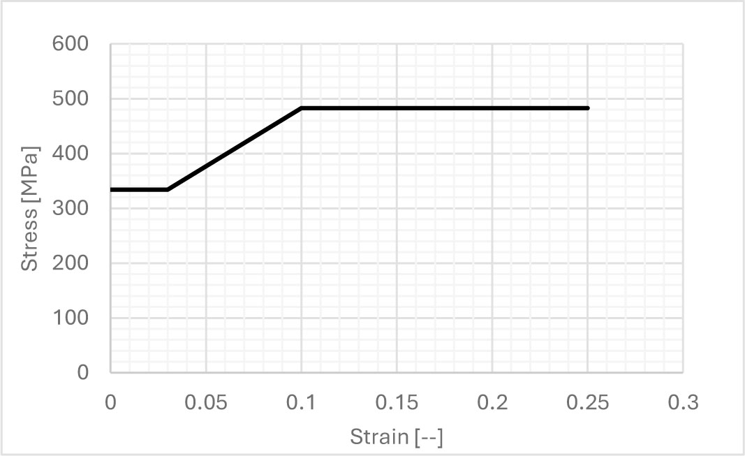
Figure 1:
Uniaxial Stress-Strain Relationship for Steel Material
2.2. Finite Element Model Setup
The experimental setup and corresponding analytical model are presented in Figures 2–3, while Figure 4 illustrates the hysteresis behaviour used for validation.
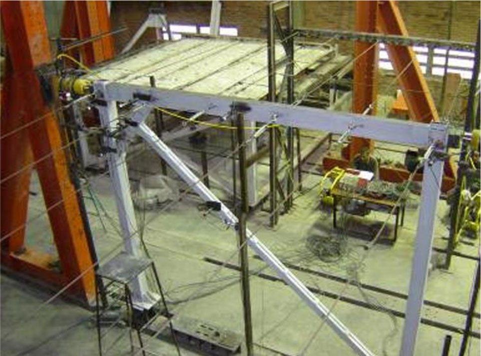
Figure 2:
Experimental Test Setup Configuration (Zahrai & Jalali, 2014)
The numerical simulation utilized three-dimensional solid elements to represent all structural parts, such as columns, beams, knee elements, and diagonal braces. The model consistently used the C3D8R element type, which is an 8-node linear brick with reduced integration. To balance computational efficiency and the capture of localized stress concentrations, a multi-scale meshing approach was applied, featuring element sizes of 50 mm for columns and portal beams, 10 mm for connection plates, and 15 mm for knee members.
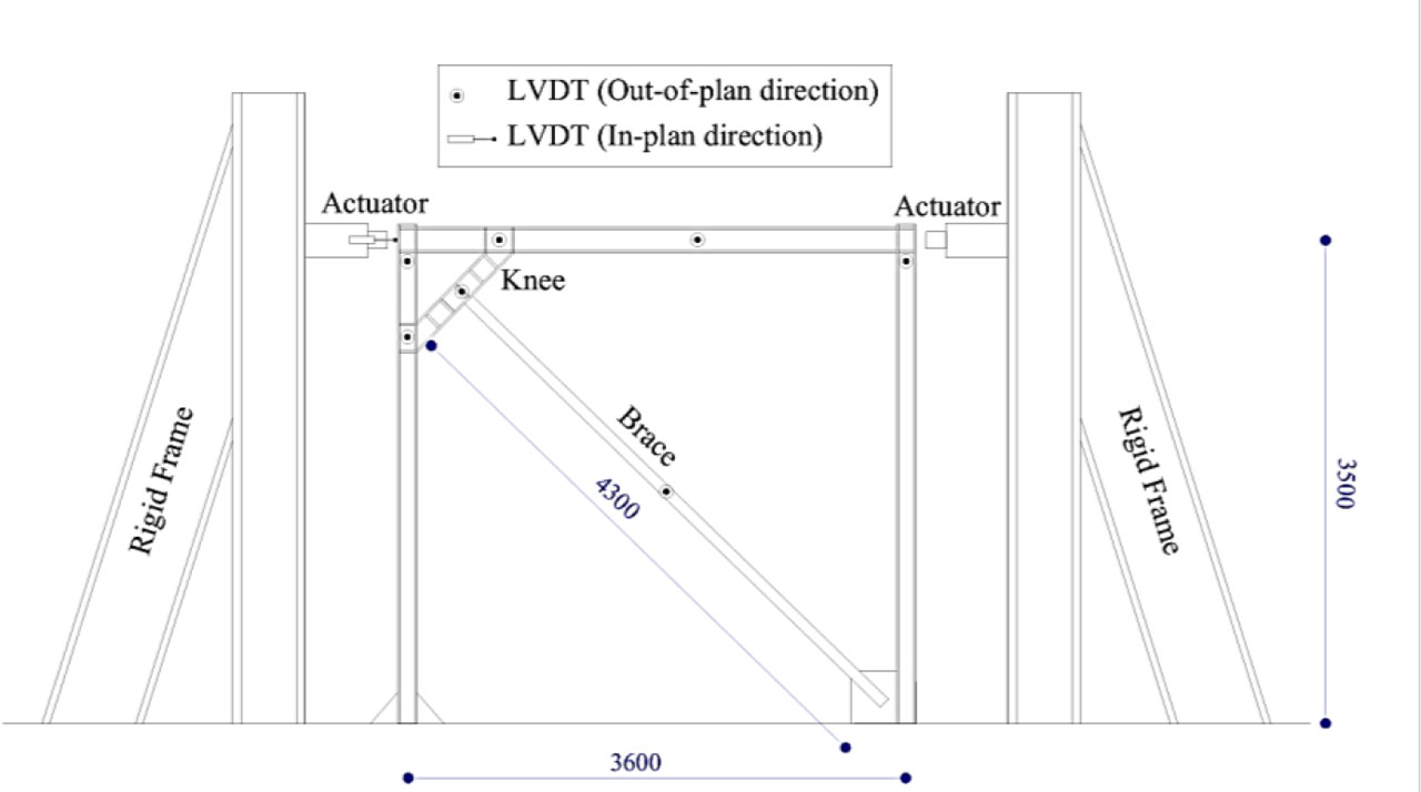
Figure 3:
Analytical Model of Knee-Braced Frame with Component Identification (Zahrai & Jalali, 2014)
Contact interactions between components were modelled using a surface-to-surface discretization scheme. A “hard” contact formulation was defined for normal Behaviour, while tangential interactions were simulated using a penalty friction formulation with a coefficient of 0.2, consistent with established modelling practices. Tie constraints were implemented at all welded connections, as post-test inspections confirmed no weld failure occurred during experimental validation. To accurately replicate the boundary conditions of the laboratory test setup, the base plates were connected to the ground via pinned connections, thereby simulating the confirmed flexibility of the testing apparatus.
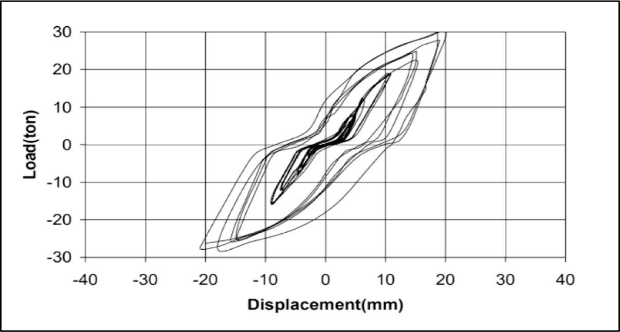
Figure 4:
Experimental Hysteresis Loop Validation (Zahrai & Jalali, 2014)
2.3. Data Collection Loading Protocols and Boundary Conditions
The numerical analysis included both monotonic and cyclic loading protocols, with all experiments continuing until the knee member failed. The cyclic loading adhered to the ATC-24 quasi-static protocol (Vitelmo et al., 1992), utilizing symmetric sets of three cycles with gradually increasing amplitudes. As depicted in Figure 5, the displacement history involved reversed vertical displacements applied in 10 mm increments (10, 20, 30 mm, etc.), with each amplitude level repeated for three complete cycles before moving to the next higher amplitude. The tests concluded when the knee member's failure was observed.
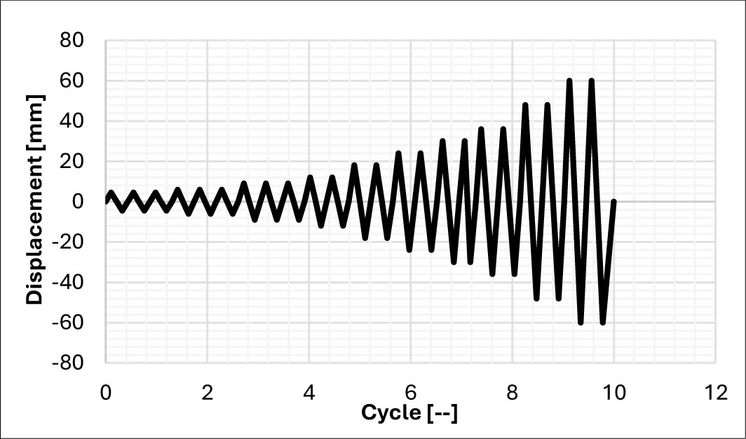
Figure 5:
Quasi-Static Cyclic Loading Protocol Following ATC-24 Guidelines
2.4. Parametric Study Configurations
This study pioneers a systematic quantification of knee member length effects on seismic performance a critical but previously unexamined dimension in Knee-Braced Frame (KBF) optimization. Three strategically varied configurations (Table 2), designated as KBF-T series, maintain identical cross-sections while exploring 800mm, 1400mm, and 1800mm knee lengths to fundamentally characterize this parameter's influence on global structural Behaviour. All specimens incorporate optimized detailing to simultaneously prevent out-of-plane instability and promote controlled plastic hinge formation, ensuring reliable energy dissipation mechanisms. The research employs rigorously validated computational models, benchmarked against experimental data from [27] (Figs. 2–3, Table 1), establishing unprecedented reliability in parametric assessment of KBF systems.
Table 2:
Section Properties and Material Characteristics of Numerical Models
| Sample | Knee Elem./ Length | Brace | Beam | Column | Fy [Mpa] | Fu [Mpa] | E [Mpa] |
|---|---|---|---|---|---|---|---|
| KBF01-T | IPE140 / 800mm | 2UNP80 | IPE180 | 2IPE140 | 333.9 | 482.7 | 210000 |
| KBF02-T | IPE140 / 1400mm | 2UNP80 | IPE180 | 2IPE140 | 333.9 | 482.7 | 210000 |
| KBF03-T | IPE140 / 1800mm | 2UNP80 | IPE180 | 2IPE140 | 333.9 | 482.7 | 210000 |
A parametric study was conducted to evaluate the influence of knee member length on structural performance. Three configurations with varying knee lengths were analyzed (Table 2), designated as KBF01-T, KBF02-T, and KBF03-T, where “T” indicates the traditional configuration prior to enhancement.
2.5. Model Validation
A numerical model, meticulously aligned with the experimental setup described by Zahrai and Jalali (2014), was created using the ABAQUS finite element software. This validation model incorporated the precise geometric and material specifications outlined in Table 1 and strictly followed the physical setup and boundary conditions depicted in Figures 1 and 2. The structural response was simulated by implementing the identical cyclic loading protocol as in the original test, shown in Figure 5. The numerical hysteretic loop obtained was then directly compared with the experimental loop in Figure 4 to verify that the finite element model accurately represented the nonlinear behaviour and energy dissipation capacity characteristic of the Knee-Braced Frame.
3. Results
3.1. Modelling Validation and Hysteretic Response
The load-displacement response Figure 6 characterizes the system Behaviour under cyclic loading, where P represents the applied cyclic load (in tons) at the portal frame's top, and horizontal displacement is measured (in millimeters) at the load application point.
The computational results exhibit a high degree of concordance with the experimental data, thereby affirming the accuracy of the finite element model in representing the structural hysteretic response. As depicted in Figure 6, the numerical simulation effectively replicates the characteristic pinching behavior observed in the experiments, as indicated by the compressed central region and overlapping extremities of the hysteresis loops. This pinching phenomenon can be attributed to minor interfacial slip within the laboratory setup, particularly at the column base connections and beam interfaces, a mechanism analogous to the bond-slip behavior between reinforcement and concrete in composite structural systems.
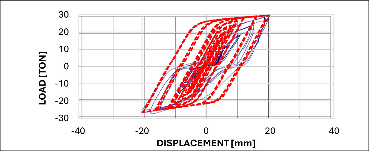
Figure 6:
Validation of Hysteretic Response: Experimental versus Numerical Simulation
3.2. Descriptive Statistics Analysis of Knee Member Length Influence (T-Series)
A parametric study was conducted to evaluate the influence of knee member length on structural performance. Three configurations with varying knee lengths were analyzed Table 2, designated as KBF01-T, KBF02-T, and KBF03-T, where “T” indicates the traditional configuration prior to enhancement. The failure mechanisms and stress distributions were investigated using the finite element model shown in Figure 7.
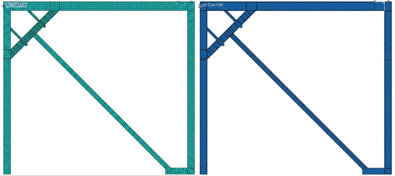
Figure 7:
Finite Element Model of Enhanced KBF System: Mesh (Left); Geometry (Right)
The von Mises stress distributions presented in Figures. 8–10 demonstrate that the maximum stresses in the columns remain below the material yield strength of 482.7 MPa, confirming their elastic Behaviour under design loads. This validates the capacity design approach, ensuring that plastic deformation is concentrated exclusively in the knee member, which functions as a replaceable structural fuse.
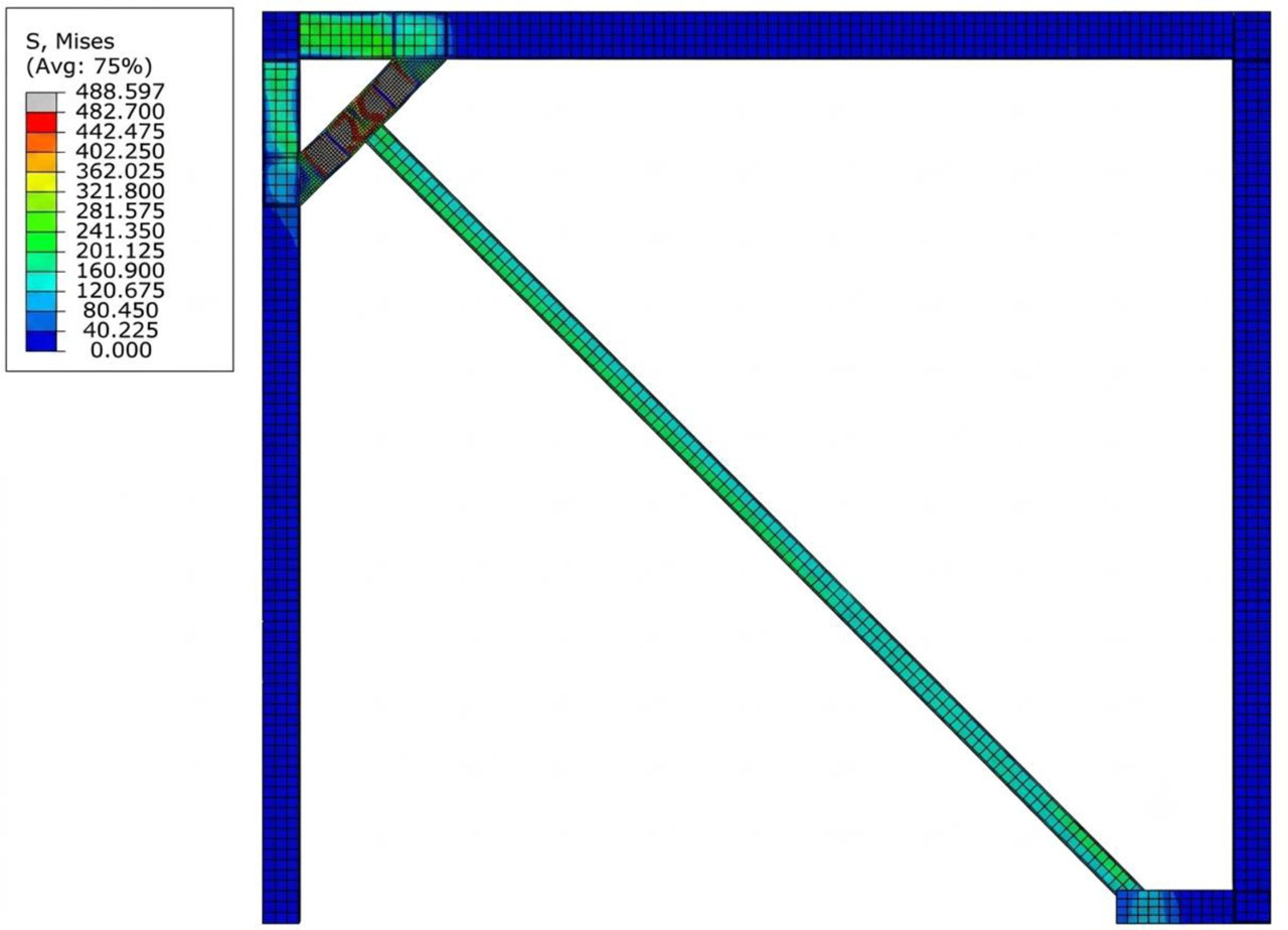
Figure 8:
von Mises Stress Distribution in KBF01-T Model
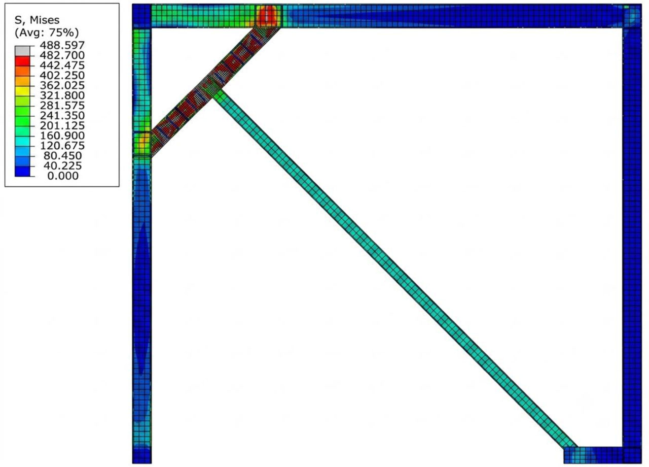
Figure 9:
von Mises Stress Distribution in KBF02-T Model
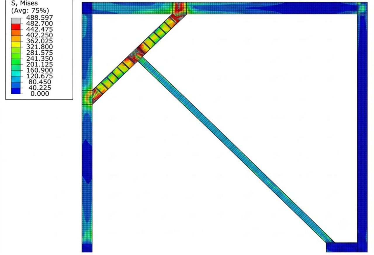
Figure10:
von Mises Stress Distribution in KBF03-T Model
Figures 11–13 present the hysteretic responses, which serve as a metric for evaluating the energy dissipation capabilities of each configuration. The analysis shows that KBF01-T, with its knee element measuring 800 mm, demonstrates the highest energy dissipation. In contrast, the cumulative energy dissipation decreases for KBF02-T (1400 mm) and KBF03-T (1800 mm), indicating an inverse relationship between the knee member's length and its energy absorption capacity. This finding highlights the importance of the knee member's geometry in enhancing seismic performance.
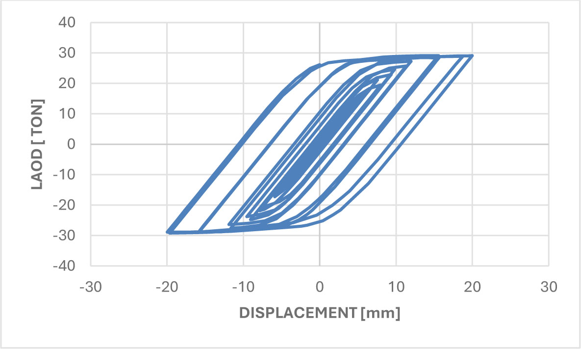
Figure 11:
Hysteretic Response of KBF01-T Under Quasi-Static Cyclic Loading
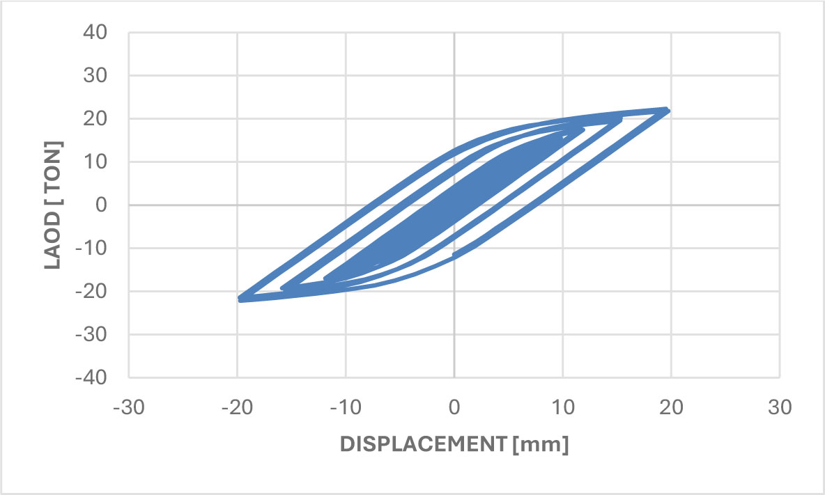
Figure12:
Hysteretic Response of KBF02-T Under Quasi-Static Cyclic Loading
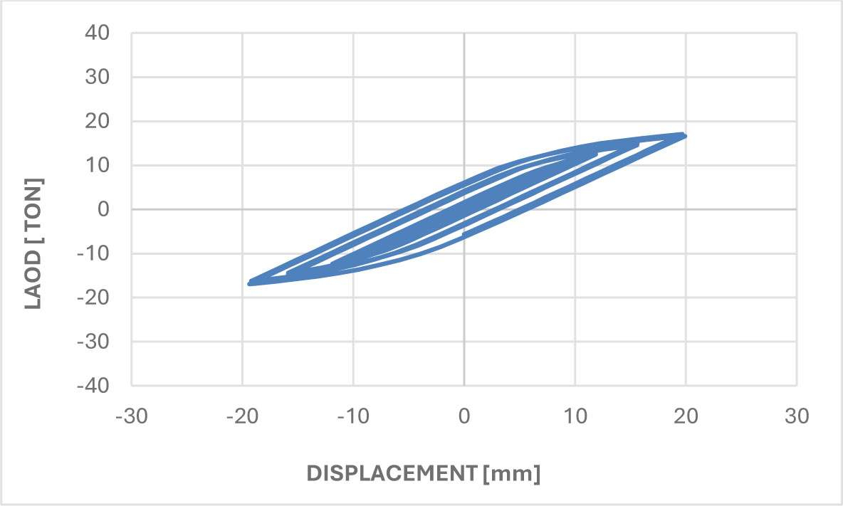
Figure13:
Hysteretic Response of KBF03-T Under Quasi-Static Cyclic Loading
The observed stability and symmetry of the hysteresis loops across all configurations confirm the effectiveness of the capacity design approach
3.3. Quantitative Assessment of Performance Degradation
Table 3 and Figure 14 present a quantitative analysis of structural performance degradation, highlighting a pronounced sensitivity to the length of knee elements. The KBF03-T configuration, characterized by a knee length of 1800 mm, exhibits the most significant reduction in performance, with a 41% decrease in stiffness and a 79% loss in energy dissipation compared to the benchmark KBF01-T model. These results clearly indicate that an increase in knee member length correlates with reduced seismic performance, offering essential design insights for optimizing the energy dissipation capacity in knee-braced frame systems.
Table 3:
Structural Performance Degradation: Stiffness and Energy Dissipation Ratios
| SAMPLE | FORCE [TON] | RATIO [%] | ENERGY [KN.M] | RATIO [%] |
|---|---|---|---|---|
| KBF01-T | 29 | 100 | 46.36 | 100 |
| KBF02-T | 22 | 77 | 20.53 | 44 |
| KBF03-T | 17 | 59 | 9.85 | 21 |
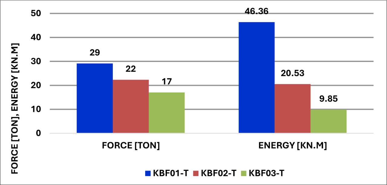
Figure 14:
Performance Degradation: Stiffness and Energy Dissipation Ratios
3.4. Performance of the Enhanced System (N-Series)
Expanding on the known link between longer knee elements and reduced performance, this research presents an improved KBF system that includes carefully crafted additional supports. The new setup, marked with an “N” in the KBFxx-N naming convention and outlined in Table 4, tackles the noted shortcomings with a novel two-stage response approach.
Table 4:
Geometric and Material Properties of Supplemental Supports in Enhanced KBF System
| Sample | H [mm] | B [mm] | W [mm] | F [mm] | D [mm] | S [mm] | Fy [Mpa] | Fu [Mpa] |
|---|---|---|---|---|---|---|---|---|
| KNF01-N | 188 | 92 | 6 | 17 | 7 | 260 | 333.9 | 482.7 |
| KNF02-N | 194 | 92 | 6 | 17 | 10 | 520 | 333.9 | 482.7 |
| KNF03-N | 194 | 92 | 6 | 17 | 10 | 690 | 333.9 | 482.7 |
Figure 15 schematically demonstrates that the system retains typical KBF Behaviour when subjected to moderate seismic forces. However, during intense excitation, it engages controlled support to activate improved energy dissipation and stiffness features.
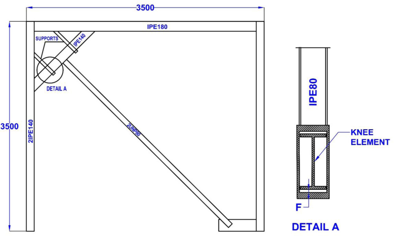
Figure 15:
Proposed dual-phase knee-braced frame (KBF-N) system
Figures 16–18 provide a comparative analysis of hysteretic responses, illustrating the effectiveness of the proposed enhancement. The supplemental supports substantially augment the system's lateral stiffness and energy dissipation capacity, as indicated by the increased area under the load-displacement curves.
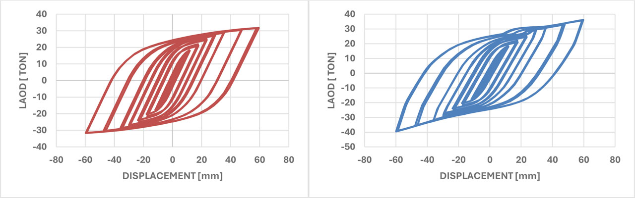
Figure 16:
Comparative Hysteresis Response: (Left) Conventional KBF02-T and (Right) Enhanced KBF02-N
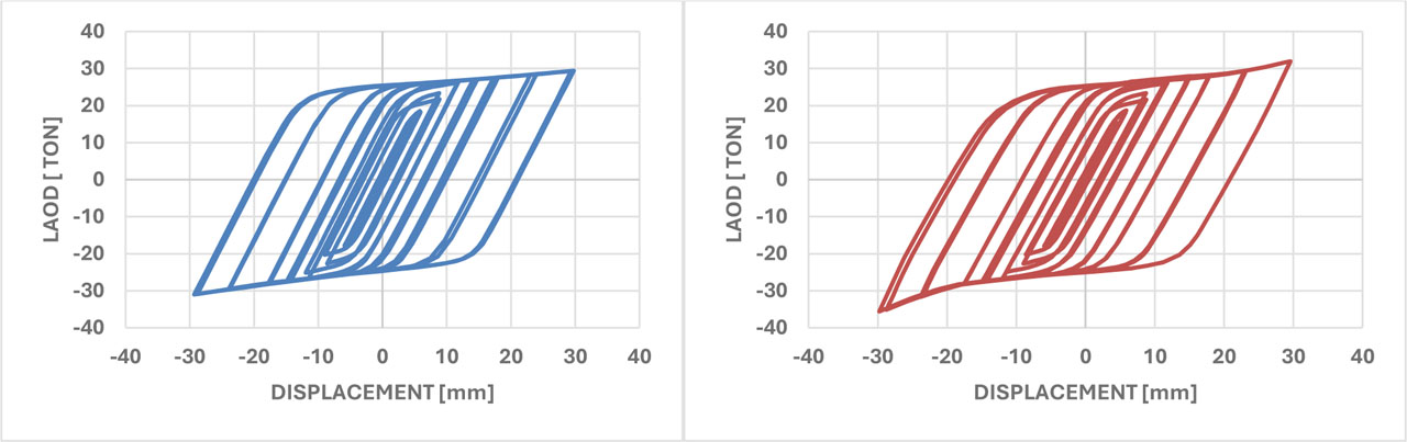
Figure 17:
Comparative Hysteresis Response: (Left) Conventional KBF01-T and (Right) Enhanced KBF01-N
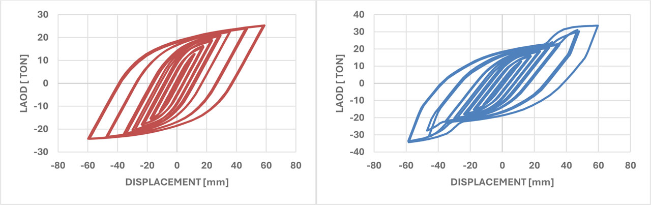
Figure 18:
Comparative Hysteresis Response: (Left) Conventional KBF03-T and (Right) Enhanced KBF03-N
Table 5 presents a quantitative evaluation demonstrating stiffness enhancements ranging from 13% to 26% across various configurations. Notably, the most substantial improvements are observed in longer knee elements, which had previously shown the greatest performance decline in traditional systems.
Table 5:
Stiffness Enhancement in Conventional versus Novel KBF Systems
| SAMPLE | FORCE [TON] | RATIO [%] |
|---|---|---|
| KBF01-T | 31 | 13 |
| KBF01-N | 36 | |
| KBF02-T | 32 | 20 |
| KBF02-N | 40 | |
| KBF03-T | 25 | 26 |
| KBF03-N | 34 |
The adaptive mechanism efficiently limits excessive displacements during severe seismic events while preserving the replaceable fuse function of the knee element. This method enhances structural resilience without compromising reparability. The intervention is especially effective in scenarios that demand improved stiffness characteristics at smaller displacement ranges, offering a practical solution for performance-based seismic design.
3.5. Seismic Performance under Dynamic Loading
The seismic behavior of both traditional and improved KBF systems was assessed through nonlinear dynamic analysis, utilizing the ground motion data from the 1994 Northridge earthquake (Mw 6.7, depth 11.4 km) (Todd et al., 1994). This analysis was performed in ABAQUS/Explicit, where the acceleration record was applied to the bases of the KBF02-T and KBF02-N frames. To ensure an accurate depiction of the structural mass distribution, dead and live loads were transformed into equivalent concentrated masses at the beam levels, based on the composite slab properties outlined in Table 6.
Table 6:
Gravitational Load Calculation
| Materials | Mass per unit volume [Kgf/m3] | Thickness [m] | Unit weight of surface [kgf/m2] |
|---|---|---|---|
| Cement mosaic | 2250 | 0.02 | 45 |
| Sand-cement mortar | 2100 | 0.03 | 63 |
| Concrete slab | 2500 | 0.05 | 125 |
| Concrete beam | 2500 | 2x(0.1x0.25) | 125 |
| Concrete block | - | - | 100 |
| Gypsum and soil | 1600 | 0.02 | 32 |
| White gypsum | 1300 | 0.01 | 13 |
| 503 |
The analytical model depicts a single-story building featuring two main frames, each positioned 5 meters apart and aligned parallel to the KBF direction. The gravitational load was calculated using the formula 1.2D + 1.6L, leading to a distributed load of 923.6 Kgf/m2. This load was then transformed into concentrated forces applied at three reference nodal points (RP, RP-4 and RP-5) along the beam, as shown in Figure 19, to accurately simulate the inertial forces during seismic activity. In order to transfer inertial forces from the reference points to the structural frame without causing artificial localized stiffness or stress concentrations, distributing coupling constraints were employed in ABAQUS. These constraints linked the reference nodes to the top flange of the beam, facilitating a smooth distribution of mass-induced forces while maintaining the natural flexural and warping deformations of the cross-section. Concerning the boundary conditions, the column bases of both frames were modeled as fully fixed. All translational and rotational degrees of freedom at the base nodes were entirely restrained (Ux = Uy = Uz = URx = URy = URz = 0) to simulate a rigid foundation connection. This approach ensured an accurate assessment of the frames' lateral stiffness and energy dissipation capacity under severe seismic loading.
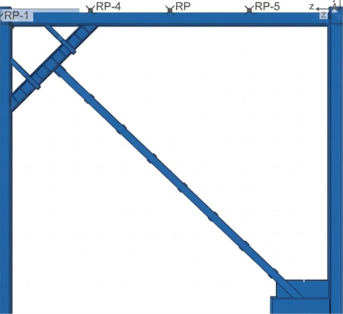
Figure 19:
Loading Configuration: Concentrated Load Application Points on Beam
The dynamic response was evaluated using an implicit direct-integration approach throughout the entire 29-second Northridge earthquake record. A key design parameter in the analysis was a precisely calibrated clearance gap of 7 mm between the knee element and additional supports in the KBF02-N setup. This carefully adjusted gap ensures that supports engage immediately during major seismic events while preventing unintended contact during normal service conditions. Time-history displacement responses were recorded for both structural setups to enable a direct comparison of their seismic performance. As shown in Figure 20, the analysis of these displacement responses highlights the significant advantages of the improved KBF system.
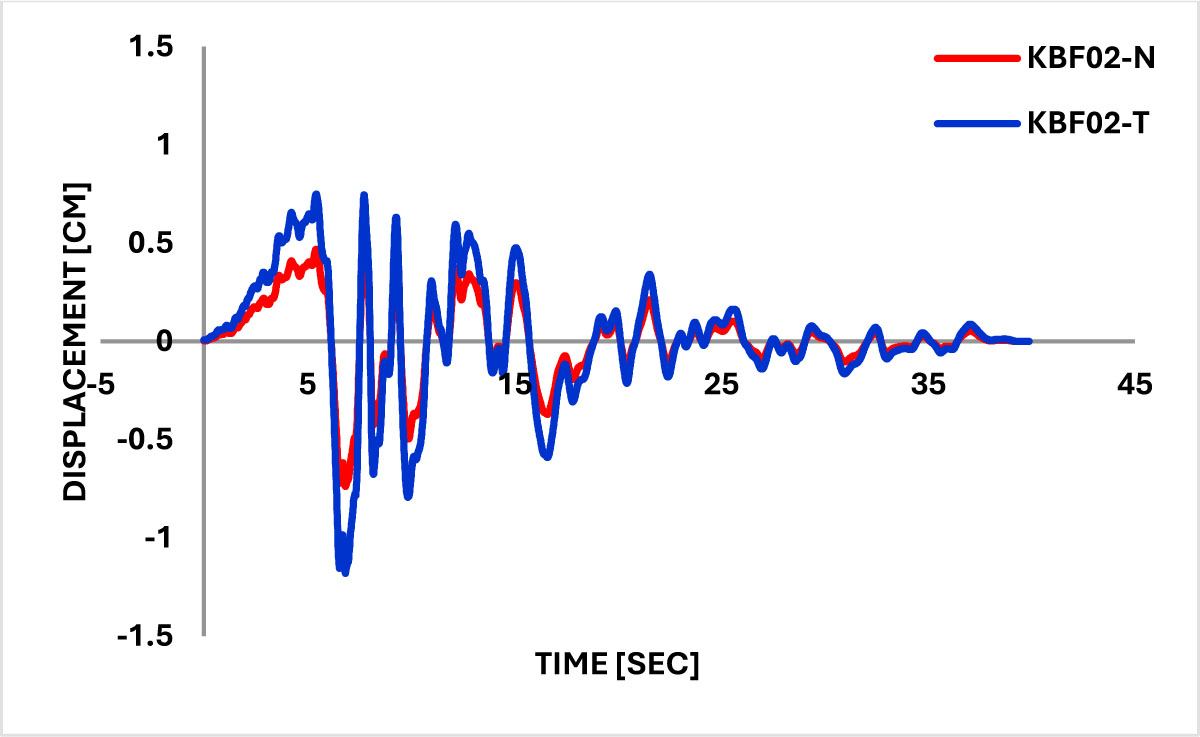
Figure 20:
Time-History Displacement Response: Enhanced vs. Conventional KBF Systems
A comparative examination of the displacement responses reveals a significant improvement in performance. Specifically, the KBF02-T model, indicated by the blue curve, reached a maximum displacement of 1.18 cm, whereas the KBF02-N model, represented by the red curve, exhibited a reduced peak displacement of 0.73 cm. This comparison indicates an overall reduction in peak displacement by approximately 38.14%, thereby affirming the improved efficiency and structural stability of the modified system.
4. Conclusion
4.1. Main Conclusions
The comprehensive numerical analysis yielded three primary quantitative conclusions that address the core objectives of the study:
1. The Relationship Between Knee Length and Performance Degradation
The parametric study (T-Series: KBF01-T, KBF02-T, KBF03-T) demonstrated a distinct inverse correlation between the length of the knee member and the seismic performance characteristics.
Key Finding: An increase in knee length markedly reduces both the stiffness and energy dissipation capacity of the traditional KBF system.
Quantitative Evidence (Table 3): Compared to the benchmark KBF01-T (800 mm knee), the KBF03-T (1800 mm knee) exhibited:
A 41% reduction in stiffness (stiffness ratio decreased from 100% to 59%).
A 79% reduction in energy dissipation capacity (energy ratio decreased from 100% to 21%).
2. Successful Validation of the Capacity Design Approach
The analysis of stress distribution across all traditional configurations quantitatively confirmed that the primary load-bearing members, specifically the columns, remained within their elastic range. This finding validates the core design principle.
A key finding was the successful implementation of the Capacity Design approach, which ensured that plastic deformation was concentrated solely in the replaceable knee member.
Quantitative evidence, as depicted in Figures 8–10, demonstrated that the von Mises stress distributions indicated maximum stresses in the columns remained below the material yield strength of 482.7 MPa, thereby confirming their elastic behaviour under design loads.
3. The Efficacy of Supplemental Supports in Enhancing Stiffness and Displacement Control
The enhanced KBF system (N-Series) effectively addressed the performance deficiencies observed in longer knee configurations, offering superior displacement control under dynamic loading conditions.
Stiffness Enhancement (Quasi-Static - Table 5): The adaptive mechanism significantly increased lateral stiffness, with the most substantial improvement occurring in longer knee elements. Specifically, the KBF03-N model (longest knee) exhibited a 26% enhancement in stiffness compared to its traditional KBF03-T counterpart.
Displacement Control (Dynamic Analysis - Figure 20): During the severe 1994 Northridge earthquake ground motion, the enhanced KBF02-N frame, featuring a calibrated 7 mm clearance gap, demonstrated superior seismic resilience.
Peak lateral displacements were reduced by approximately 38.14% relative to the conventional KBF02-T system.
This confirms the success of the proposed dual-phase mechanism in limiting structural deformations and improving seismic resilience under extreme conditions.
Acknowledgements
I want to sincerely thank the Department of Structural Engineering at Razi University's Faculty of Engineering in Kermanshah for all of their help and advice during the writing of this scientific paper. Their technological know-how and the facilities they provided were crucial to this project's successful conclusion.
Notes
[1] Contributed by Author Contributions
M.A.R. designed the study, supervised the project, and helped with the formal analysis and preparation of the manuscript. A.T.M. carried out the data and FEM analysis. All authors critically reviewed and approved the final version of the manuscript and agreed to be accountable for all aspects of the work.