

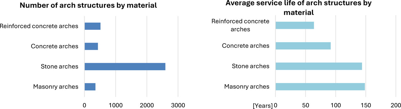
Figure 1:
Overview of arch structures on railway lines in the Czech Republic according to material and their average service life
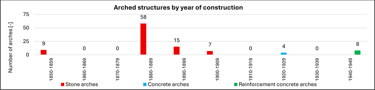
Figure 2:
Number of investigated arch structures by year of construction
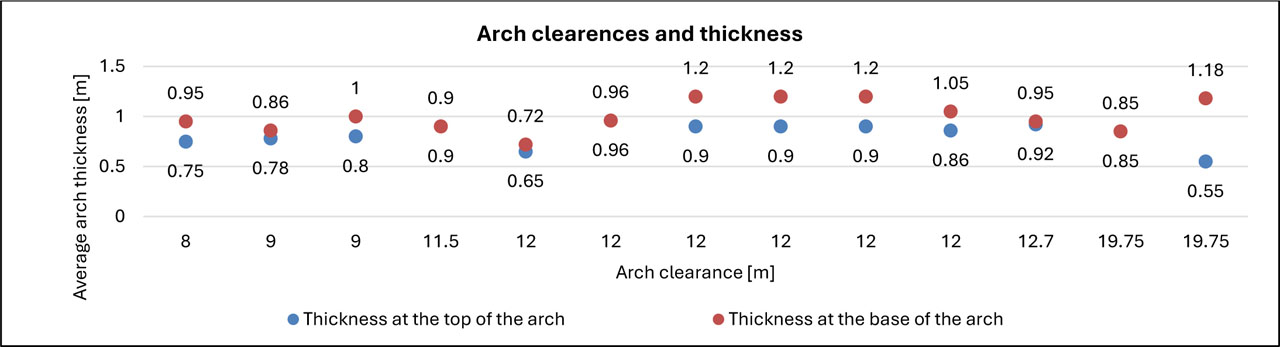
Figure 3:
Thickness of the arch of the main spans at the top and bottom depending on the clearance of the arch at the bottom
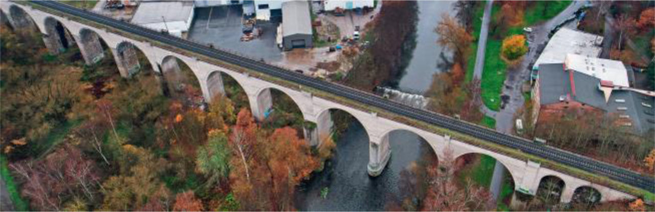
Figure 4:
Cheb Viaduct – view from a drone
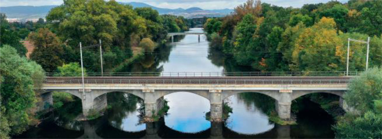
Figure 5:
Bridge over the Ohře River in Bohušovice – view of the bridge
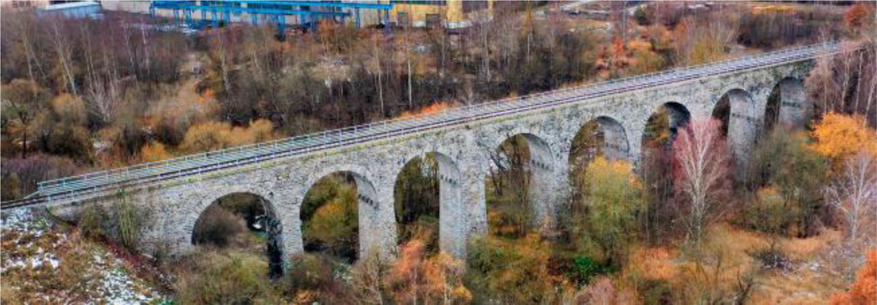
Figure 6:
Viaduct Milevsko – view from a drone
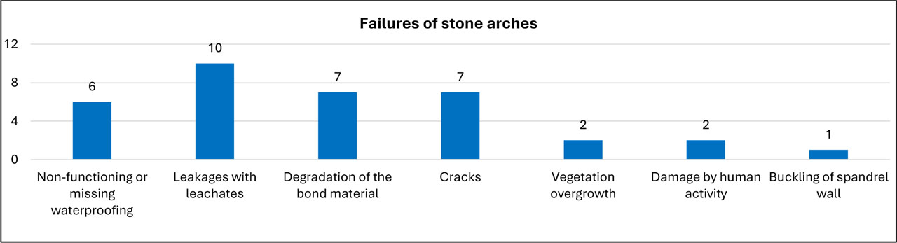
Figure 7:
Types of failures detected on investigated bridges
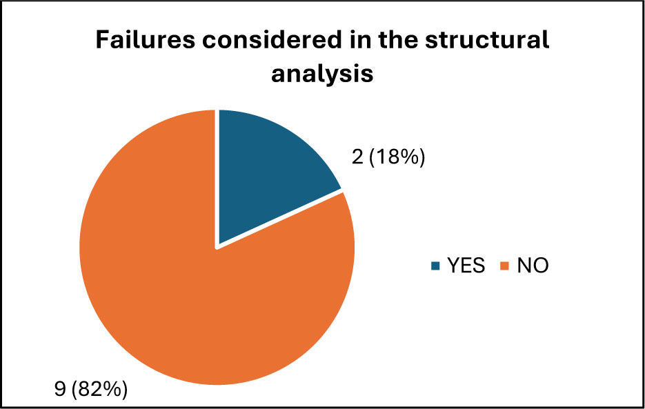
Figure 8:
Considered failures with a direct impact on reliability in the calculation, apart from the actual material parameters, which were always considered
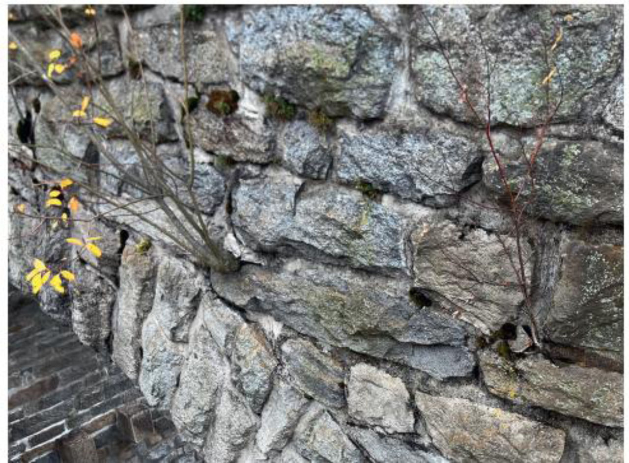
Figure 9:
Milevsko Viaduct - vegetation growing through the structure
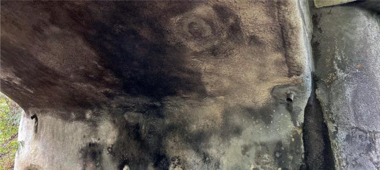
Figure 10:
Bridge over the Ohře River in Bohušovice – moisture retention with shotcrete and leaks through shotcrete
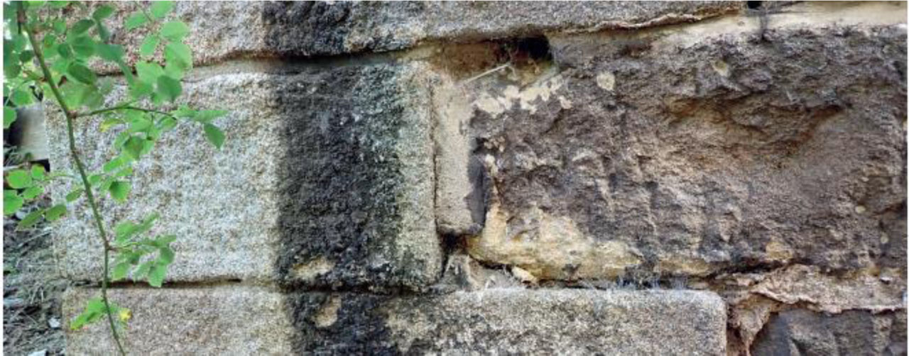
Figure 11:
Viaduct near Ratboř – degradation of sandstone blocks and fallen jointing
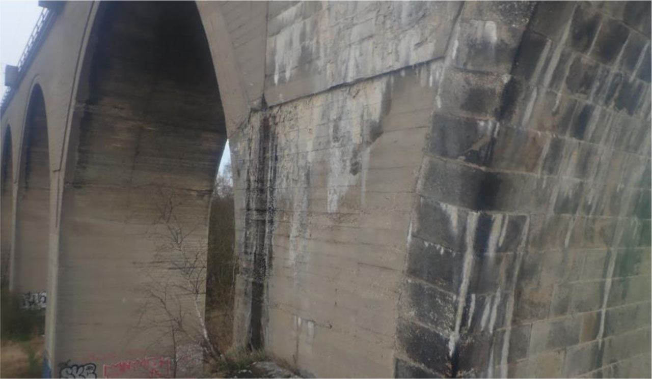
Figure 12:
Cheb Viaduct – Degradation and leaching at the joint between the original stone structure and the newer reinforced concrete structure
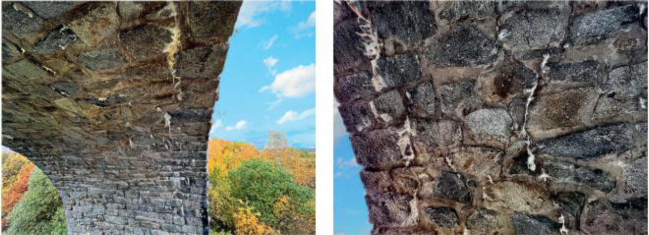
Figure 13:
Milevsko Viaduct – longitudinal cracks with active leakage, joint erosion, and incrustation
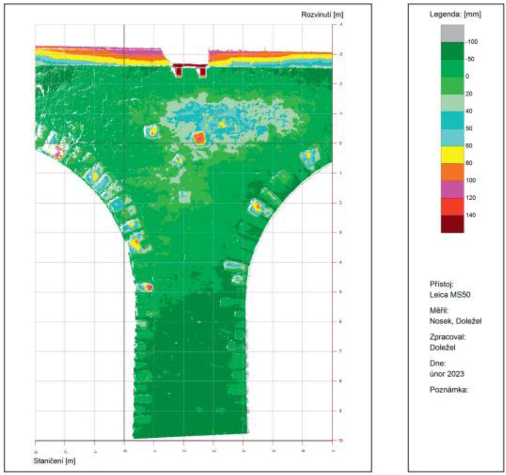
Figure 14:
Results from the method of flat scanning of the buckling of the spandrel wall above pillar P9

Figure 15:
Viaduct Milevsko – Numerical model in LimitState:RING using the limit equity method
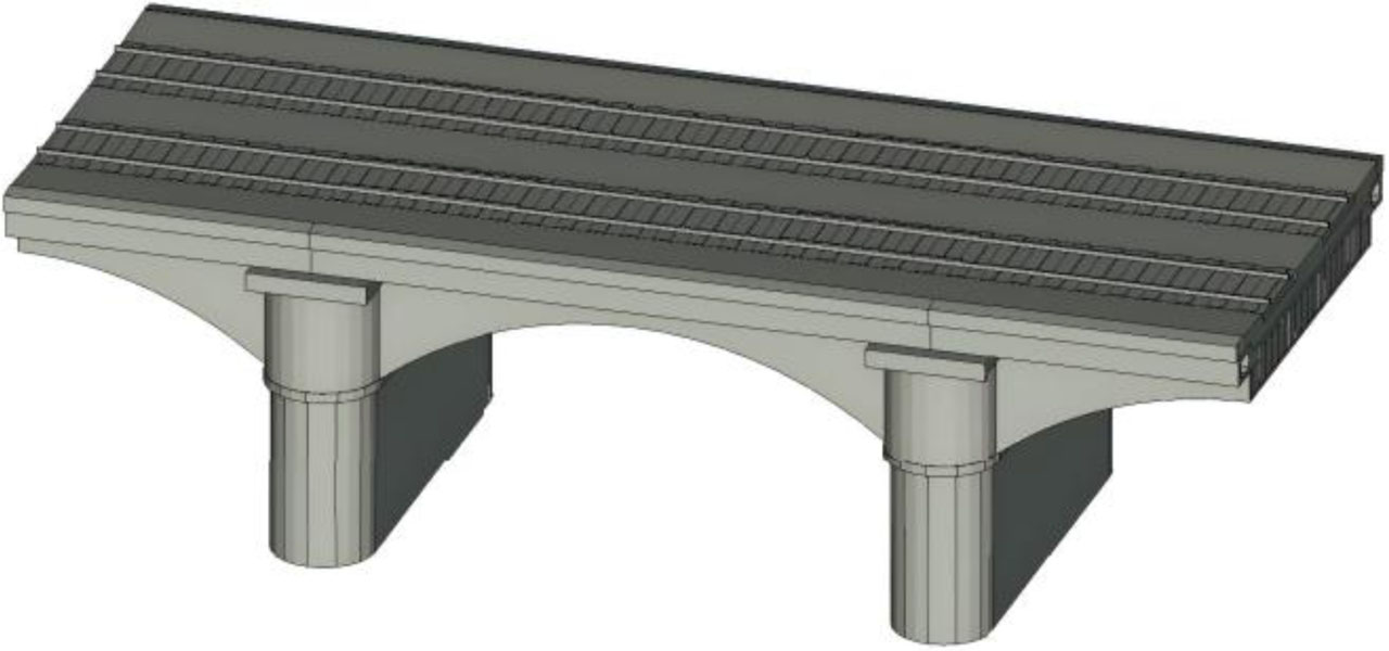
Figure 16:
Bridge over the Ohře River in Bohušovice – Complex model in the ATENA program using volumetric discrete numerical elements
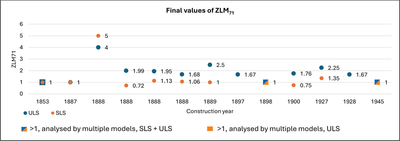
Figure 17:
Load-bearing capacity in ULS and SLS according to the year of construction of the arch structure
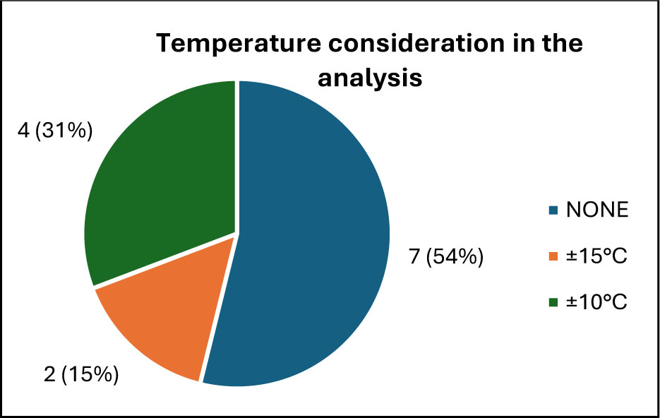
Figure 18:
Consideration of temperature load in analysis