

1. Introduction
Cold-formed steel (CFS) structures have gained significant attention and widespread adoption in low and mid-rise buildings due to their efficient fabrication, short construction time, high strength/weight ratio, and good structural performance. CFS shear wall panels are a practical lateral load-resisting system in these structures. It consists of cold formed steel framing members and sheathing. The framing members include horizontal top and bottom members (tracks) fastened to vertical members (studs) with screws. The shear resistance of CFS shear wall panels primarily comes from the sheathing attached to CFS framing members using fasteners, usually self-drilling screws. A variety of sheathing materials such as oriented strand board, gypsum wall board, and steel sheathing board are commonly used in these wall panels. In recent years, CFS shear walls with steel sheathing boards have become widely used to resist lateral loads, such as wind and earthquakes, in highly seismic regions.
Several experimental studies such as Yu and Chen (2011), Javaheri-Tafti et al. (2014), Mohebbi et al. (2015), Attari et al. (2016), Al-Kharat and Rogers (2019), Pehlivan (2023), and Zhang et al. (2024) investigated the behaviour of CFS shear wall panels with steel sheathing under lateral loads, aiming to evaluate their shear strength for practicing engineers and designers. A key conclusion from these studies is that the shear strength and overall performance of CFS shear walls were primarily influenced by the failure modes of the fastener connections between CFS members and the steel sheathing. Similar conclusions have been drawn in other experimental studies such as those by Zeynalian et al. (2012), Esmaeili et al. (2015), Rizk et al. (2018), Martínez and Xu (2021), Alshamsi (2022), and Ahmed et al. (2024).
Based on these observations, some researchers have focused on optimizing the connection details between cold formed steel members and steel sheathing to enhance the overall performance of CFS shear walls. For instance, Martinez (2023) found that the use of self-drilling screws with smaller threaded diameters and closer spacing (less than 150mm) can significantly enhance the lateral load capacity of CFS shear walls. Nguyen and Tran (2023) highlighted the importance of connection geometry in the lateral performance of CFS shear walls, providing recommendations for fastener spacing and arrangements to enhance the performance under lateral loads. Xie et al. (2018) experimentally investigated the performance of CFS shear walls using self-piercing rivets (SPR) as a viable alternative to traditional screw connections, demonstrating that SPRs significantly enhanced the shear strength of CFS shear walls.
Additionally, several finite element modelling techniques have been developed to simulate the behaviour of CFS shear walls and their connections under monotonic loading (Xie et al., 2024; Medriosa et al., 2024; Kechidi & Iuorio, 2023; Koutilya & Narayan, 2023; Zhang et al., 2022; Usefi et al., 2018; Rouaz et al., 2018; Borzoo et al., 2016; Bitarafan et al., 2012; Niari et al., 2012). Based on the latest experimental and numerical studies by many researchers (Li et al., 2024; Nie, 2020; Zhang & Schafer, 2019; Hatami & Gholikhani, 2017; Zeynalian, 2017; DaBreo et al., 2014; Zeynalian, 2012; Yu, 2010), the American Iron and Steel Institute (AISI, 2020) S400 standard issued updated provisions for designing cold-formed steel shear walls with steel sheathing. These updates include revised design formulas for calculating the shear resistance of CFS shear walls with steel sheathing considering the interaction between the cold-formed steel framing members and the sheathing, particularly in relation to stud thickness, sheathing properties, and fastener detailing. Similarly, the Canadian Standards Association (CSA, 2020) has also updated its codes for cold-formed steel structures to include additional considerations for shear walls sheathed with steel sheathing, focusing on the durability and performance of the steel sheathing, as well as the interaction between the steel framing and sheathing materials.
While self-drilling screws are a typical and widely used type of fastener in cold-formed thin-walled steel structures due to their flexible construction operation and cost-effectiveness, several studies found that the failure in cold-formed steel shear walls is primarily concentrated at the screw connections between cold formed steel members and steel sheathing. Despite numerous studies on cold-formed steel shear walls, most investigations have primarily focused on overall wall performance or sheathing materials, while the specific influence of connection type has received limited attention. Previous studies have not sufficiently addressed how different connections type affect lateral load-displacement response, stiffness, and failure modes of cold-formed steel shear walls. This lack of systematic investigation represents a significant research gap. Addressing this gap is essential as connection type significantly influences wall strength, stiffness, and failure mechanisms.
Motivated by this gap, the present study presents both experimental and numerical investigations on the effect of connection type on the performance of cold-formed steel shear walls. Specifically, it investigates the performance of CFS shear walls with high-strength bolted (HSB) connections as an alternative to conventional Self-drilling screw connections, aiming to improve their lateral strength and overall structural performance. Their performance is directly compared with that of screw-connected shear walls. The scope of the study is limited to monotonic loading conditions, cold-formed steel framing with steel-sheathing boards, and two types of connections: self-drilling screws and high-strength bolts. Furthermore, the scope also covers the development of a regression analysis using the least squares method.
2. Experimental Study
2.1. Shear Wall Panel Configuration
The tests were conducted at the structural laboratory of Housing and Building Research Centre (HBRC). The experimental program consisted of two cold formed steel frames sheathed with steel sheathing board, S1 and S2. In the first specimen, S1, self-drilling screws were used to connect the steel sheathing board to the cold formed steel members, and for the second specimen, S2, high-strength mechanical bolts were used.
The overall dimension of the tested specimens was 2500mm wide x 2215mm height. The upper and lower tracks of the cold formed steel (CFS) frame were composed of single un-lipped channels 140 x 60mm (web depth x flange size). The end studs were made of double back to back coupled channels 140 x 60 x 12mm (web depth x flange size x lip size). A single C-shaped channel was used as the intermediate vertical stud spaced at 625mm along the wall width. A noggin member composed of single C-shaped channels was positioned at the quarter height of the CFS frame to avoid buckling of the end studs. All CFS sections were manufactured from steel sheets of 1.5mm thickness. Screws of 5.2mm diameter were used to connect the CFS framing members.
Steel sheathing board of 1mm thickness was attached to the cold formed steel framing members using self-drilling screws with 5.2mm diameter in the first specimen; while high strength mechanical bolts with 6mm diameter (Grade 8.8, Bearing type) were used in the second specimen. The available size of the sheathing was 1250x2500mm; therefore the wall panel was sheathed with two sheathing panels. In order to connect both panels to the frame, they were placed side-by-side in full edge contact, and then fastened to the intermediate stud. The fastener connecting the sheathing board to CFS frame were spaced at 154mm at the perimeter and at the sheathing joint; while the spacing was 308mm along the intermediate stud. The edge distance for all fastener was 30mm from the sheathing edge. Figure 1 shows the geometric configuration of the tested specimens.
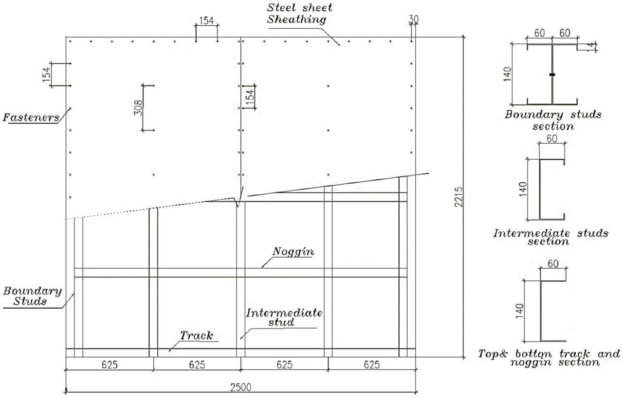
Figure 1:
The wall configuration
2.2. Test Setup
Figures 2 and 3 show the test setup. As shown in Figures, the tested specimens were connected to a base beam, which was attached to the test rigid beam using twenty four high strength mechanical bolts with 20mm diameter placed every 200mm and then anchored to the concrete floor. A lateral load was applied at the top of the specimen through a UPN 160 loading beam, attached to the upper track of the shear wall. To avoid plate bearing, pre-drilled 600 × 100 × 25mm steel plates were positioned inside the tracks aligning with the fastener holes. Hold-down was utilized to connect the web of the two end stud to the test rigid beam and to prevent uplift failure of the wall. Lateral supports were provided to prevent the out-of-plane movement of the walls.
A 500kN capacity hydraulic jack was utilized to apply the lateral load. The jack applies load directly to the loading beam. All loading during the test was conducted under monotonic displacement loading protocol with rate 2mm/sec. The load was measured at each step of loading by means of the load cell attaching with the hydraulic jack. Loading continued until the specimen experienced significant load degradation.
Three Linear Variable Differential Transformer [LVDTs] were installed to detect the different displacements of the CFS wall during the tests. Two LVDTs with a 50mm stroke were positioned near the base of the two end studs to monitor any uplift or slip that may occur at the base due to the applied lateral load. One LVDT with stroke of 200mm was placed at the top of the CFS wall in order to monitor the lateral displacement of the wall. All the LVDTs were connected to a data-logger for automatic data acquisition at a predefined rate during the test.
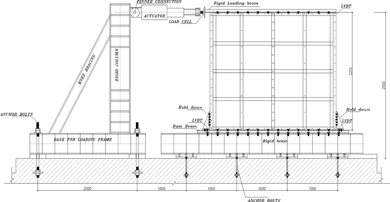
Figure 2:
Test setup schematic and arrangement of LVDTs
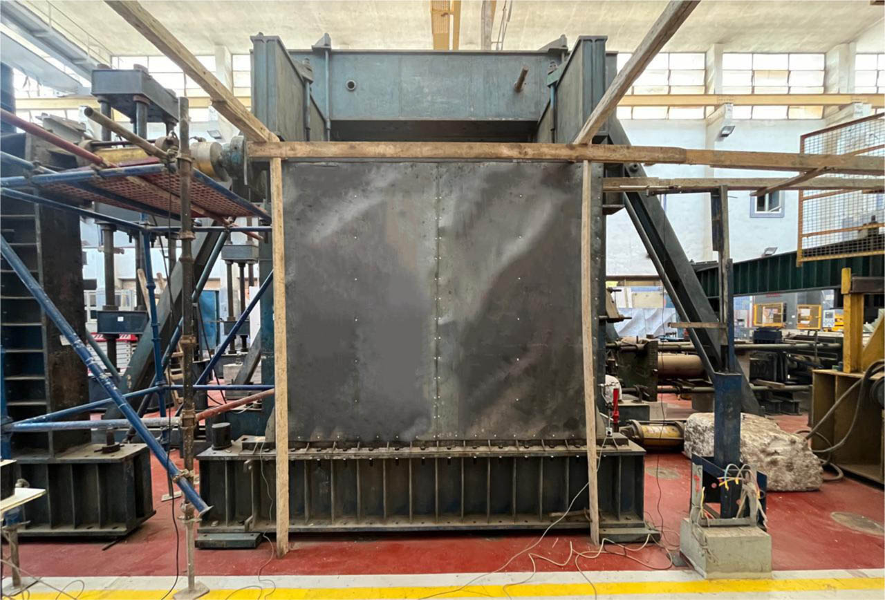
Figure 3:
Front view of the test setup
2.3. Test Results
The two tested specimens demonstrated elastic shear buckling of the sheathing material at early stages of loading. As the lateral displacement increased, the load was sustained and increased primarily due to the development of tension-field action and the post-buckling strength of the sheathing, see Figure 4-a. It was observed that the ultimate lateral load of the two specimens was mainly influenced by the failure of the sheathing to framing connections.
For the first specimen (S1), connection failures initiated by tilting of screws and hole bearing near the base of the tension end studs to sheathing connection. As the lateral displacement increased, screw pull-out from the framing occurred and the sheathing was separated from the frame at this location, see Figure 5-a. The specimen reached its maximum lateral load of 95.9kN at 41.7mm lateral displacement.
Similarly, the second specimen (S2) exhibited elastic shear buckling of the sheathing, followed by the development of tension field. The primarily failure mode was concentrated at the sheathing-to-frame connections where hole bearing and pull-over of the sheathing from the fasteners head were observed at multiple locations, see Figure 6. The primarily drop in the wall's lateral resistance was observed at a lateral displacement of 24mm. The ultimate load of this wall was about 139.2kN.
Figure 7 presents a comparison between the lateral load-displacement responses for specimens S1 and S2 under monotonic loading. Comparison reveals that the ultimate load for specimen with high strength mechanical bolts was approximately 45.15% higher than that of the specimen with self-drilling screws.
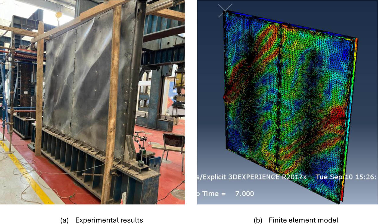
Figure 4:
Typical elastic shear buckling and tension field development
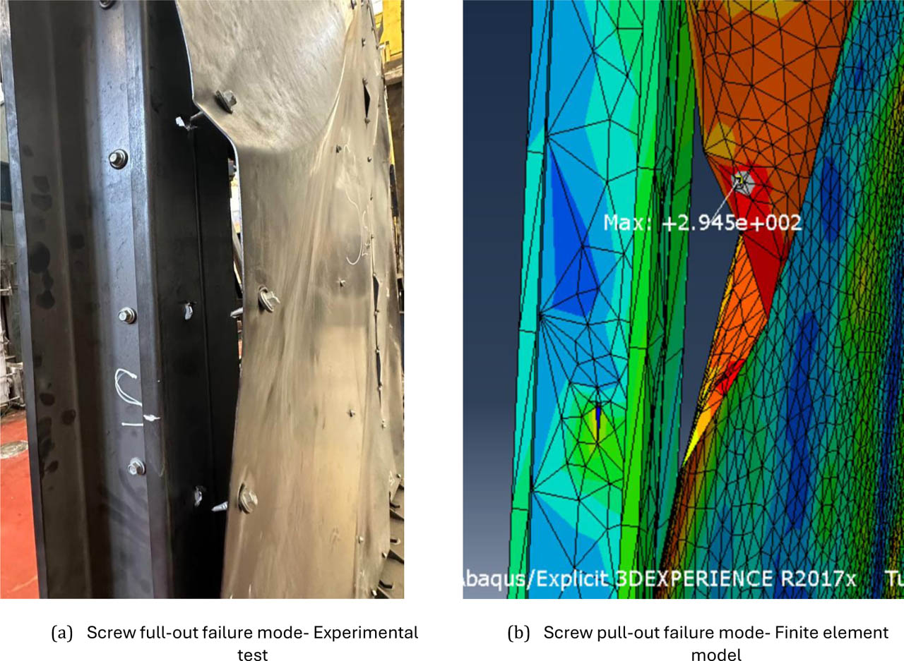
Figure 5:
Comparing of failure modes among the finite element model and the experimental results for specimen-S1
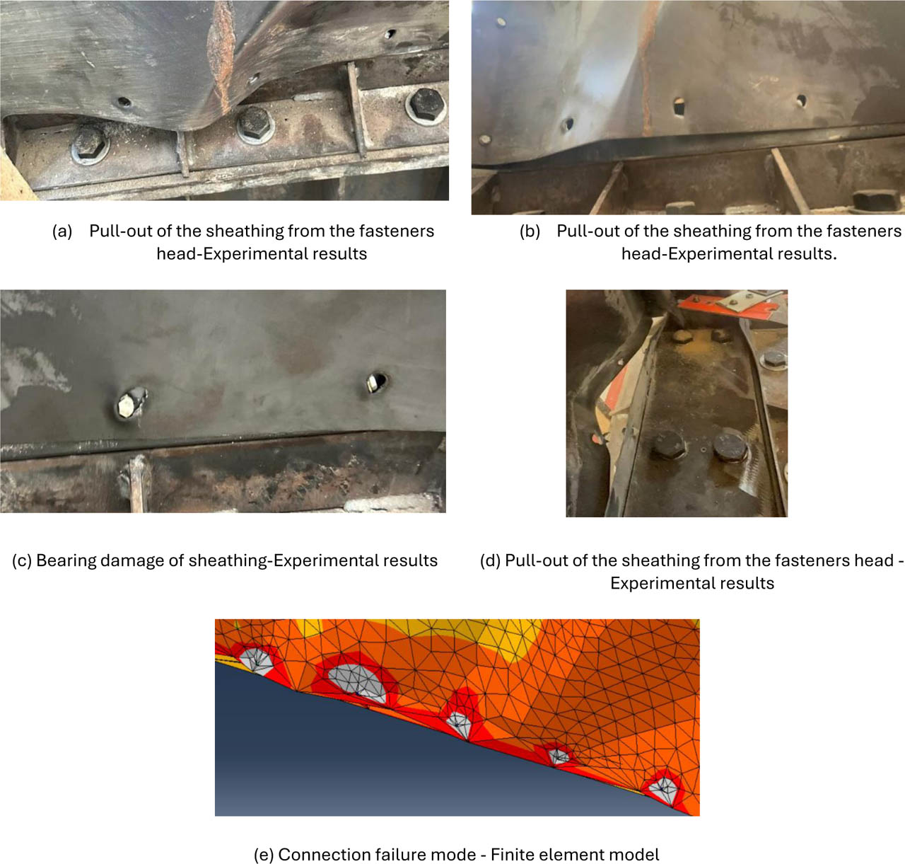
Figure 6:
Comparing of failure modes of the finite element model and the experimental results for specimen-S2
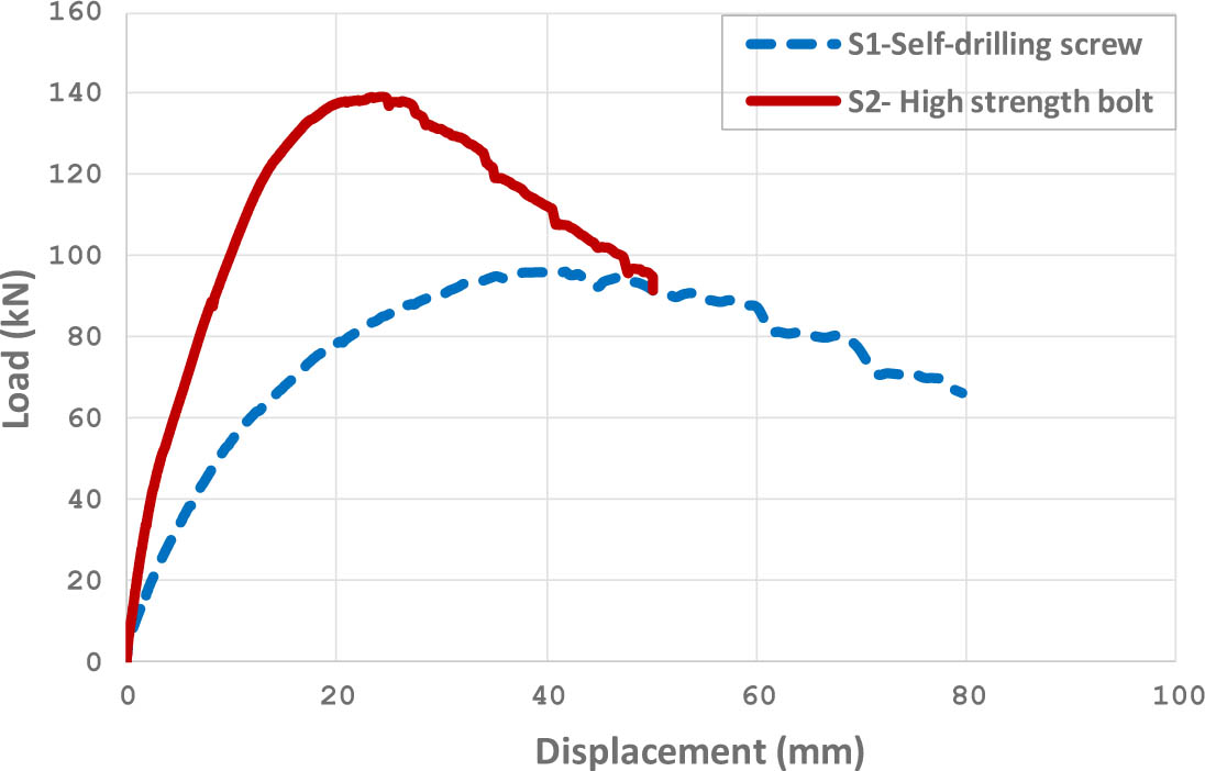
Figure 7:
Lateral load-displacement response
3. Shear Connection Test
In order to be able to represent the wall model accurately through finite element programs, a series of shear connection tests were performed to investigate the behaviour of fasteners used in CFS shear wall. Three different types of fasteners were examined; self-drilling screws with 5.2mm diameter and high strength mechanical bolts with diameters of 6 and 10mm. The tested plate thicknesses are listed in Table 1. The tests were carried out at the HBRC steel lab. The tested specimens were designed according to clause 3.2 of the European Convention for Constructional Steelwork standard ECCS TC7 TWG 7.10 (2009). The test specimens were positioned in the tensile testing machine to obtain the ultimate load and the force-displacement behaviour of one fastener connecting two steel sheets.
The force-displacement curves of the tested specimens are presented in Figures 8, 9, and 10. The results indicate that the connection with high strength bolts had significantly enhanced strength and stiffness compared to those with self-drilling screws. The experimental results were compared with the values calculated from the equations provided in the relevant design standards: Equation J4.3.1 of the American Iron and Steel Institute AISI-S100-16 standard (AISI, 2016) for self-drilling screws and Equation J3-6 of the American Institute of Steel Construction AISC-360-22 standard (AISC, 2022) for high-strength bolts. According to these design codes, the nominal strength for self-drilling screws is calculated as the minimum of: Pn=4.2 (t23d)0.5 Fu2, Pn=2.7t1d Fu1, Pn=2.7t2d Fu2. For high-strength bolts, the nominal strength is calculated as: Pn=3.0 d t Fu where t is the thicknesses of the connected members, d is the fastener diameter, and Fu is the ultimate tensile strengths of the connected members.
As shown in Table 1, a good agreement was observed between the experimental results and the values calculated using code equations. Results of these experimental tests were subsequently incorporated into the finite element model to define the connection behaviour between the steel sheathing board and cold formed steel members.
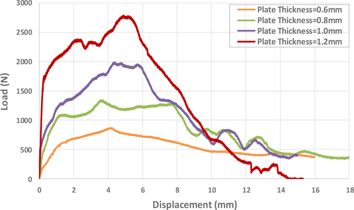
Figure 8:
Load-displacement behaviour of self-drilling screw
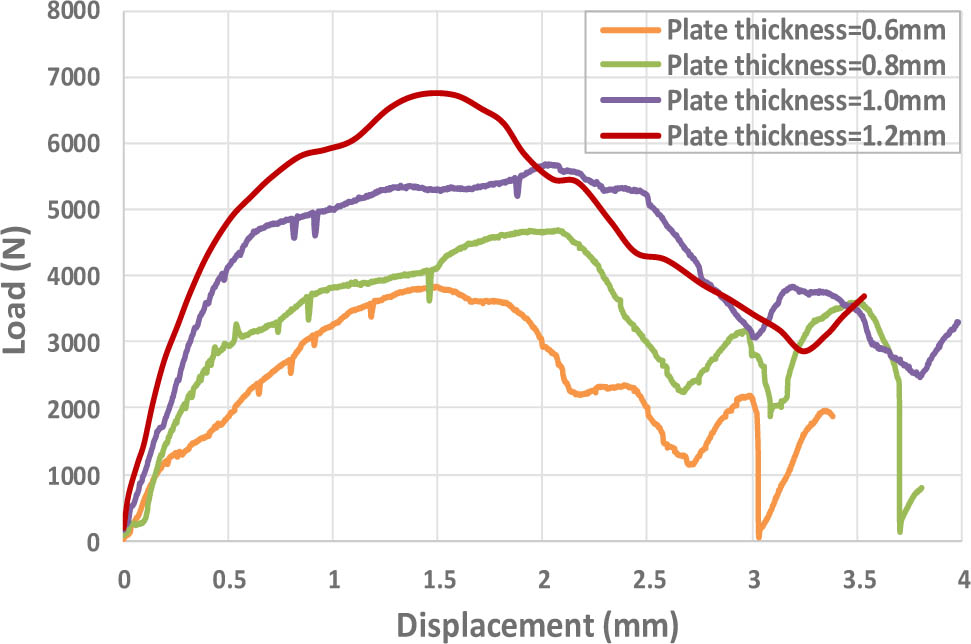
Figure 9:
Load-displacement behaviour of high strength bolt, D=6mm
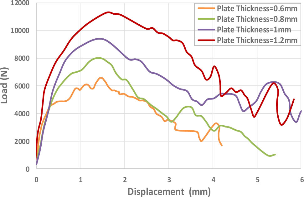
Figure 10:
Load–displacement behaviour of high strength bolt, D=10mm
Table 1:
Comparison among experimental results and calculated values according to AISI S100-16 and AISC 360-22 Standards
| Framing thickness [mm] | Sheathing thickness [mm] | Maximum strength for self-drilling screw [N] | Maximum strength for high strength bolt, D=6mm [N] | Maximum strength for high strength bolt, D=10 mm [N] | ||||||
|---|---|---|---|---|---|---|---|---|---|---|
| Experimental results | AISI-S100-16 equation | ΔF [%] | Experimental results | AISC-360 equation | ΔF [%] | Experimental results | AISC-360-22 equation | ΔF [%] | ||
| 1.5 | 0.6 | 850 | 1044.59 | 17.03 | 3800 | 3348 | 14.7 | 6520 | 5580 | 17.4 |
| 1.5 | 0.8 | 1300 | 1608.25 | 16.4 | 4700 | 4464 | 9.7 | 7990 | 7440 | 7.3 |
| 1.5 | 1.0 | 1990 | 2247.6 | 7.1 | 5600 | 5580 | 7.4 | 9550 | 9300 | 0.96 |
| 1.5 | 1.2 | 2750 | 2954.54 | 5.5 | 6700 | 6696 | 3.4 | 11400 | 11160 | 1.3 |
4. Material Properties
Coupon tension tests were performed to determine the actual properties of the material used in the tested specimens. The specimens were cut from the stud, track, and sheathing. The testing procedure was conducted according to the ASTM A370-06 standard (ASTM International, 2006). Three samples were tested for each thickness (stud/track thickness of 1.5mm, and sheathing thickness of 1mm). The average nominal yield and ultimate stresses results obtained from the coupon tests are shown in Table 2.
5. Finite Element Modelling
The commercially available software package ABAQUS/Standard (2009) was utilized in this research for simulating the finite element models. All elements, including sheathing, tracks, and studs were modelled by four node shell elements with reduced integration, type S4R. Each node has three translational and three rotational degrees of freedom. A brief parametric study on mesh size revealed that a 100mm mesh size was appropriate for modelling the track, stud, and steel sheathing. The surface to surface contact element was utilized to model the contact between the steel sheathing and surrounding studs or tracks such that separation was allowed during the analysis. The nonlinear behaviour of the cold formed steel members and the steel sheathing was simulated using an isotropic hardening model based on the von Mises yield criterion. This material model is known as “Classical metal plasticity” in ABAQUS software library. The material characteristics were defined based on the results obtained from uniaxial tension coupon tests, as listed in Table 2. In this approach, yielding is governed by the von Mises yield criterion, while the isotropic hardening rule assumes that the yield surface expands uniformly with increasing plastic strain, thus capturing the strain-hardening behaviour of steel. This approach provides a realistic representation of the stress-strain relationship under monotonic loading conditions, which is consistent with the experimental observations for cold-formed steel materials. The fastener connections were modelled using the Cartesian-Cardan Connector element existing in ABAQUS software library. The connector element properties were defined using load-displacement curves obtained from experimental shear connection tests, (see Figures 8, 9 and 10). Connector elements offer a more efficient and practical approach for representing fastener behaviour as they allow direct input of nonlinear load-displacement response of fasteners behaviour based on experimental data. Additionally, the connector force output allows for extracting force applied to the fasteners during analysis.
To represent the boundary conditions of the tested specimens in the finite element modelling, the web of the bottom track was fully constrained in all displacement and rotation degrees of freedom along the x, y, and z directions to simulate the fixation of bolts connecting the shear wall to the test rigid beam. The out-of-plane supports of the tested specimens were modelled by restraining the top track against the translation in the out of plane direction. A Monotonic pushover analysis was performed using displacement control mode, where the structural displacement was gradually increased based on a predefined time and total number of increments. The full Newton-Raphson method was utilized to solve the nonlinear equations. An automatic stabilization factor with a damping coefficient of 5.0E-4 was adopted to simplify the convergence. Figure 11 shows the finite element model of steel sheathed CFS shear wall.
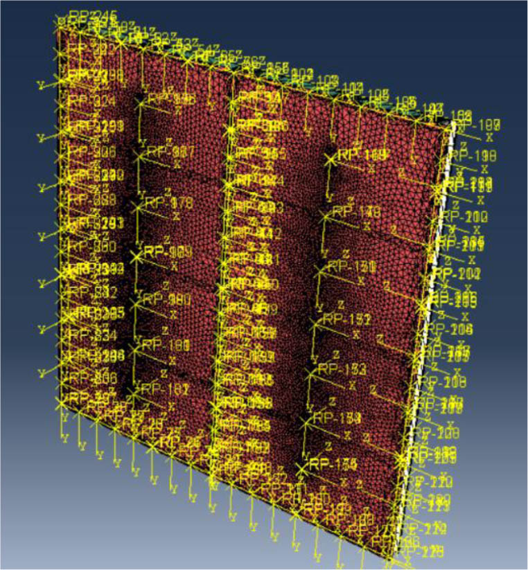
Figure 11:
Finite element model of steel sheathed CFS shear wall
6. Verification of the Finite Element Model
Verification of the finite element model was applied on two cases:
Case-1: Verification of experimental results of Specimen S1 and S2.
Case-2: Verification of previous experimental results of steel sheathed cold-formed steel shear wall.
6.1. Case-1: Verification of Specimen S1 and S2
The tested specimens were analysed, and the experimental results were used to validate the accuracy of the presented finite element model. A comparison between the results obtained from the finite element modelling and those obtained experimentally is presented in Figure 12 and listed in Table 3 as well. The comparison demonstrates that the finite element results were in reasonable agreement with the experimental results. Additionally, Figures 4, 5, and 6 compares the failure modes obtained from the finite element modelling and those observed during the experimental tests for specimens S1 and S2. The comparison reveals that the finite element model successfully captured the same failure modes as those observed experimentally for both specimens. This confirms the applicability of the finite element model in simulating the performance of CFS shear walls.
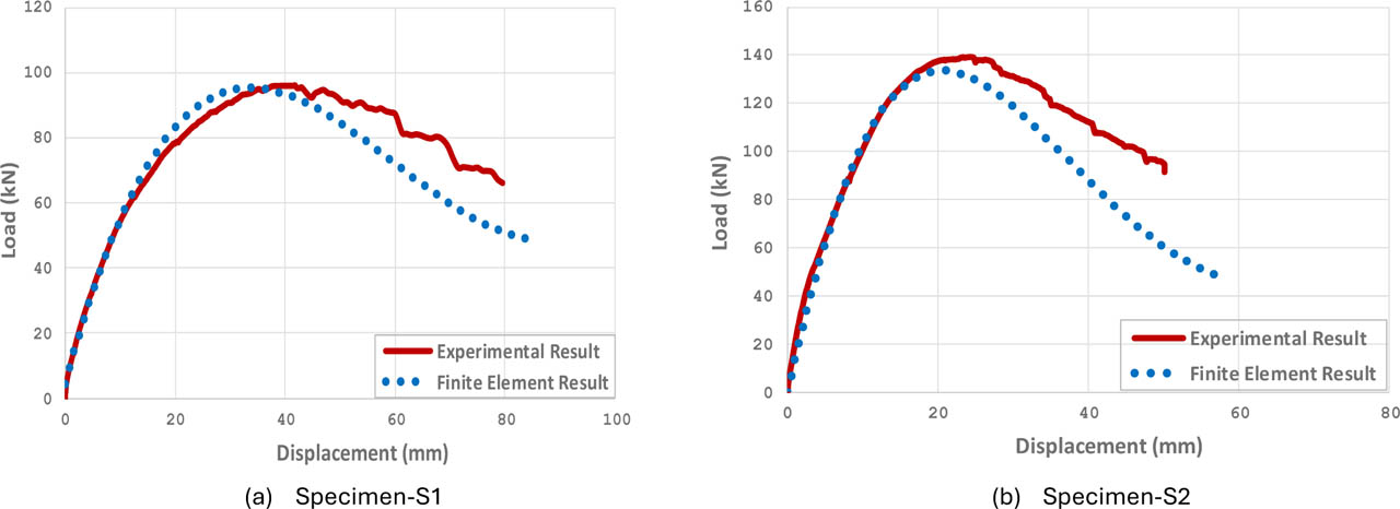
Figure 12:
Comparison among finite element results and the experimental results
6.2. Case 2: Verification of Previous Experimental Results of Steel sheathed CFS shear wall
To further validate the accuracy of the presented finite element model, wall specimens from the experimental studies performed by Yu and Chen (2009), Balh (2010), Rizk (2018), and Yu et al. (2007) were selected and numerically modelled. Complete details of these specimens can be found in the corresponding studies. Notably, the same notation used for the wall specimens in the experimental studies was adopted herein for consistency.
Table 4 summarizes the dimensions of the selected specimens and presents a detailed comparison between the experimental results and those obtained from the finite element analysis. Additionally, Figure 13 presents a comparison between the finite element and the experimental results. The comparison demonstrates good agreement, particularly in terms of initial stiffness, ultimate shear strength, and corresponding displacement. This close agreement confirms the accuracy and reliability of the presented finite element model in simulating the shear wall's structural response with high confidence.
Table 4:
Comparison among experimental results and finite element results
| Test label | Experimental results | Finite element results | ΔF (%) | Δu (%) | |||
|---|---|---|---|---|---|---|---|
| Shear strength strength (kN/m) | Displacement (mm) | Shear strength (kN/m) | Displacement (mm) | ||||
| Models Tested by Yu and Chen (2009) | 8×2×350-33×27-2 | 13.3 | 54.6 | 14 | 51.8 | 5.3 | 5.1 |
| 8×2×350-33×27-6 | 8.3 | 67.8 | 8.8 | 71.4 | 6 | 5.3 | |
| 8×6×350-43×30-2-B | 18.1 | 37.8 | 17.7 | 34.9 | 2.2 | 7.7 | |
| 8×4×350-33×17-6 | 7.6 | 33 | 7.5 | 35.8 | 1.3 | 8.5 | |
| 8×6×350-54×33-2-B | 24.8 | 34 | 25.8 | 32.3 | 4 | 5 | |
| 8×2×350-43×33-2-C | 23.4 | 55.9 | 24.2 | 52.2 | 3.4 | 6.6 | |
| 8×4×350-43×33-2-C | 22.9 | 32.8 | 23.9 | 32.3 | 4.4 | 1.5 | |
| 8×6×350-43×33-2-C | 22.3 | 27.9 | 24.7 | 29.2 | 10.8 | 4.7 | |
| 8×6×350-43×30-2-C | 19.6 | 35.8 | 19 | 35.6 | 3.1 | 0.6 | |
| 8×6×350-54×33-2-C | 29 | 39.6 | 30.7 | 39.9 | 5.9 | 0.8 | |
| 8-6-600-43-33-2-C | 21.5 | 25.7 | 21.2 | 23.9 | 1.4 | 7 | |
| 8-6-350-43-27-2-D | 21.4 | 36.1 | 21.4 | 38.2 | 0 | 5.8 | |
| Models Tested by Balh (2010) | Configuration-1 | 6.6 | 33.1 | 6.8 | 30 | 3 | 9.4 |
| Configuration-2 | 10.8 | 38.6 | 11.1 | 40 | 2.8 | 3.6 | |
| Configuration-3 | 5.9 | 29 | 5.9 | 27.5 | 0 | 5.2 | |
| Configuration-8 | 13 | 65.3 | 13.1 | 60 | 0.8 | 8.1 | |
| Configuration-9 | 15.7 | 53.1 | 15.7 | 49.9 | 0 | 6 | |
| Configuration-10 | 10.5 | 44.2 | 10.3 | 46 | 1.9 | 4.1 | |
| Configuration-11 | 15.3 | 25.8 | 15 | 24 | 2 | 7 | |
| Configuration-18 | 9.2 | 33.2 | 9.8 | 30.8 | 6.5 | 7.2 | |
| Models tested by Rizk (2018) | W1 | 36.7 | 41.7 | 37.2 | 39.2 | 1.4 | 6 |
| W2 | 40.4 | 48.3 | 41 | 45.2 | 1.5 | 6.4 | |
| W3 | 36 | 79.8 | 38.7 | 81.2 | 7.5 | 1.8 | |
| W4 | 30 | 71.1 | 32.2 | 75 | 7.3 | 5.5 | |
| W5 | 26.7 | 69.2 | 28.6 | 70 | 7.1 | 1.2 | |
| W6 | 19.6 | 58 | 19.3 | 56 | 1.5 | 3.4 | |
| W7 | 33.5 | 29.5 | 32.5 | 30 | 3 | 1.7 | |
| W8 | 29.2 | 35.4 | 30.2 | 35 | 3.4 | 1.1 | |
| W9 | 25.7 | 40.2 | 27.1 | 39 | 5.4 | 3 | |
| W10 | 20.5 | 29.1 | 20.4 | 30 | 0.5 | 3.1 | |
| W11 | 35.2 | 36.8 | 38.1 | 35 | 8.2 | 4.9 | |
| W12 | 30.2 | 31.9 | 30.8 | 30 | 2 | 6 | |
| W13 | 24.8 | 29.6 | 25.2 | 27.8 | 1.6 | 6.1 | |
| W14 | 19.2 | 28.4 | 19.9 | 27 | 3.6 | 4.9 | |
| Models tested by Cheng Yu et al. (2007) | 4×8×43×33-6/12 | 16.4 | 43.7 | 16.8 | 45 | 2.4 | 3 |
| 4×8×43×33-4/12 | 17.6 | 41.9 | 17.4 | 41.1 | 1.1 | 1.9 | |
| 4×8×43×33-2/12 | 20.1 | 41.9 | 20.4 | 38.8 | 1.5 | 7.4 | |
| 4×8×43×30-6/12 | 13.1 | 48.8 | 12.8 | 51.8 | 2.3 | 6.1 | |
| 4×8×43×30-4/12 | 14.3 | 50.3 | 14.2 | 49.3 | 0.7 | 2 | |
| 4×8×43×30-2/12 | 15 | 45 | 15.3 | 47.3 | 2 | 5.1 | |
| 4×8×33×27-6/12 | 9.5 | 39.1 | 10.2 | 40.4 | 7.4 | 3.3 | |
| 4×8×33×27-4/12 | 10 | 31 | 9.6 | 32.8 | 4 | 5.8 | |
| 4×8×33×27-2/12 | 11.9 | 43.2 | 12.1 | 41.4 | 1.7 | 4.2 | |
| 2×8×43×33-6 | 15.5 | 79.5 | 16.1 | 80.3 | 3.9 | 1 | |
| 2×8×43×33-4 | 16.7 | 66.8 | 16.6 | 69.9 | 0.6 | 4.6 | |
| 2×8×43×33-2 | 19.5 | 75.9 | 19.3 | 71.8 | 1 | 5.4 | |
| 2×8×43×30-6 | 13 | 86.4 | 13 | 87.6 | 0 | 1.4 | |
| 2×8×43×30-4 | 14.1 | 78.5 | 14.3 | 78 | 1.4 | 0.6 | |
| 2×8×43×30-2 | 16 | 75.2 | 16.3 | 71.9 | 1.9 | 4.4 | |
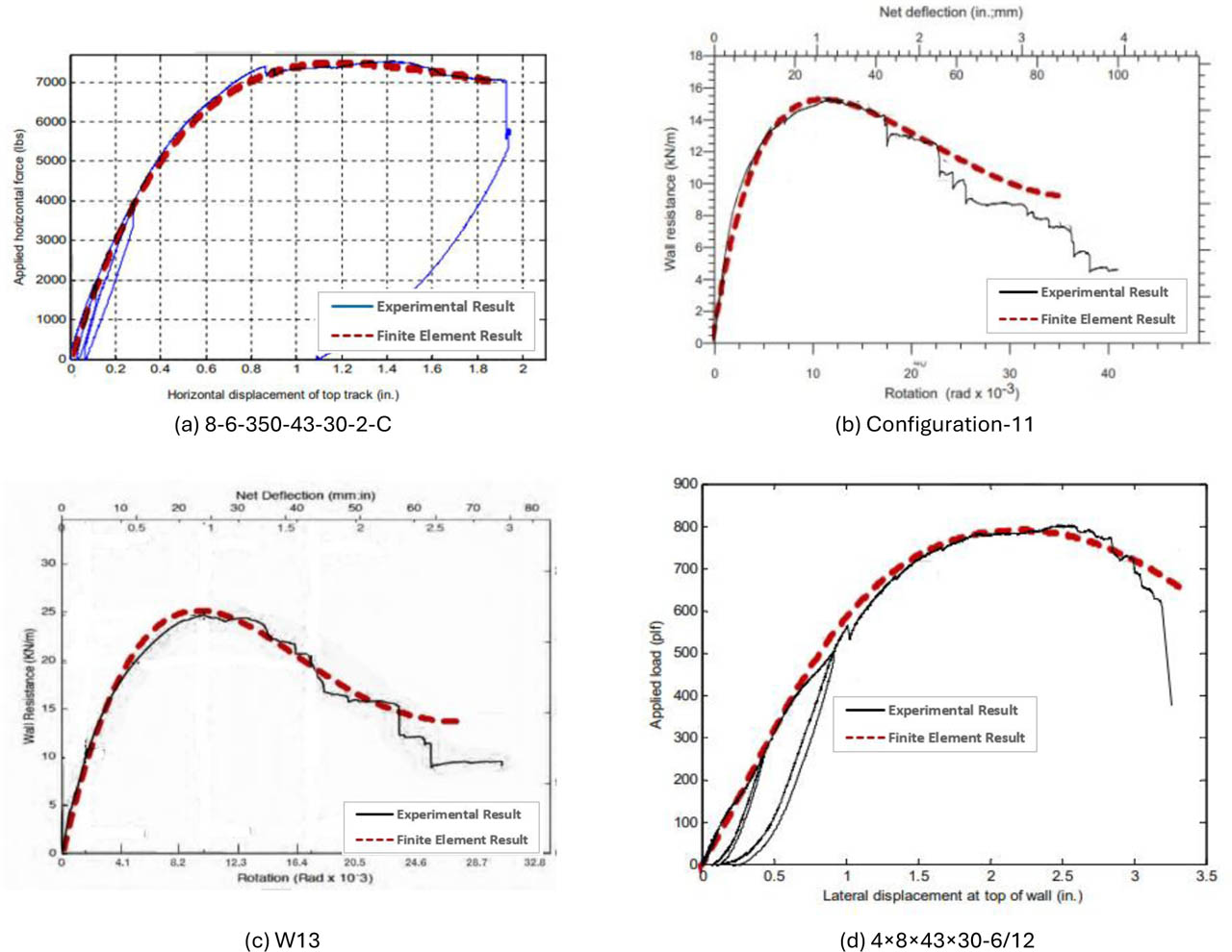
Figure 13:
Comparison of lateral load–displacement curves among finite element results and experimental results
7. Parametric Study
A parametric study was carried out to predict the behaviour of steel-sheathed CFS shear walls with various parameters including fastener spacing, thickness of sheathed steel plates, and wall width. The studied parameters are presented in Table 5. The height of the shear wall was 2500mm. All the cold formed steel framing members were 1.5mm thickness. Each shear wall panel configuration was analysed using four different types of fasteners to connect the steel sheathing board to the surrounding studs and tracks. Fasteners types include self-drilling screws with diameter 5.2mm and high-strength bolts with diameters 6, 10, and 12mm. Two hundred and forty wall configurations were included in the parametric study.
8. Discussion of Results
In this section, the results of the shear wall panel with a 0.6mm sheathing thickness, 100mm fastener spacing, and a width of 1875mm were presented. The lateral load–displacement response and the connectors force output were discussed.
8.1. Lateral load-Displacement Response
Figure 14 shows the lateral load-displacement response of the shear wall panel using four different types of fasteners. The results indicate that the ultimate strength of the cold formed steel (CFS) shear wall utilizing self-drilling screws was 35kN, with a failure mode mainly occurring at the fastener connections between cold formed steel members and the steel sheathing, Figure 15-a. By enhancement the connection strength through the use of 6mm high-strength bolts (HSB) instead of self-drilling screws, the ultimate strength improved by 132% compared to the strength using self-drilling screws. This improvement can be attributed to the fact that the failure mode was concentrated at the fastener connection, accordingly enhancing fastener strength significantly increase the overall strength of the wall. Also, the use of 10mm high-strength bolts provided an additional 43% increase in the ultimate strength over the 6 mm high strength bolts. It's worth noting that, 10mm high-strength bolts provided sufficient strength for the fastener connection. Therefore, no further enhancement in the connection strength was necessary. The use of 12mm high strength bolts did not result in any additional increase in the ultimate strength of the wall.
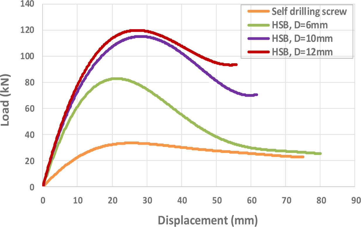
Figure 14:
Lateral load-displacement response
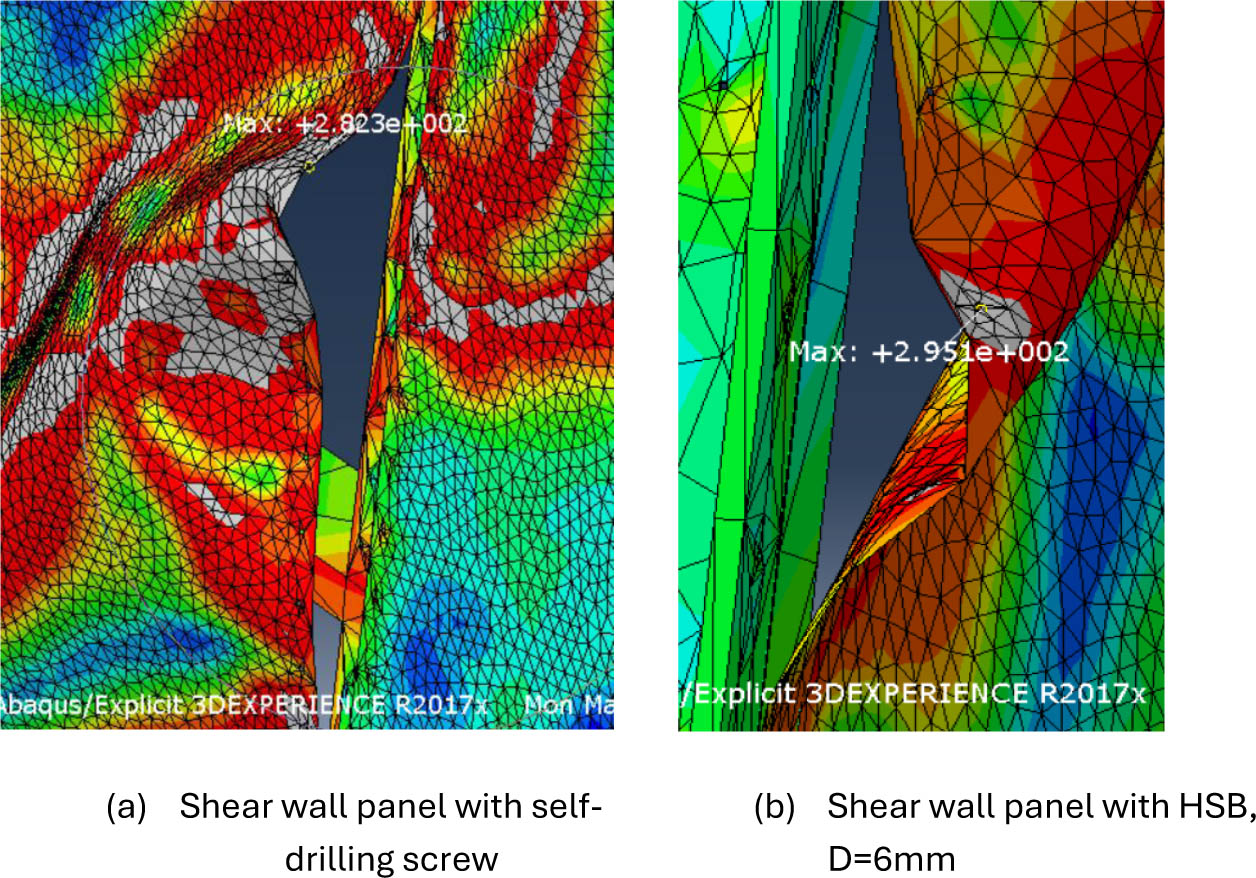
Figure 15:
Failure mode of the shear wall panel
8.2. Connectors Force Output
Figure 16 shows the connectors force output for the shear wall panel, illustrating the forces exerted on all fasteners within the model due to the development of tension field action in the steel sheathing. It was observed from the figure that the maximum force applied to the fasteners was 5542.3N. For comparison purpose, Table 6 summarizes the maximum fastener force obtained from the connector force output in the finite element model, along with the actual fastener strength obtained from shear connection tests (see Figures 8, 9, and 10), for the four fastener types used.
The comparison of the values in the table confirms that 10mm high-strength bolts were adequate to provide sufficient strength for the fastener connection as the actual fastener strength was 6520N which is greater than the maximum force applied to fasteners due to the development of tension field action in the steel sheathing (5542.3N). The use of self-drilling screws or 6mm high strength bolts led to early failure of the connection, which significantly reduced the ultimate load supported by the wall. In addition, the use of 12mm high strength bolt did not enhance the ultimate strength of the wall beyond that achieved using 10mm high-strength bolts.
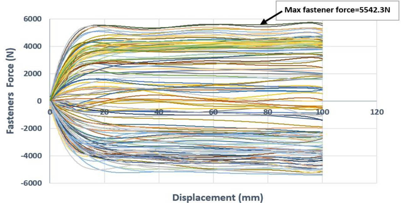
Figure 16:
Connectors force output for the shear wall panel with10mm HSB
Table 6:
Connectors force output for the shear wall panel utilizing four different fasteners type
| Shear wall panel with self-drilling screw | Shear wall panel with HSB, D=6mm | Shear wall panel with HSB, D=10mm | Shear wall panel with HSB, D=12mm | ||||||||
|---|---|---|---|---|---|---|---|---|---|---|---|
| Fastener strength a [N] | Max. fastener force b [N] | Connection failure | Fastener strength [N] | Max. fastener force [N] | Connection failure | Fastener strength [N] | Max. fastener force [N] | Connection failure | Fastener strength [N] | Max. fastener force [N] | Connection failure |
| 850 | 850 | ✓ | 3800 | 3800 | ✓ | 6520 | 5542.3 | ✗ | 7600 | 5542.3 | ✗ |
9. Effect of Fastener Spacing
The effect of fastener spacing on the lateral performance of steel-sheathed cold-formed steel (CFS) shear walls was investigated by evaluating its effect on both the ultimate lateral load and the maximum fastener force. Fastener spacing varying from 50mm to 150mm were considered.
9.1. Ultimate Lateral Load
The results shown in Figure 17 indicate that increasing the fastener spacing reduces the ultimate strength of CFS shear walls. This reduction is primarily attributed to the fact that the shear strength of CFS shear walls primarily influenced by the strength of the sheathing-to-framing connections. As the fastener spacing increases, the lateral load was distributed along fewer number of fasteners. Accordingly, larger force was transmitted to each individual fastener leading to early failure in the fastener connections.
For walls with closer fastener spacing (50mm), it was observed that 6mm high strength bolts were adequate to provide sufficient strength for the fastener connection, with additional increase in the ultimate strength by 108% compared to the strength using self-drilling screws. Further increase in the fastener strength did not affect the ultimate strength of CFS shear wall, as observed by using 10 and 12mm high strength bolts.
For walls with wider fastener spacing (150mm), due to the increased force in each fastener, 12mm high strength bolts were required to provide sufficient strength for the fastener connection with additional increase in the ultimate strength by 223% compared to the strength using self-drilling screws.
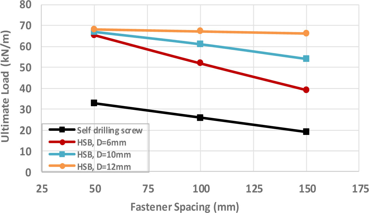
Figure 17:
Effect of fastener spacing on the ultimate load of steel sheathed shear wall, shear wall panel with 0.8mm sheathing thickness and 1875mm width
9.2. Connectors Force Output
The results shown in Figure 18 confirm that increasing the fastener spacing increases the maximum forces applied to fasteners due to the development of tension field action in the steel sheathing. Table 7 summarizes the maximum fastener force obtained from the connector force output in the finite element model, along with the actual fastener strength obtained from experimental shear connection test (see Figures 8, 9, and 10), for the four fastener types used.
The comparison of the values in the table indicates that, for walls with smaller fastener spacing (50mm), 6mm high strength bolts were adequate to provide sufficient strength for the fastener connection as the actual fastener strength was (4700N) which is greater than the maximum force applied to the fasteners (3264.3N). The use of self-drilling screws led to early failure of the connection. In addition, the use of 10 and 12mm high strength bolts did not enhance the ultimate strength of the wall beyond that achieved using 6mm high-strength bolts.
In contrast, for walls with larger fastener spacing (150mm), due to the increased force in each fastener, 12mm high strength bolts were essential to ensure sufficient connection strength as the actual strength was 9400N which is greater than the maximum force applied to the fasteners (8990.5N). The use of self-drilling screw or 6mm and 10mm high strength bolts led to early failure of the fastener connection.
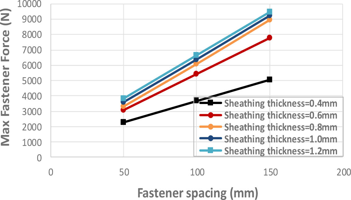
Figure 18:
Effect of fastener spacing on the maximum fastener force, shear wall panel with 1875mm width, and 12mm HSB
Table 7:
Connectors force output for the shear wall panel with 0.8mm sheathing thickness and 1875mm width under different fastener spacing
| Fastener spacing [mm] | Shear wall panel with self-drilling screw | Shear wall panel with HSB, D=6mm | Shear wall panel with HSB, D=10mm | Shear wall panel with HSB, D=12mm | ||||||||
|---|---|---|---|---|---|---|---|---|---|---|---|---|
| Fastener strength a [N] | Max. fastener force b [N] | Connection failure | Fastener strength [N] | Max. fastener force [N] | Connection failure | Fastener strength [N] | Max. fastener force [N] | Connection failure | Fastener strength [N] | Max. fastener force [N] | Connection failure | |
| 50 | 1300 | 1300 | ✓ | 4700 | 3264.3 | ✗ | 7990 | 3264.3 | ✗ | 9400 | 3264.3 | ✗ |
| 100 | 1300 | 1300 | ✓ | 4700 | 4700 | ✓ | 7990 | 5986.1 | ✗ | 9400 | 5986.1 | ✗ |
| 150 | 1300 | 1300 | ✓ | 4700 | 4700 | ✓ | 7990 | 7990 | ✓ | 9400 | 8990.5 | ✗ |
10. Effect of Sheathing Thickness
The effect of steel sheathing thickness on the lateral performance of steel-sheathed cold-formed steel (CFS) shear walls was investigated by evaluating its effect on both the ultimate lateral load and the maximum fastener force. Sheathing thickness varying from 0.4mm to 1.2mm were considered.
10.1. Ultimate Lateral Load
The results shown in Figure 19 indicate that increasing the thickness of the steel sheathing improves the ultimate strength of CFS shear wall. This improvement was primarily attributed to the fact that the shear strength of CFS walls primarily influenced by the strength of the sheathing-to-framing connections, which typically failed by bearing distortion of the sheathing material. As the sheathing thickness increases, the bearing resistance of the sheathing material increased, allowing the connections to resist higher lateral loads.
As depicted in Figure 19, the use of 6mm high-strength bolts improved the ultimate strength of CFS shear wall by 130% on average compared to the strength using self-drilling screws, as the failure mode primarily related to the fastener connection. Also, the use of 10mm high-strength bolts provided an additional 38% increase in ultimate strength over the 6mm high strength bolts, demonstrating that 10mm high strength bolts provided sufficient strength for the fastener connection. Further enhancements in the fastener strength no longer affected the ultimate strength of CFS shear wall as observed by using 12mm high strength bolts.
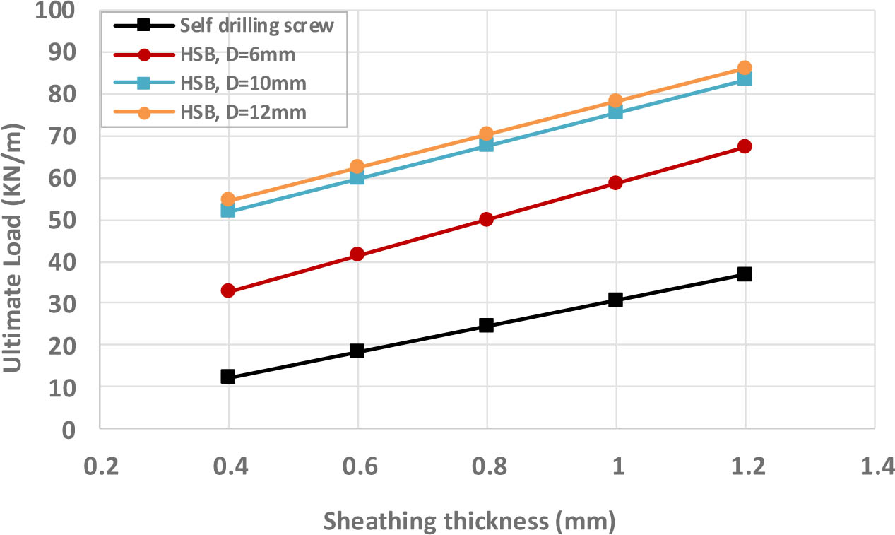
Figure 19:
Effect of sheathing thickness on the ultimate load of steel-sheathed shear wall, shear wall panel with 100mm fastener spacing and 2500mm width
10.2. Connector Force Output
The results shown in Figure 20 indicate that increasing the thickness of the steel sheathing increases the maximum force applied to the fasteners due to the development of tension field action in the steel sheathing. This was attributed to the greater resistance of the wall which results in larger forces being transmitted to each individual fastener. Table 8 presents the maximum fastener forces obtained from the connector force output in the finite element model, along with the actual fasteners strength obtained from experimental shear connection tests (see Figures 8, 9, and 10), for the four fastener types used. The comparison of the values in the table indicates that 10mm high strength bolts were adequate to provide sufficient strength for the fastener connection, as the actual fastener strength was greater than the maximum force applied to fasteners due to the development of tension field action. The use of self-drilling screws or 6mm high strength bolts led to early failure of the fastener connection. In addition, the use of 12mm high strength bolts did not enhance the ultimate strength of the wall beyond that achieved using 10mm high-strength bolts.
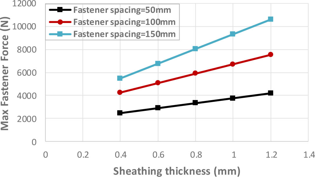
Figure 20:
Effect of sheathing thickness on the maximum fastener force, shear wall panel with 2500mm width, and 10mm HSB
Table 8:
Connectors force output for the shear wall panel with 100mm fastener spacing and 2500mm width under different sheathing thickness
| Fastener spacing [mm] | Shear wall panel with self-drilling screw | Shear wall panel with HSB, D=6mm | Shear wall panel with HSB, D=10mm | Shear wall panel with HSB, D=12mm | ||||||||
|---|---|---|---|---|---|---|---|---|---|---|---|---|
| Fastener strength a [N] | Max. fastener force b [N] | Connection failure | Fastener strength [N] | Max. fastener force [N] | Connection failure | Fastener strength [N] | Max. fastener force [N] | Connection failure | Fastener strength [N] | Max. fastener force [N] | Connection failure | |
| 0.4 | 600 | 600 | ✓ | 2500 | 2500 | ✓ | 4500 | 3698.8 | ✗ | 5200 | 3698.8 | ✗ |
| 0.6 | 850 | 850 | ✓ | 3800 | 3800 | ✓ | 6520 | 5727.5 | ✗ | 7600 | 5727.5 | ✗ |
| 0.8 | 1300 | 1300 | ✓ | 4700 | 4700 | ✓ | 7990 | 6260.8 | ✗ | 9400 | 6260.8 | ✗ |
| 1.0 | 1990 | 1990 | ✓ | 5600 | 5600 | ✓ | 9550 | 6421.5 | ✗ | 11200 | 6421.5 | ✗ |
| 1.2 | 2750 | 2750 | ✓ | 6700 | 6700 | ✓ | 11400 | 7436.9 | ✗ | 13400 | 7436.9 | ✗ |
11. Effect of Wall Width
The effect of wall width on the lateral performance of steel-sheathed cold-formed steel (CFS) shear walls was investigated by evaluating its effect on both the ultimate lateral load and the maximum fastener force. Wall width varying from 625mm to 2500mm were considered.
11.1. Ultimate Lateral Load
The results shown in Figure 21 indicate that, for walls with self-drilling screws, the resistance of the wall decreases with increasing wall width. However, for walls with high strength bolts, the resistance of the wall improves with increasing wall width due to the enhanced connection strength.
As depicted in Figure 21, the use of 6mm high strength bolts improves the ultimate strength of CFS shear wall by 80% on average compared to the strength using self-drilling screws. Also it was observed that the use of 6mm high strength bolts provided sufficient strength for the fastener connection. Further enhancements in the fastener strength did not affect the ultimate strength of CFS shear wall as observed when 10mm high strength bolts were utilized.
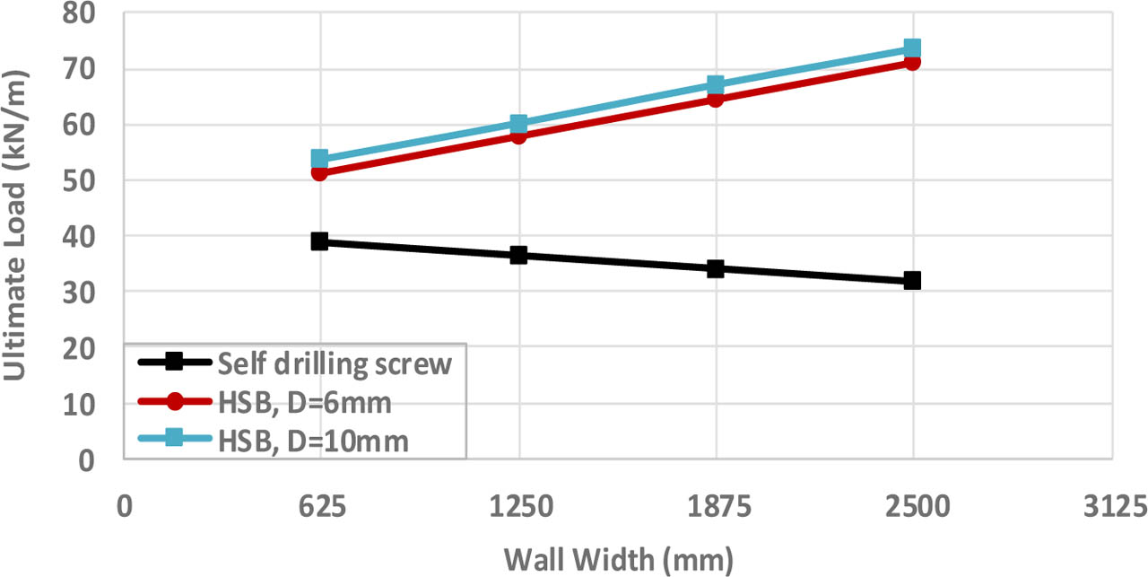
Figure 21:
Effect of wall width on the ultimate load of steel-sheathed shear wall, shear wall panel with 0.8mm sheathing thickness and 50mm fastener spacing
11.2. Connector Force Output
The results shown in Figure 22 indicate that increasing wall width increases the maximum forces applied to the fasteners due to development of tension field action in the steel sheathing. This was attributed to the greater resistance of the wall which results in larger forces being transmitted to each individual fastener. Table 9 presents the maximum fastener forces obtained from the connector force output in the finite element model, along with the actual fasteners strength obtained from experimental shear connection tests (see Figures 8, 9, and 10). The comparison of the values in the table indicates that 6mm high strength bolts were adequate to provide sufficient strength for the fastener connection, as the actual fastener strength was greater than the maximum force applied to the fasteners due to development of tension field action. The use of self-drilling screws led to early failure of the fastener connection. In addition, the use of 10mm high strength bolts did not enhance the ultimate strength of the wall beyond that achieved using 6 mm high-strength bolts.
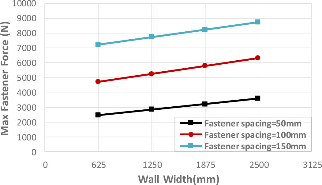
Figure 22:
Effect of wall width on the maximum fastener force, shear wall panel with 0.8mm sheathing thickness, and 6mm HSB
Table 9:
Connectors force output for the shear wall panel with 0.8mm sheathing thickness and 50mm fastener spacing under different wall width
| Wall width [mm] | Shear wall panel with self-drilling screw | Shear wall panel with HSB, D=6mm | Shear wall panel with HSB, D=10mm | ||||||
|---|---|---|---|---|---|---|---|---|---|
| Fastener strengtha [N] | Max. fastener forceb [N] | Connection failure | Fastener strength [N] | Max. fastener force [N] | Connection failure | Fastener strength [N] | Max. fastener force [N] | Connection failure | |
| 625 | 1300 | 1300 | ✓ | 4700 | 2361.6 | ✗ | 7990 | 2361.6 | ✗ |
| 1250 | 1300 | 1300 | ✓ | 4700 | 2969.3 | ✗ | 7990 | 2969.3 | ✗ |
| 1875 | 1300 | 1300 | ✓ | 4700 | 3264.3 | ✗ | 7990 | 3264.3 | ✗ |
| 2500 | 1300 | 1300 | ✓ | 4700 | 3499.05 | ✗ | 7990 | 3499.05 | ✗ |
12. Proposed Equations
A regression analysis was performed using the least squares method to analyze the connector force outputs obtained from the finite element analysis. Based on this analysis, a set of equations was proposed for calculating the maximum force applied to fasteners due to the development of tension field action in the steel sheathing. To evaluate the accuracy of each equation, the correlation coefficient (R) was calculated and presented alongside the corresponding equation. Each equation corresponds to a specific wall width. If the design involves a wall width different from those provided, interpolation between the proposed equations can be used to estimate the corresponding fastener force. These equations can guide the selection of appropriate fastener type to ensure sufficient strength for the fastener connection.
To ensure adequate design for the connection, the fastener force calculated using the proposed Equations must be less than the actual fastener strength (Pn). The actual strength of the fasteners (Pn) can be determined from the results of shear connection tests presented in Figures 8, 9, and 10, or calculated using the equations provided in the relevant design standards - Equation J4.3.1 of the AISI-S100-16 (2016) standard for self-drilling screws and Equation J3-6 of the AISC-360-22 (2022 standard for high-strength bolts.
Where:
S=Fastener spacing (mm),
t=thickness of steel sheet sheathing (mm),
Pn= actual fastener strength (N).
The proposed equations can be applied within the following range of parameters:
(a) Thickness of the steel sheet sheathing: 0.4mm to 1.2mm.
(b) Thickness of the stud, track and stud blocking: minimum 1.5mm.
(c) Fastener spacing: 50mm to 150mm.
(d) Height- to- width aspect ratio (h/w): 1:1 to 4:1.
(e) Material properties are limited to those obtained from the conducted tension coupon tests.
13. Conclusion
The primary objective of this research was to investigate the effect of connection type on the performance of cold-formed steel (CFS) shear walls sheathed with steel plates under monotonic loading through both experimental testing and finite element analysis. In this study, high-strength mechanical bolts (HSB) were used to connect the steel sheathing with the surrounding studs and tracks, and their performance was compared to that of self-drilling screws. While self-drilling screws remain the most widely adopted fasteners in the field of cold-formed thin-walled steel structures, the experimental and numerical results confirmed that high-strength bolted (HSB) connections can substantially improve the lateral strength and stiffness of CFS shear walls. In the experimental study, two wall panel specimens were tested: the first specimen with self-drilling screws used to connect the cold-formed steel members to the steel sheathing, and the other one with high-strength mechanical bolts. The results indicate that the wall panel with high-strength bolted connections had significantly enhanced shear strength and stiffness compared to the specimen with self-drilling screw connections. The ultimate load of the specimen with high-strength mechanical bolts was approximately 45% higher than that of the specimen with self-drilling screws. The tested specimens were analysed, and the experimental results were used to validate the accuracy of the presented non-linear finite element model. A parametric study was carried out to predict the behaviour of steel-sheathed CFS shear walls with various parameters including fastener spacing, thickness of sheathed steel plates, wall width, and fastener type.
Based on the findings from the parametric study, the following conclusions can be drawn:
○ Increasing the fastener spacing increases the maximum forces applied to fasteners due to the development of tension field action in the steel sheathing as the lateral load was distributed along fewer number of fasteners, resulting in larger force being transmitted to each individual fastener. Also, it was observed that increasing the fastener spacing reduces the ultimate strength of CFS shear wall, as the greater forces transmitted to fasteners lead to early failure in the fastener connections.
○ Increasing the thickness of the steel sheathing improves the ultimate strength of CFS shear wall due to the increased bearing resistance of the sheathing material. Also, it was observed that increasing the thickness of the steel sheathing increases the maximum forces applied to fasteners due to development of tension field action in the steel sheathing, as the increasing resistance of the wall results in greater forces being transmitted to each individual fastener.
○ For walls with self-drilling screws, the resistance of the wall decreases with increasing wall width. However, for walls with HSB, the resistance of the wall improves with increasing wall width due to the enhanced connection strength. Also it was observed that increasing the wall width increases the maximum forces applied to the fasteners due to development of tension field action in the steel sheathing, as the increasing resistance of the wall results in greater forces being transmitted to each individual fastener.
Since current codes and standards provide limited guidelines and criteria for designing connections in cold-formed steel sheathed shear walls, the research proposed an equation to calculate the maximum force applied to fasteners due to the development of tension field action in the steel sheathing. This equation can guide the selection of appropriate fastener type to ensure sufficient strength for the fastener connection and improving the overall lateral performance of the CFS shear walls. The research findings highlight the critical role of proper connection design in enhancing the structural performance of cold-formed steel shear wall systems, offering valuable insights for both research and practical applications in low- and mid-rise construction. However, the scope of this study was limited to monotonic loading conditions, two connection types, and steel-sheathed wall configurations. Future research should extend to cyclic and seismic loading conditions, as well as alternative sheathing materials to further validate and generalize the findings.