

Introduction
Over the past few decades, the use of advanced composite materials especially fiber-reinforced polymers (FRPs) has transformed the field of structural engineering, providing feasible solutions to increase the service life of reinforced concrete (RC) infrastructure (Spadea et al., 1998; Cosgun, 2016; Li et al., 2001). Recent studies have shown that use of CFRP can have a significant effect on delaying the onset and spread of cracks hence enhancing the serviceability and response of long-term behavior of the concrete members under different loading conditioning. In addition to the reinforcement of functions the CFRP systems are becoming a promising and an efficient means of recovery and restoration of structures having high levels of deterioration. In contrast to both conventional strengthening methods, which are mainly concerned with load-carrying capacity, CFRP retrofitting has demonstrated itself to be useful in repairs to RC members with significant damage, even those with major rebar corrosion or section loss (Kopiika et al., 2025; Kopiika et al., 2024). Although RC structures systems are common, they are prone to degradation in aggressive conditions, where corrosion of the embedded steel reinforcement increases the rate of structural degradation and escalates maintenance requirements. Carbon fiber-reinforced polymer (CFRP) has become a major solution to new construction and structural retrofitting due to its high tensile strength, low density, and outstanding corrosion resistance (Abed & Daud, 2024; Mejía et al., 2024; Agamy et al., 2025; Hamid et al., 2024; Kopiika et al., 2025). Its non-conductive, non-magnetic nature also makes it applicable in electromagnetically sensitive areas. Externally bonded FRP laminates and sheets have been shown to be superior to conventional strengthening methods of RC retrofitting, not only in terms of superior corrosion resistance and high strength-to-weight ratios, but also in terms of flexibility of application. Their manual installation facilitates customized reinforcement layouts that accommodate diverse structural geometries (Rahman et al., 2023; Bouziadi et al., 2023; Hameed & Daud, 2024; Hamoda et al., 2025; Al-Allaf et al., 2015; Azam et al., 2017; Foster et al., 2017; Lateef et al., 2024).
In line with the development of FRP technology, lightweight concrete (LWC) has become a technically and economically advantageous material in modern construction. Due to its lower density, usually 60–85% of that of normal-weight concrete (NWC) in surface-dry conditions and up to 55% less when submerged LWC can greatly reduce dead loads, thus enabling smaller foundation sizes, larger structural members without altering erection procedures, or simplified geometries without adding weight. Its buoyancy makes these properties especially useful in marine applications, including floating docks and offshore platforms. LWC also has superior fire resistance and thermal insulation; the thickness of walls can be decreased by about 20 percent compared to NWC, and heat transfer through LWC can be reduced by 20–50 percent, depending on density (Lo et al., 2007; Al-Allaf et al., 2016; Yu et al., 2015).
Since experimental studies using large-scale systems are cost-prohibitive as well as logistically infeasible, FEA has become an efficient means of modeling and evaluating the complex structural responses. FEA allows the stress fields to be simulated in detail, and crack growth initiation and propagation, and nonlinear material interactions (Al-Allaf et al., 2024). Nevertheless, great importance is placed on the accuracy of such simulations and requires careful model calibration based on experimental results or proven analytical formulations (Daud et al., 2025). Out of the platforms available, ABAQUS has been extensively used as a robust tool to model RC structures considering the strain capacity of its nonlinear solver and comprehensive definition of materials with additional features to model concrete damage plasticity and interaction with reinforcement. Another successful application of ABAQUS is flexural and shear responses of RC members subjected to different loading regimes, where the prior studies obtained good results (Sakbana & Mashreib, 2020).
However, few numerical studies addressing LWC members reinforced with CFRP are available, and most of them examine either traditional NWC components or shear and flexural behavior in the absence of examining the CFRP and concrete strength effects on externally bonded CFRP reinforcement to the full extent (Osman et al., 2018). More recent advances in FEA have permitted the increased accuracy of simulation of the shear-cracking behaviour due to optimised mesh densities, novel stress strain relations and fine-tuned dilation angles (Ma et al., 2025). The process of calibration of the numerical models against the experimental data significantly enhances the predictive accuracy of these models and diverts away the time-consuming full-scale tests and allows developing retrofitting schemes that are optimized in terms of their performance (Jumaa & Yousif, 2019; Ma et al., 2025; Tawfik et al., 2025; Bukhari et al., 2010).
Shear behavior in NWC remains a contentious subject (Mhanna et al., 2019; Waqas et al., 2025; Barros et al., 2007), with divergent design provisions worldwide reflecting differences in the perceived contribution of aggregate interlock, crack-face friction, dowel action, and stirrup resistance. The introduction of FRP further complicates standardization due to variability in composite properties and bond performance. While extensive investigations have examined FRP-strengthened NWC beams considering variables such as strengthening configuration, bond length (Ouezdou et al., 2009; Alhamad et al., 2017), shear span-to-depth ratio (Ouezdou et al., 2009; Alhamad et al., 2017), member size (Al-Rousan & Issa, 2016; Maalej & Leong, 2005), shear reinforcement ratio (Yu et al., 2015), FRP orientation and width (Jin et al., 2020; Saadoon, 2019), and loading conditions (Godat et al., 2010; Anil, 2006; Obaidat et al., 2010; Tanarslan & Altin, 2010) research on bond behavior in LWC members remains limited.
Despite the fact that much research has been done on shear behavior of reinforced concrete beams and strengthening effects of fiber-reinforced polymers, most of the studies have been done on normal-weight concrete or have concentrated more on flexural performance. Conversely, there is limited research on shear behavior of lightweight concrete (LWC) beams reinforced with CFRP reinforcement, although the use of lightweight materials in contemporary structural construction is increasingly popular where low self-weight and enhanced seismic behavior are sought. This gap in knowledge is important since LWC beams have varying cracking patterns, bond properties, and shear transfer mechanisms than normal-weight concrete. In addition, the majority of the current finite element modelling work has not been fully calibrated on shear-critical LWC members with CFRP retrofitting. To fill this gap, the current paper constructs and validates an ABAQUS finite element model of LWC beams reinforced with CFRP, which is calibrated against the experimental findings of Al-Allaf et al. 2019. Through a systematic analysis of the impact of concrete compressive strength, CFRP modulus of elasticity, and the amount of CFRP layers, the study offers new information on the interaction of these factors and their impact on ultimate shear capacity and structural ductility. The results are not only useful in the development of modelling accuracy but also provide useful design advice on the optimization of CFRP retrofitting in shear-critical LWC structures.
To address this research gap, the present study numerically investigates the local bond properties of FRP reinforcement in LWC and their influence on the shear behaviour of LWC beams. The finite element model was initially calibrated against the experimental results of Al-Allaf et al. 2019, ensuring robust predictive capability. Subsequently, a comprehensive ABAQUS-based parametric study was conducted, focusing on three primary variables: concrete compressive strength, CFRP reinforcement ratio, and the modulus of elasticity of CFRP. The outcomes provide deeper insight into the interrelationship between material properties, structural configuration, and shear resistance in LWC beams strengthened with epoxy-bonded CFRP sheets, thereby contributing to the advancement of performance-driven retrofitting strategies.
The findings have important practice and code development implications. The calibrated FEA models minimize the use of destructive full-scale testing, which simplifies the assessment of retrofit solutions. The insights produced can be used to optimize reinforcement strategies specific to strength classes and geometric profiles, and a more detailed understanding of bond and size effects can be used to make shear-critical members in bridges, high-rise buildings, and critical infrastructure safer. Finally, the work provides a basis of knowledge that can be used in future design provisions that involve bonded CFRP in environmentally sustainable concrete systems.
2. Numerical Model
2.1. Model Development and Calibration
The shear behaviour of lightweight concrete (LWC) beams reinforced with externally bonded carbon fiber-reinforced polymer (CFRP) reinforcement was simulated using a three-dimensional finite element (FE) model developed in ABAQUS/Standard. The concrete substrate was simulated by eight-node linear brick elements with reduced integration (C3D8R), which allows efficient calculation and stress-strain prediction. The Concrete Damaged Plasticity (CDP) model was used to capture its nonlinear response, such as cracking, crushing, and stiffness degradation.
Two-node truss elements (T3D2) were used to model internal steel reinforcement embedded in the concrete through the embedded region constraint, which provides full bond compatibility and was modeled as an elastic-plastic material with strain hardening. The CFRP was characterized as a linear elastic orthotropic material and simulated with four-node shell elements (S4R) with fiber orientation along the main load path to simulate tensile load transfer and possible fiber breakage. The contact between the CFRP plate and the concrete surface was defined as a cohesive contact, and the technique of cohesive surface was used, where the interaction was modeled as a contact pair with surface interaction properties. The thickness of the adhesive layer was considered to be negligibly small. The tie constraints were used to define interactions between all components to ensure compatibility of displacement until interface failure. The experimental setup of simply supported ends and shear loading was replicated as boundary conditions and nonlinear static analysis was performed using the Riks method to obtain both pre-peak and post-peak response. This modeling approach, through an appropriate selection of element types, constitutive models, and definitions of interaction, offered a powerful framework to predict load-deflection behaviour, crack propagation, and ultimate failure modes of CFRP-strengthened LWC beams.
The experimental results of Al-Allaf et al. 2019 such as load-deflection behaviour, crack propagation patterns, and ultimate shear capacity were used to calibrate the FE model developed in this study and serve as benchmark data. These results were used to adjust the material parameters and interface properties in the proposed FE models, allowing a direct and meaningful comparison between the predicted structural responses and the experimentally observed behaviour. This calibration procedure ensured that the modelling strategy was a true representation of the actual structural performance, which made it more reliable and predictive.
Al-Allaf et al. 2019 conducted an experimental programme of six simply supported reinforced concrete beams to study the shear response of LWC members strengthened with CFRP strips, and compared them with equivalent NWC beams. The total length of each beam was 2000 mm, the cross-section was 200 mm wide and 300 mm deep, the effective depth was 264 mm, and the nominal concrete cover was 28 mm. The longitudinal reinforcement was three high-yield deformed bars (16 mm diameter) at the tension face and two bars of the same diameter at the compression face, resulting in a longitudinal reinforcement ratio of about 1.67%. To ensure shear-critical behaviour, transverse reinforcement was limited to two steel stirrups positioned adjacent to each support, and the shear span-to-effective depth ratio (a/d) was set to 2.27 to promote diagonal shear cracking as the dominant failure mechanism.
All specimens were tested under displacement-controlled four-point bending. The supports were positioned 150 mm from each beam end and comprised 25 mm diameter steel rollers seated on 200 × 100 × 25 mm steel bearing plates to prevent local crushing; one support was fixed while the other was free to translate horizontally. Loading was applied through a hydraulic jack with a calibrated 500 kN load cell, transferring force via a steel spreader beam to ensure uniform load distribution. Identical roller and plate assemblies were placed under the two load application points. Vertical deflections at mid-span and near the supports were measured using three linear variable differential transformers (LVDTs) mounted on an independent reference frame to eliminate extraneous movement effects.
Two CFRP strengthening configurations were considered: U-shaped wraps (UST) and fully closed wraps (CST). In both configurations, unidirectional CFRP strips, 100 mm wide and oriented perpendicular to the beam’s longitudinal axis, were bonded using a two-part epoxy system comprising a primer and a high-strength adhesive. The strips were applied at 150 mm centre-to-centre spacing along the shear span, extending from the support region to the loading points on both beam sides. In the U-wrap configuration, CFRP was applied to the soffit and vertical sides, terminating approximately 20 mm below the compression face. In the closed-wrap configuration, CFRP strips encircled the entire cross-section to maximise confinement and anchorage length.
Before CFRP application, bonding surfaces were mechanically ground, cleaned of dust, and had all edges rounded to reduce stress concentrations. A primer coat was first applied, followed by adhesive, after which the CFRP strips were placed, pressed firmly for full contact, and rolled to expel any air voids. In closed wraps, overlaps were sealed to ensure continuous fibre alignment. All beams were cured under laboratory conditions prior to testing. The details of the experimental programme used by Al-Allaf et al. 2019; 45 to calibrate the FE models developed in this study are shown in Figure (1).
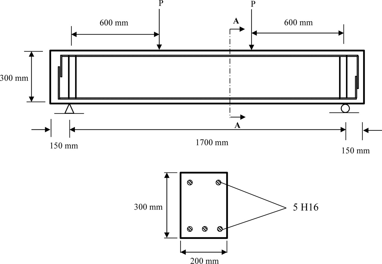
Figure 1:
Specimens details
2.2. Material Properties
The aim of the experimental programme conducted by Al-Allaf et al. 2019 was to develop a robust and complete set of material parameters of LWC, NWC, high-yield steel reinforcement, and CFRP composites. The objective was to make sure that the material performance that was observed during laboratory testing could be directly correlated with numerical simulations. The physical and mechanical properties were all measured using standard laboratory tests and the specimens were cast using the same batches as those used in the structural beam tests to ensure consistency and remove the batch-to-batch variation.
2.2.1. Concrete Mechanical Properties
Two types of concrete were investigated: a lightweight aggregate concrete (LWC) using Lytag as the coarse aggregate, and a normal weight concrete (NWC) employing crushed granite aggregate. Both concretes were proportioned to achieve the same nominal compressive strength grade, ensuring that differences in structural response were attributable primarily to density, stiffness, and tensile-related properties rather than compressive capacity.
Mechanical testing revealed that while the compressive strengths of LWC and NWC were very close, significant differences existed in other key parameters (Table 1). In particular, the modulus of elasticity of LWC was approximately 21% lower than that of NWC, indicating reduced stiffness under service loads. Similarly, the modulus of rupture a parameter directly related to the tensile performance of the concrete was around 13% lower for LWC, reflecting the weaker aggregate interlock and lower tensile capacity of lightweight aggregates. The density difference was substantial, with LWC being roughly 22.6% lighter, offering a clear advantage in reducing structural self-weight but potentially influencing dynamic behaviour and shear resistance.
Table 1:
Mechanical properties of concretes
| Type of Concrete | Concrete cube strength fcu [MPa] | Fflexural tensile of concrete fct [MPa] | Elastic modulus of concrete Ec [MPa] | Concrete density ρc [kg/m3] |
|---|---|---|---|---|
| NWC | 42.10 | 3.49 | 29860 | 2356 |
| LWC | 43.34 | 3.026 | 23510 | 1823 |
The longitudinal reinforcement consisted of high-yield deformed steel bars with a nominal diameter of 16 mm (H16). These were tested under uniaxial tension to characterise their yield strength, ultimate strength, ductility, and elastic modulus. The results, shown in Table 2, confirm that the reinforcement met the performance requirements for high-yield steel, with a high modulus of elasticity of 196 GPa, a distinct yield plateau, and substantial post-yield ductility.
Table 2:
Mechanical properties of steel reinforcement.
| Yield strength [MPa] | Yield steel strain [µm/m] | Ultimate strength [MPa] | Ultimate steel strain [µm/m] | Elastic Modulus of Steel [GPa] |
|---|---|---|---|---|
| 510 | 2600 | 650 | 130000 | 196.154 |
The shear strengthening system consisted of unidirectional CFRP sheets bonded to the concrete surface with a two-part epoxy resin system. The CFRP sheets provided a high-strength, high-stiffness reinforcement layer, while the epoxy served as both an adhesive and a stress-transfer medium between the composite and the concrete substrate. The mechanical properties of both the CFRP and the primer resin are presented in Table 3.
Table 3:
Mechanical properties of CFRP reinforcement and primer resin
| CFRP reinforcement | |
| Modulus of elasticity [GPa] | 240 |
| Tensile stress [MPa] | 4000 |
| Failure strain [%] | 1.6 |
| Primer resin (Epoxy Plus) | |
| Compressive stress [MPa] | 100 |
| Tensile stress [MPa] | 19 |
| Flexural stress [MPa] | 30 |
| Bond to concrete [MPa] | > 5.3 |
| Modulus of elasticity [GPa] | 5 |
2.3. Meshing Strategy
In the present study, the FE models were developed in ABAQUS using distinct element types to accurately simulate the different constituents of the reinforced concrete (RC) beams. The concrete body was discretised with 8-node linear brick elements with reduced integration (C3D8R), selected for their capability to capture three-dimensional stress states and minimise computational cost. The embedded longitudinal steel bars and externally bonded CFRP strips were idealised using 2-node linear truss elements (T3D2), which are well-suited for modelling uniaxial axial behaviour without bending stiffness. A mesh convergence study was performed to evaluate the influence of element size on the numerical response. Mesh densities corresponding to element sizes of 30 mm, 40 mm, and 50 mm were examined. The comparison between numerical predictions and experimental observations indicated that the 30 mm element size offered the most accurate representation of the load–deflection behaviour and the initiation and propagation of cracks. Consequently, this mesh density was adopted for all subsequent simulations. The final mesh configuration, incorporating both the solid concrete elements and truss reinforcement elements, is illustrated in Figure 2, which presents the fully discretised model used in the analysis.
2.4. Boundary Conditions and Loading Scheme
The precise definition of boundary conditions was essential to achieving realistic finite element (FE) simulations in ABAQUS. The beam model was idealised to replicate the experimental support arrangement: one end was fixed against both longitudinal (x) and vertical (y) displacements, while the opposite end was restricted only in the vertical direction (y). To represent the actual bearing mechanism observed in the laboratory tests, rectangular steel bearing plates measuring 200×100×25 mm were positioned beneath both supports. The contact between these plates and the concrete surface was modelled using a tie constraint, ensuring full compatibility of displacements and eliminating relative slip at the interface. The overall support arrangement is illustrated in Figure 2.
The loading protocol followed the experimental monotonic testing procedure and was implemented in ABAQUS through the Static General step. Loads were applied as a uniform pressure acting on the top surfaces of two steel loading plates, each of dimension’s 200×100×25 mm, positioned symmetrically along the span. The arrangement replicated the four-point bending setup used in the physical tests. The applied pressure was distributed over a contact width of 100 mm on the concrete surface, accurately representing the experimental line load application. As with the supports, a tie constraint was used to fully bond the loading plates to the surface of concrete, thereby securing uniform stress transfer and preventing local slip. The complete loading configuration is depicted in Figure 2.
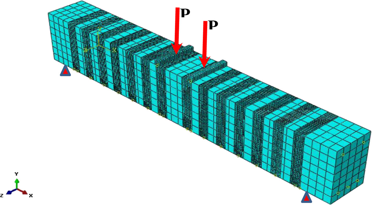
Figure 2a:
Mesh for the full numerical model
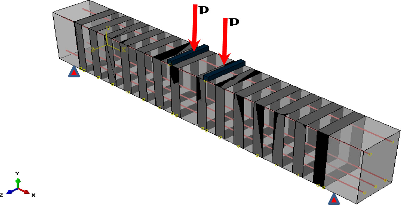
Figure 2b:
Full numerical model
3. Comparative Analysis of FEA Predictions and Experimental Results
The subsequent sections provide a comprehensive comparison between the results derived from the ABAQUS finite element analysis (FEA) and the corresponding experimental findings for all tested beam specimens. The evaluation emphasizes key performance aspects, including load–displacement response, ultimate load capacity, and the development and distribution of crack patterns.
3.1. Load–Displacement Behavior
Figures 3 to 5 illustrate the comparison between the load–displacement curves obtained from the experimental program conducted by Al-Allaf et al. (2019) and the results from the developed finite element analysis (FEA) model for lightweight concrete beams strengthened with externally bonded CFRP sheets. The evaluation encompasses all investigated configurations: unstrengthened beams (BN, BL), beams strengthened with CFRP sheets but without stirrups (BN-UST, BL-UST), and beams strengthened with both CFRP strips and continuous stirrups (BN-CST, BL-CST).
In general, the FEA model reproduced the experimental results with a high degree of accuracy over the entire range of loading, from the initial application of load to the point of ultimate failure. The numerical curves closely followed the experimental trends in terms of slope, curvature, and the transition between the elastic and nonlinear stages. In the elastic stage, the response of most beams exhibited nearly identical stiffness between the FEA and experimental results, indicating that the elastic modulus and section properties were appropriately represented in the model. As loading progressed into the nonlinear region, the FEA successfully captured the reduction in stiffness and the progressive increase in deflection, reflecting the cracking and inelastic deformation mechanisms observed in the physical tests.
Nevertheless, certain minor deviations were identified, particularly in the early stages of loading, where some FEA curves exhibited slightly higher stiffness than those recorded experimentally. This discrepancy can be largely attributed to the modeling assumption of fully bond between the CFRP sheet and substrate of the concrete, which inherently eliminates the possibility of interface slip. In the actual beams, a small degree of relative movement between the CFRP and concrete can occur under load due to adhesive imperfections, stress concentrations, or local debonding, slightly reducing stiffness. Moreover, the experimental specimens, being cast from lightweight concrete, inherently contained micro-cracks from shrinkage, as well as aggregate–mortar interfacial weaknesses, both of which reduce stiffness in practice. In contrast, the FEA model assumed a perfectly homogeneous concrete material with idealized bond behavior, thereby marginally overestimating the elastic stiffness in some cases. The strengthened beams demonstrated markedly enhanced structural performance compared to the unstrengthened specimens, a trend that was clearly evident in both the experimental and numerical datasets. For beams without stirrups, CFRP sheet or strip application significantly increased both the ultimate load capacity and the deflection at failure, indicating improvements in both strength and ductility. When combined with continuous stirrups, the CFRP strengthening provided the highest levels of load resistance and deformation capacity, delaying shear-related cracking and enhancing energy absorption before failure. The FEA predictions for these enhanced behaviors were in close agreement with the experimental findings, confirming the robustness of the adopted numerical modeling strategy.
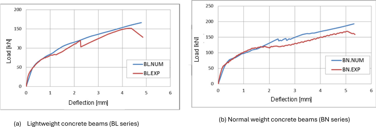
Figure 3:
Comparison of experimental and FEA load–displacement curves for un-strengthened lightweight concrete beams (BN and BL)
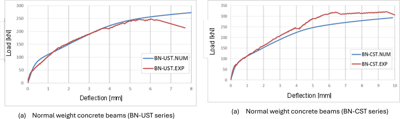
Figure 4:
Comparison of experimental and FEA load–displacement curves for CFRP-strengthened lightweight concrete beams without stirrups (BN-CST and BL-CST)
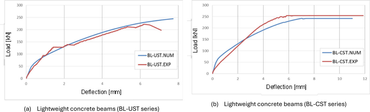
Figure 5:
Comparison of experimental and FEA load–displacement curves for CFRP-strengthened lightweight concrete beams without stirrups (BN-UST and BL-UST)
3.2. Ultimate Load Comparison
Table 4 presents a quantitative comparison between the experimentally measured ultimate loads and mid-span deflections and those predicted by the FEA model. The differences in ultimate load between the two sets of results ranged from 3.8% to 8.6%, while the corresponding differences in ultimate deflection were within 6.5% for all tested beams. Such small discrepancies are well within the typical range for nonlinear finite element simulations of reinforced and FRP-strengthened concrete structures, particularly when modeling complex interaction effects between materials.
For the unstrengthened beams, BN and BL recorded experimental ultimate loads of 167 kN and 151.36 kN, respectively. The FEA slightly overestimated these capacities, predicting values 7.2% and 8.3% higher. This pattern of slight over prediction is consistent with the stiffer elastic response noted earlier and reflects the idealized bond and material assumptions inherent to the model.
In the case of strengthened beams without stirrups, BN-UST reached an experimental ultimate load of 257.84 kN, while the FEA estimated 269.12 kN, a difference of 4.2%. Similarly, BL-UST achieved 222.38 kN experimentally, compared to 240.13 kN in the FEA, giving a 7.3% difference. These results indicate that the model effectively captured the beneficial effect of CFRP strengthening even in the absence of additional shear reinforcement, with only modest deviations from measured values.
For the beams strengthened with continuous stirrups, the gains in performance were most significant. BN-CST recorded the highest experimental ultimate load at 320 kN, with the FEA slightly underestimating at 292.32 kN (an 8.6% difference). BL-CST achieved 254.2 kN experimentally, while the FEA predicted 244.32 kN, underestimating by 3.8%. In these cases, the slight underestimation may be due to conservative assumptions in the numerical representation of combined shear and flexural resistance when both CFRP reinforcement and stirrups contribute to load carrying.
Overall, the good match between the numerical and experimental results demonstrates the accuracy and predictive capability of the proposed finite element modeling approach. The model was able to reproduce the overall load-displacement behavior, ultimate load capacity, and general deformation behavior of CFRP-strengthened lightweight concrete beams, which makes it a valid tool to be used in further parametric studies and design optimization.
Table 4:
Experimental and numerical ultimate loads and mid-span deflections of LWC and NWC beams reinforced with CFRP sheets or strips
| Name of beam | EXP. Load [kN] | NUM. Load [kN] | Difference [%] (Load) | EXP. Def. [mm] | NUM. Def.[mm] | Difference [%] (Def.) | Failure mode | |
|---|---|---|---|---|---|---|---|---|
| EXP. | NUM | |||||||
| BN | 167 | 180 | 7.2 | 5.3 | 5.32 | 0.4 | Shear | Shear |
| BL | 151.36 | 165 | 8.3 | 4.85 | 4.7 | 3.1 | Shear | Shear |
| BN-UST | 257.84 | 269.12 | 4.2 | 7.69 | 7.98 | 3.6 | Shear+CFRP debonding | Shear+CFRP debonding |
| BN-CST | 320 | 292.32 | 8.6 | 10 | 9.75 | 2.5 | Shear+CFRP rupture | Shear+CFRP rupture |
| BL-UST | 222.38 | 240.13 | 7.3 | 7.2 | 7.7 | 6.5 | Shear+CFRP debonding | Shear+CFRP debonding |
| BL-CST | 254.2 | 244.32 | 3.8 | 11.59 | 11 | 5.1 | Shear+CFRP rupture | Shear+CFRP rupture |
3.3. Failure Modes and Crack Patterns
The failure modes of the experimental specimens and the FEA predictions were found to be in general agreement, which indicates that the model can be used to simulate the physical behavior of LWC beams strengthened with CFRP reinforcement. The main failure modes observed in the tested specimens were diagonal shear cracking, CFRP debonding, and CFRP rupture, depending on the reinforcement pattern and loading conditions.
In the case of the control beam (BN), the failure was described by the development and extending of diagonal shear cracks that started at the mid-depth of the web and propagated towards the loading points and supports (Figure 6). These cracks initiated after the attainment of the flexural cracking load and widened significantly as the load increased, ultimately leading to brittle shear failure. The FEA successfully captured this crack pattern, including the crack initiation location and propagation trajectory.
In the beam strengthened with CFRP strips but without stirrups (BL-UST), the dominant failure mode was debonding of the CFRP strips from the concrete surface (Figure 7 and 8). Debonding initiated at the ends of the CFRP sheets where stress concentrations were highest and propagated towards the beam’s midspan. This mode of failure occurred after significant flexural cracking but before full utilization of the CFRP tensile capacity, limiting the strengthening efficiency. The FEA model reproduced this behavior, predicting both the onset and progression of debonding, although the numerical model did not account for minor surface irregularities that may have influenced premature debonding in the experiments.
Similarly, in the BN-UST specimen, debonding of the CFRP strips was also the predominant failure mechanism, accompanied by the appearance of diagonal shear cracks developed in the shear span (Figure 9). The combined occurrence of debonding and shear cracking indicated a complex interaction between the flexural and shear demands in the absence of stirrups. This interaction was accurately reflected in the FEA simulation, which showed localized stress peaks along the CFRP–concrete interface and shear crack propagation in the web region.
In contrast, some strengthened beams with continuous stirrups (particularly at higher load levels) experienced rupture of the CFRP strips as the primary failure mode. In these cases, the CFRP reached its ultimate tensile strain capacity before debonding could occur. The rupture was typically sudden and accompanied by loud acoustic emissions, indicating a brittle, high-energy release. The FEA model successfully identified the CFRP rupture location and sequence, with numerical strain outputs closely matching experimental strain gauge readings near the failure zones.
Overall, the agreement between experimental and numerical observations confirms that the simulated finite element approach is capable of predicting not only the load–deflection and ultimate load behavior but also the governing failure mechanisms and crack development patterns. This predictive capability is particularly valuable for evaluating strengthening strategies and optimizing CFRP application in lightweight concrete beams.
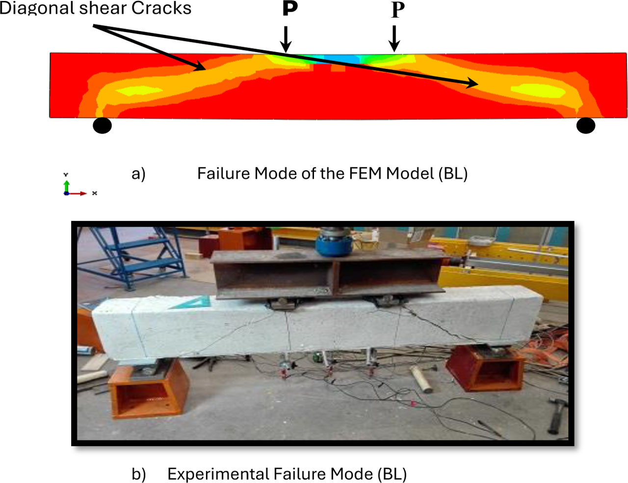
Figure 6:
Comparison of analysis with the expected failure mode of the control sample (BL) and FEM
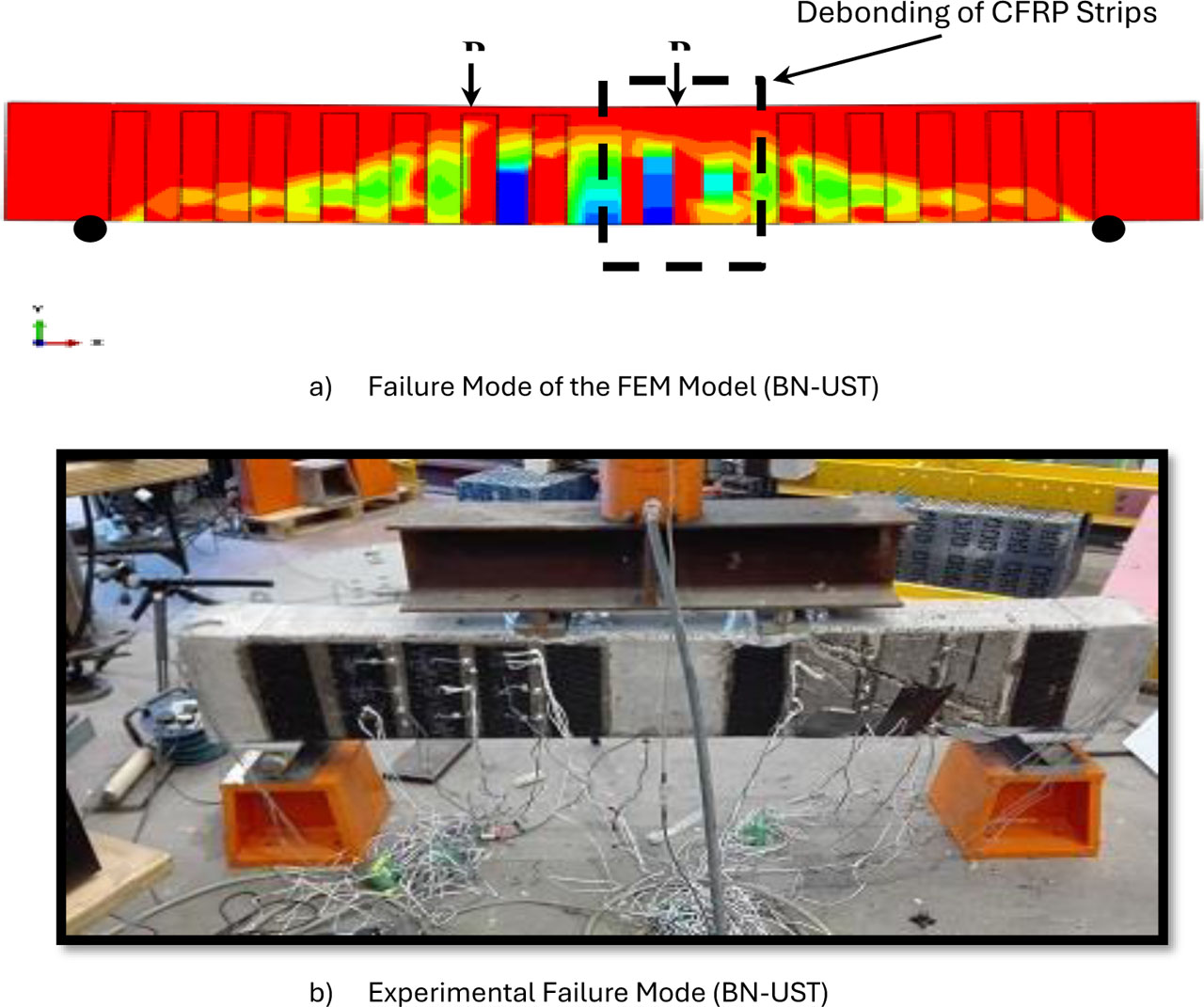
Figure 7:
Comparison of analysis with the expected failure mode of the control sample (BN-UST) and FEM
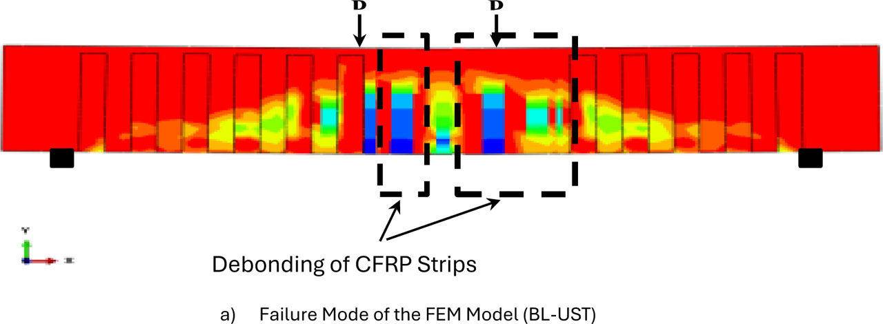
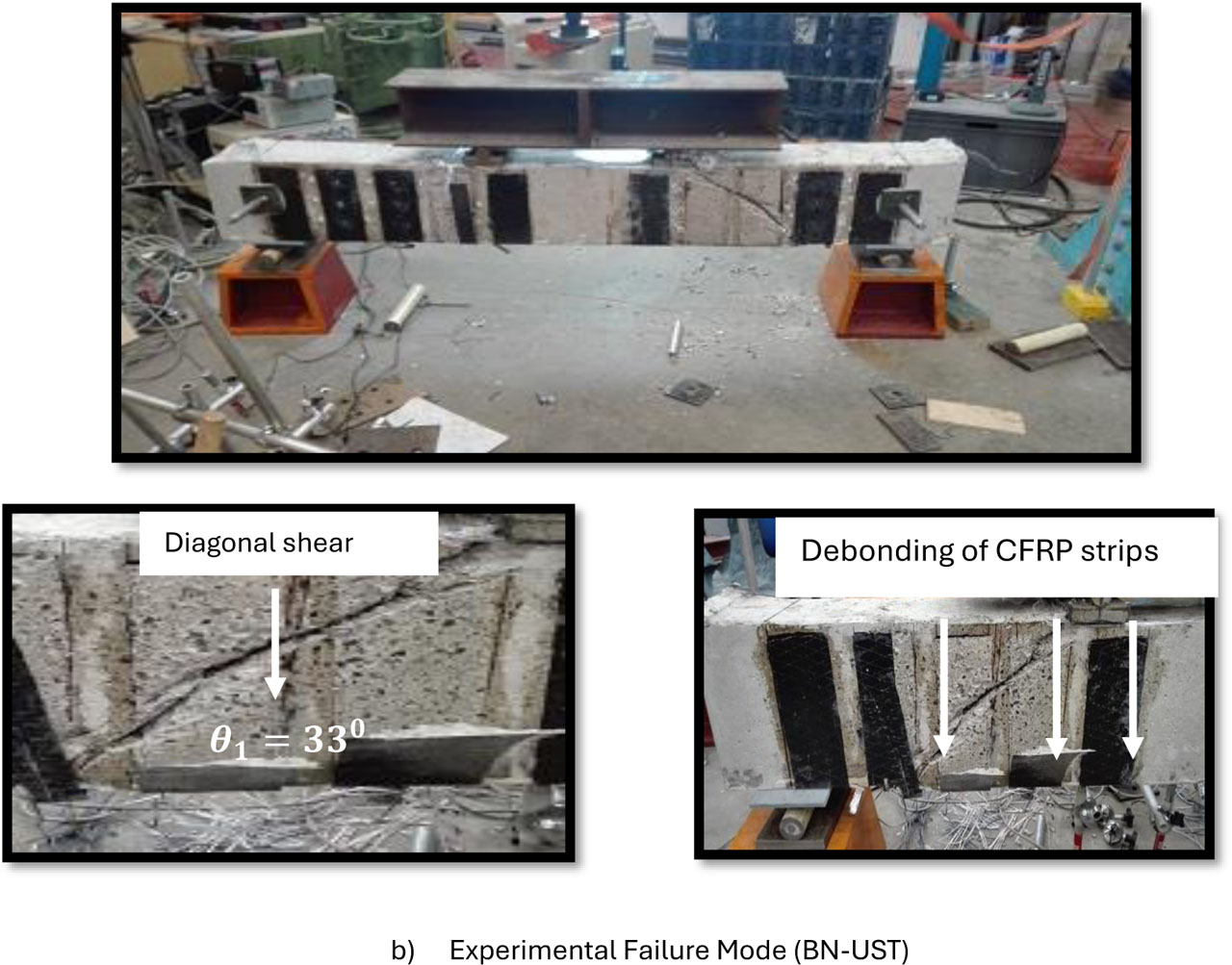
Figure 8:
Comparison of analysis with the expected failure mode of the control sample (BL-UST) and FEM
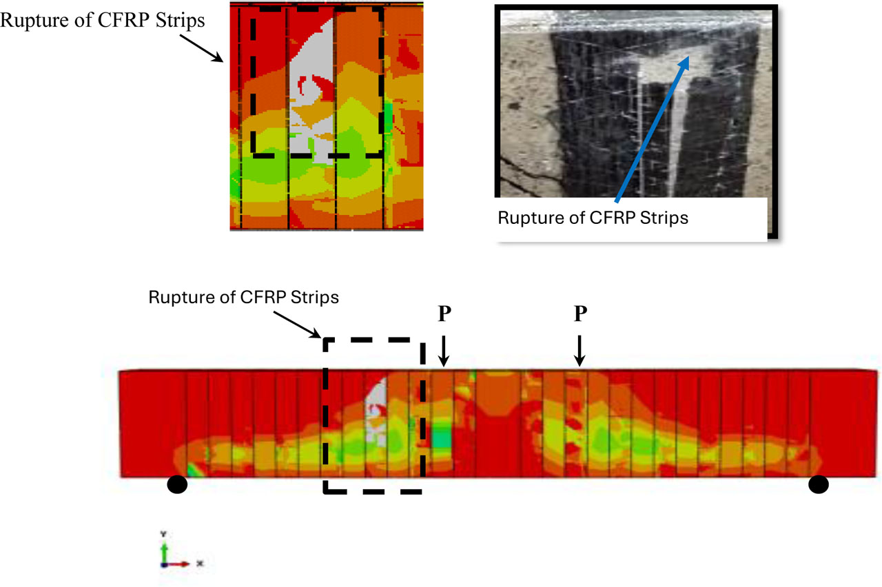
Figure 9:
Comparison of analysis with the expected failure mode of the control sample (BL-CST) and FEM
4. Parametric Study
A comprehensive parametric investigation was undertaken using the finite element software ABAQUS to evaluate the shear strengthening performance of NWC and LWC beams externally bonded with carbon fibre-reinforced polymer (CFRP) sheets. The primary objective was to quantify the influence of key design parameters on the structural response, failure mechanisms, and deformation behaviour of the strengthened beams.
Three principal variables were examined: concrete compressive strength (25, 40, and 55 MPa), CFRP elastic modulus (165, 240, and 640 GPa), and the number of CFRP layers (one, two, and three). Two beam configurations were modelled with each analysed under both U-shaped (UST) and closed-shaped (CST) CFRP arrangements to capture the interaction between external CFRP reinforcement and internal shear reinforcement. The numerical results were assessed in terms of ultimate load capacity, mid-span deflection, and failure mode, with particular emphasis on identifying the structural mechanisms governing the observed performance trends and elucidating the role of each parameter in determining the effectiveness of CFRP shear strengthening for both normal-weight and lightweight concrete beams. Tables 5 to 7 summarise the numerical results for ultimate load, midspan deflection, and failure modes with respect to concrete strength, CFRP elastic modulus, and number of CFRP layers.
Table 5:
Summary of Numerical Load Results
| Name of beam | Concrete Compressive Strength [MPa] | CFRP Elastic Modulus [GPa] | CFRP Layers Number | ||||||
|---|---|---|---|---|---|---|---|---|---|
| 25 | 40 | 55 | 165 | 240 | 640 | 1 | 2 | 3 | |
| BN-UST | 222.9 | 269.6 | 383.0 | 262.9 | 269 | 310.2 | 269.6 | 336.5 | 376.3 |
| BN-CST | 222.3 | 292.8 | 394.2 | 292.6 | 292.8 | 322.4 | 292.8 | 347.2 | 394.5 |
| BL-UST | 224.2 | 240.1 | 327.3 | 238.1 | 240.1 | 265.2 | 240.1 | 276.3 | 299.7 |
| BL-CST | 222.1 | 244 | 342.9 | 241.7 | 244 | 305.4 | 244.0 | 317.8 | 360.1 |
Table 6:
Summary of Numerical Deflection Results
| Name of beam | Concrete Compressive Strength [MPa] | CFRP Elastic Modulus [GPa] | CFRP Layers Number | ||||||
|---|---|---|---|---|---|---|---|---|---|
| 25 | 40 | 55 | 165 | 240 | 640 | 1 | 2 | 3 | |
| BN-UST | 6.9 | 7.98 | 10.3 | 12.9 | 7.98 | 7.4 | 7.98 | 7.7 | 7.1 |
| BN-CST | 8.1 | 9.75 | 11.5 | 8.7 | 9.75 | 13.2 | 9.75 | 10.2 | 10.5 |
| BL-UST | 6.8 | 7.7 | 9.6 | 12.1 | 7.7 | 7.1 | 7.7 | 7.5 | 6.8 |
| BL-CST | 8.4 | 11 | 13.1 | 9.7 | 11 | 14.3 | 11 | 11.6 | 12.8 |
Table 7:
Summary of failure mode Results
| Name of beam | Concrete Compressive Strength [MPa] | CFRP Elastic Modulus [GPa] | CFRP Layers Number | ||||||
|---|---|---|---|---|---|---|---|---|---|
| 25 | 40 | 55 | 165 | 240 | 640 | 1 | 2 | 3 | |
| BN-UST | DSF | DSF | RSF | RSF | DSF | DSF | DSF | DSF | DSF |
| BN-CST | RSF | RSF | RSF | RSF | RSF | RSF | RSF | RSF | DSF |
| BL-UST | DSF | DSF | DSF | DSF | DSF | DSF | DSF | DSF | DSF |
| BL-CST | DSF | RSF | RSF | RSF | RSF | RSF | RSF | RSF | DSF |
4.1. Effect of Concrete Compressive Strength
Concrete compressive strength was found to have a direct and substantial effect on the performance of CFRP-strengthened beams. Beams cast with higher-strength concrete consistently achieved higher ultimate loads due to both their improved intrinsic shear resistance and their superior compatibility with the externally bonded CFRP reinforcement. For example, in BN-UST specimens, increasing the concrete strength from 25 MPa to 55 MPa raised the ultimate capacity from 222.9 kN to 383.0 kN. This represents a significant enhancement in load-carrying capacity that cannot be attributed to CFRP alone, but to the interaction between substrate quality and external reinforcement.
The underlying mechanism lies in the improved aggregate interlock and greater fracture resistance of high-strength concrete. Stronger concretes provide better load transfer across developing cracks and enhance the bond capacity at the CFRP–concrete interface, thereby allowing the CFRP to mobilise more of its tensile strength before debonding occurs. Conversely, lightweight or low-strength concretes present weaker aggregate interlock and lower surface cohesion, making premature CFRP debonding more likely. In such cases, the strengthening effect of CFRP is limited not by the reinforcement itself, but by the inability of the substrate to sustain high interfacial stresses.
The influence of concrete strength was also evident in deflection behaviour. Beams with higher compressive strength generally exhibited reduced mid-span deflections at ultimate load, reflecting both their higher stiffness and their capacity to delay critical crack growth. For example, in BN-UST beams, deflection decreased from 6.9 mm at 25 MPa to 10.3 mm at 55 MPa, even though the latter beams carried substantially higher loads. This apparent increase in absolute deflection at higher strength is explained by the fact that while stiffness improved, the higher load capacity drove the beams further along the load–deflection curve before failure. Thus, higher concrete strength not only enhanced stiffness but also allowed beams to sustain greater loads and, consequently, somewhat larger deformations at ultimate failure.
Concrete strength also influenced the governing failure modes. In low-strength beams, shear failure due to CFRP debonding (DSF) was more prevalent, since the substrate could not sustain high bond stresses. By contrast, in beams with higher concrete strength, debonding was delayed, enabling the CFRP to be more effectively utilised until rupture (RSF) occurred. While rupture failures indicate better engagement of the CFRP reinforcement, they are more brittle in nature, underscoring the trade-off between strength and ductility in design.
From a practical standpoint, these findings highlight the importance of considering substrate quality in CFRP strengthening strategies. For low-strength concrete, designers should prioritise enhancing the bond surface through roughening, improved adhesive systems, or the use of mechanical anchorage to mitigate premature debonding and unlock the full potential of CFRP reinforcement. For high-strength concrete, by contrast, the design emphasis shifts toward controlling brittle rupture failure and ensuring adequate ductility. Figure 10 shows the influence of concrete strength on ultimate load and mid-span deflection.
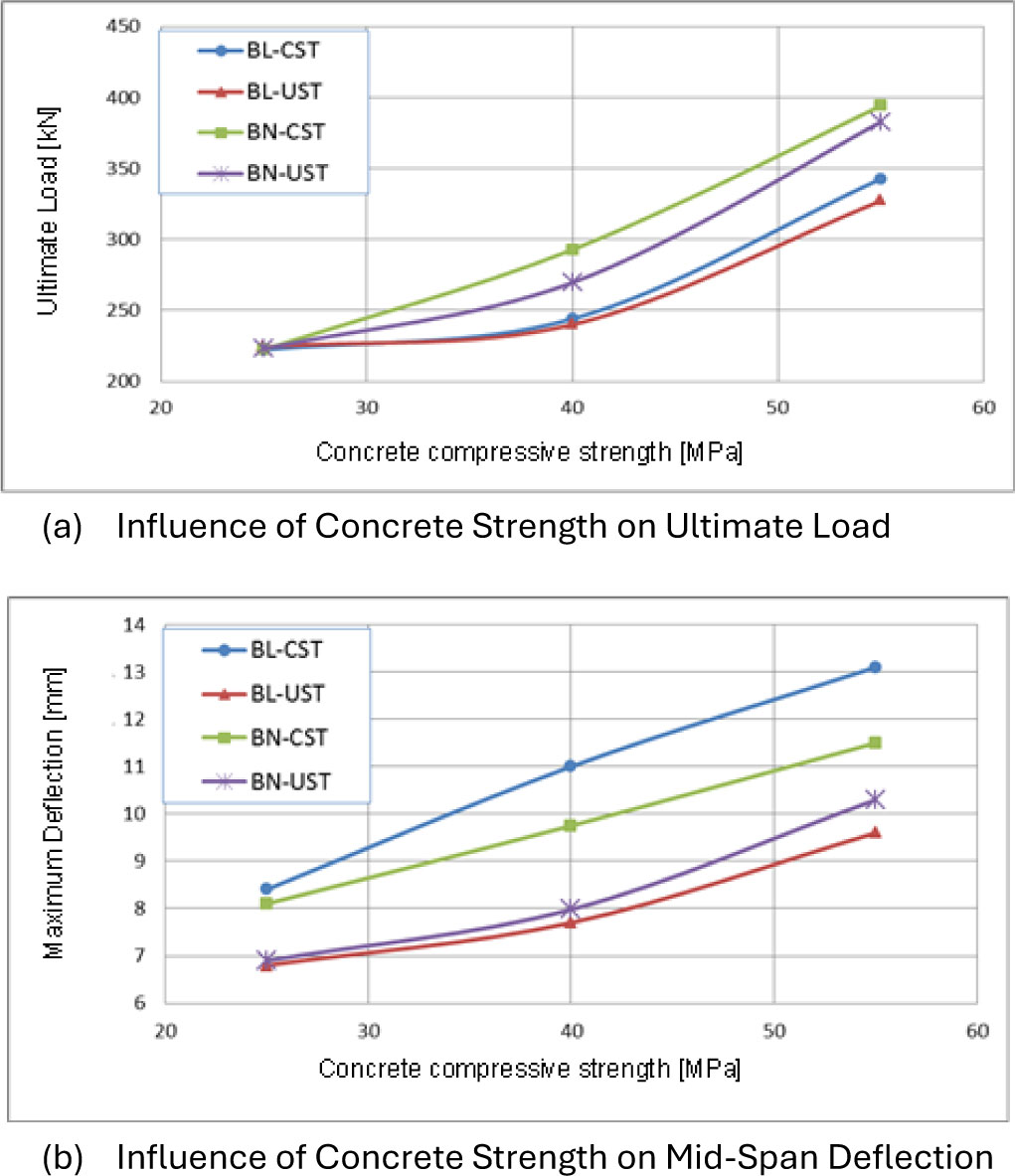
Figure 10:
Influence of the increase in strength of concrete on the ultimate load and mid-span deflection
4.2. Effect of CFRP Elastic Modulus
The elastic modulus of CFRP influenced the shear performance of the strengthened beams, although its impact was less dominant than the number of layers. Beams reinforced with higher-modulus CFRP exhibited greater ultimate capacities owing to the increased stiffness of the external reinforcement. For instance, in BN-CST beams, raising the modulus from 165 GPa to 640 GPa enhanced the capacity from 292.8 kN to 322.4 kN. A higher modulus reduces strain for a given applied stress, thereby restricting crack openings, delaying the formation of diagonal shear cracks, and promoting a more uniform stress distribution within the shear span.
The influence of CFRP modulus was most evident when only one layer was applied, since stiffness enhancement was the controlling factor in crack restriction. With multiple layers, however, the CFRP system already provided sufficient stiffness, and further increases in modulus yielded diminishing returns. In such cases, the governing failure mechanism shifted from deformation-driven debonding to strength-driven rupture or interfacial failure, meaning that the additional stiffness provided by a higher modulus became less beneficial.
The effect of modulus was also reflected in load–deflection behaviour. Generally, higher-modulus CFRP in reduced mid-span deflections at ultimate load by improving stiffness and crack control. For example, in BN-CST beams, deflection decreased from 13.2 mm with low-modulus CFRP (165 GPa) to 9.75 mm with a higher modulus (240 GPa). However, at high values of elastic modulus (640 GPa), the deflection again increased, not because the beam was less stiff, but because it carried a larger ultimate load before failure, leading to greater absolute deformation. This highlights the nonlinear relationship between stiffness and ultimate deflection: beams with high-modulus CFRP may deform more at failure despite being stiffer, since their load-carrying capacity is higher.
Failure modes were also sensitive to CFRP modulus. Beams with low-modulus CFRP often failed by debonding (DSF), as the higher strain demand led to excessive interfacial stresses and premature detachment of the laminate. As the modulus increased, CFRP strain demand decreased, reducing the likelihood of debonding and enabling the laminate to carry greater tensile forces. In beams with stirrups, this often shifted the failure mode to CFRP rupture (RSF). While rupture indicates more efficient utilisation of CFRP strength, it is also more brittle and sudden, raising concerns about ductility and safety in design.
From a practical perspective, these results suggest that high-modulus CFRP is most effective in thin applications (e.g., one layer), where stiffness is the limiting factor. In thicker CFRP systems, however, bond quality, anchorage, and surface preparation become more critical than modulus selection. Designers must therefore weigh the trade-off between strength and ductility: higher modulus improves stiffness and capacity but may shift failure behaviour toward brittle rupture, while lower modulus offers greater deformability but reduced strengthening efficiency. Figure 11 demonstrates the influence of CFRP elastic modulus increase on ultimate load and mid-span deflection.
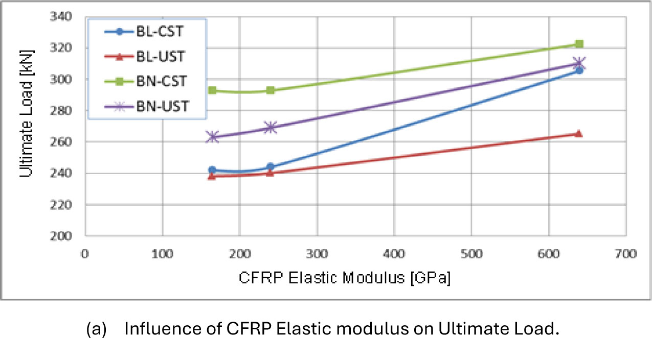
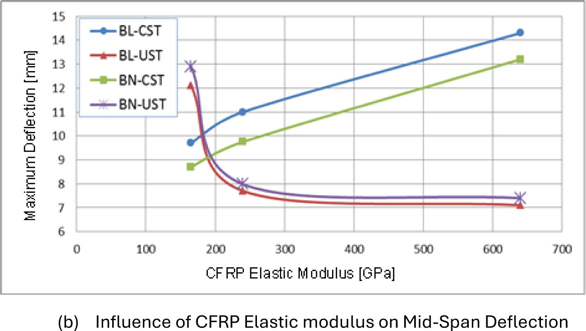
Figure 11:
Influence of increasing CFRP elastic modulus on ultimate load and mid-span deflection
4.3. Effect of Number of CFRP Layers
The number of CFRP layers was found to be the most influential parameter in improving the shear strength of the strengthened beams. Across all beam configurations, additional CFRP layers resulted in substantial improvements in ultimate load. For example, in BN-UST beams, increasing the CFRP from one to three layers raised the ultimate capacity from 269.6 kN to 376.3 kN, representing an enhancement of approximately 39%. Similarly, in BL-UST beams, capacity increased from 240.1 kN to 299.7 kN over the same range, demonstrating a significant strengthening effect.
The primary reason for this improvement lies in the increase in the effective CFRP cross-sectional area, which enables greater tensile force transfer across developing shear cracks. Multiple layers enhance crack-bridging action, delay the development and propagation of diagonal shear cracks, and improve confinement in shear-critical regions. Furthermore, the additional CFRP thickness distributes tensile stresses more evenly, reducing peak stress concentrations and allowing the strengthened beam to sustain higher loads before failure.
However, the rate of improvement tends to diminish beyond two layers a plateau effect because the bond between the concrete substrate and CFRP and becomes the limiting factor. Once interfacial stresses approach the adhesive capacity, further layers cannot be fully utilised, and premature debonding occurs before the CFRP achieves its ultimate tensile strength. This limitation is more pronounced in beams with lower strength of concrete, where the substrate’s surface cohesion is weaker and more prone to interfacial failure.
In terms of deflection behaviour, increasing the number of CFRP layers for U-shaped beams generally led to a reduction in midspan deflection at ultimate load, indicating an overall increase in stiffness. The added CFRP reinforcement restricted crack growth and improved the beam’s ability to resist deformation under load. Nevertheless, this trend was not strictly proportional; in cases of Closed-shaped specimens, beams with more layers exhibited slightly higher deflections at failure. This is explained by the fact that additional layers allowed the beam to carry higher ultimate loads, meaning that even with increased stiffness, the absolute deflection at peak load could be greater.
Regarding failure modes, U-shaped beams with fewer CFRP layers were more likely to fail by shear-induced CFRP debonding because the available bonded area and thickness were insufficient to sustain high interfacial stresses. As the number of layers increased, particularly in Closed-shaped configurations, the failure mode often shifted towards CFRP rupture. This occurred because the thicker CFRP laminates could carry higher tensile forces, and the presence of stirrups reduced crack widths, delaying debonding and allowing the CFRP to reach its tensile capacity. While rupture failures indicate better utilisation of the CFRP material, they are also more brittle in nature, requiring careful consideration of ductility and safety in design.
From a design perspective, increasing the number of CFRP layers is an effective and straightforward method for improving shear capacity, stiffness, and crack control. However, its effectiveness is ultimately constrained by bond performance, and excessive layering may lead to brittle rupture modes. Therefore, beyond an optimal layer count, further performance gains should focus on improving bond strength through enhanced surface preparation, better adhesive selection, mechanical anchorage, or hybrid reinforcement strategies rather than simply adding CFRP thickness. Figure 12 shows the influence of the number of CFRP layers on ultimate load and midspan deflection.
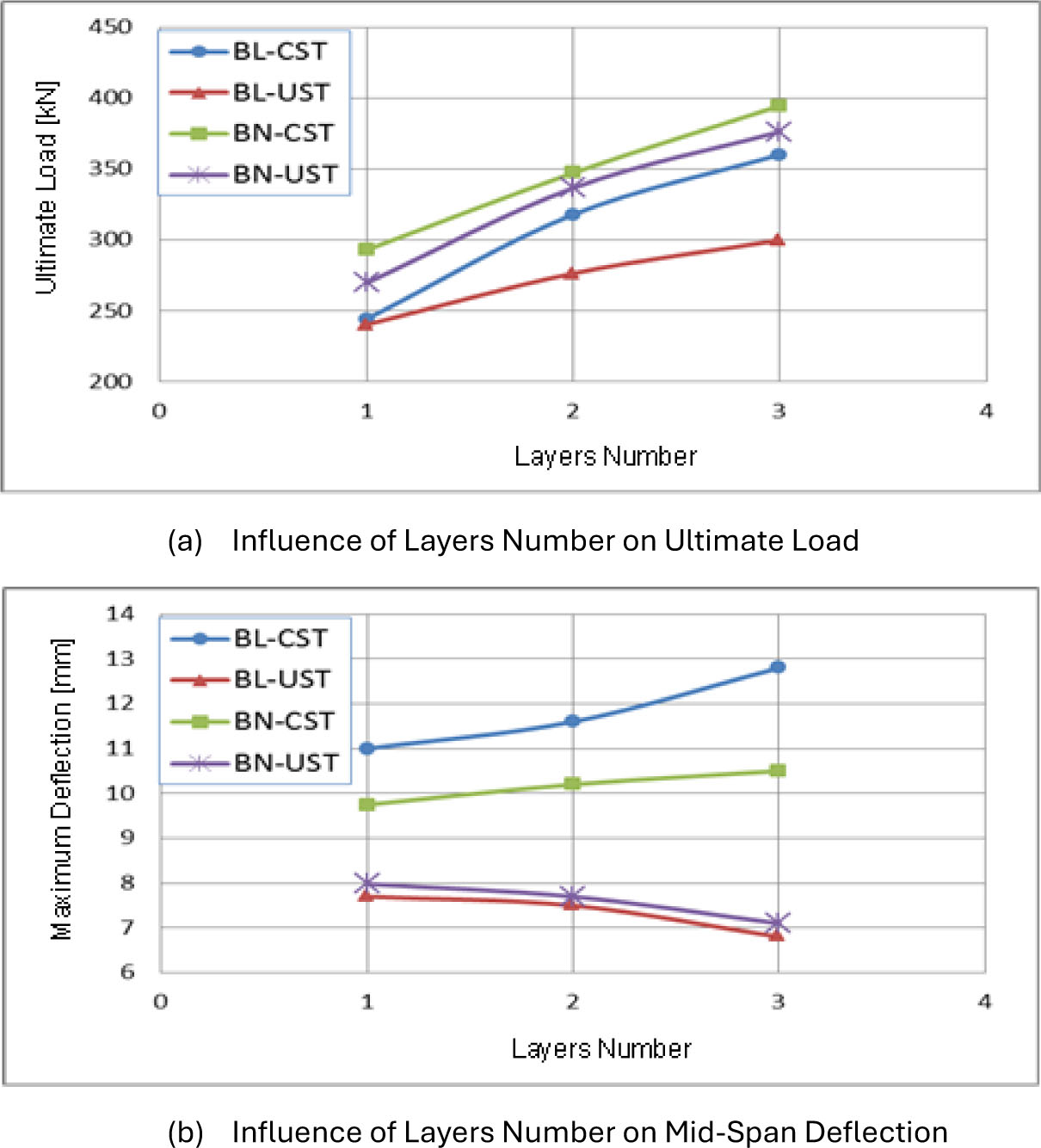
Figure 12:
Influence of increasing the number of CFRP layers on ultimate load and midspan deflection
5. Conclusion
This study conducted an in-depth numerical analysis of the shear behaviour of LWC beams reinforced with CFRP. An ABAQUS finite element (FE) model was developed and calibrated against the experimental study of Al-Allaf (2019). The model was highly accurate in predicting load-deflection response, ultimate capacity, crack development, and failure modes. Based on the findings, it is possible to point out several important observations:
The numerical model was able to capture the overall structural behaviour as well as localised failure modes including CFRP debonding and rupture. Its predictions were closely matched with experimental results with ultimate load differences of less than 9%. This validates the strength of the modelling method and its usefulness as a credible research and design tool.
The shear capacity increased with the increase in compressive strength of LWC beams. stronger concrete enhanced the aggregate interlock and bond performance, which postponed CFRP debonding and enabled the reinforcement to transfer more load. This shows the significance of the quality of the substrate, since beams with stronger concrete offer a better foundation to successful CFRP strengthening.
Behaviour of concrete beams was greatly influenced by the modulus of elasticity of CFRP. The stiffness was enhanced and crack growth was restricted by high-modulus CFRP, leading to increased ultimate strength. Nevertheless, excessive rigid reinforcement enhanced the possibility of brittle failure, which demonstrated that the selection of CFRP should be based on a balance between strength and ductility to prevent catastrophic failure.
The most important factor affecting shear performance was the number of CFRP layers. The layers increased shear strength and stiffness through better crack-bridging action and stress distribution. Nevertheless, the addition of more layers may result in bond constraints between the CFRP and the concrete, thus decreasing performance and frequently resulting in early debonding or failure. Thus, safe and efficient design requires an optimal balance between the number of layers and bond capacity.
Acknowledgements
The authors wish to convey their profound appreciation to [Prof. Dr. Abdulkader Ismail Al-Hadithi] for his invaluable mentorship and insightful critiques.
Notes
[2] Contributed by Author Contributions
K.R. conceptualized and structured the research study. M.E. executed the theoretical modeling and gathered the necessary data. Data interpretation and manuscript composition saw a crucial influence from M.R.M.Al-A. efforts. All writers engaged in a comprehensive review and gave their thumbs up for the final copy of the manuscript, thereby consenting to assume accountabilities for all areas of the research effort.