

1. Introduction
Welded steel structures subjected to cyclic variable loading are prone to fatigue damage. Fatigue damage represents the initiation and subsequent propagation of fatigue cracks through the structural material, typically in the weld zone and the heat-affected zone (HAZ). The primary causes are material and geometric imperfections introduced during welding, which act as stress concentrators and accelerate the initiation and growth of these cracks (Hobbacher, 2008). As the strength of a material increases, its ductility typically decreases. When using and welding high-strength steels (HSS), it is essential to select appropriate welding materials and procedures to prevent a significant reduction in ductility in the weld joint area, which would adversely affect the overall fatigue performance of the welded joint. To maintain suitable fatigue properties, it is crucial to choose an appropriate combination of welding parameters, heat input, preheating or annealing (Hobbacher & Baumgartner, 2024).
The methods collectively referred to post-welding treatments for improving fatigue properties include several options for weld toe modification depending on the selected technology. The basic technologies are commonly used surface burr grinding (BG) (Pedersen et al., 2010) or TIG dressing (Huo, 2004). Other methods involve mechanical surface strengthening, collectively referred to High-Frequency Mechanical Impact (HFMI). The most frequently applied modifications are ultrasonic impact treatment (UIT) (Marquis & Barsoum, 2013; Gunther et al., 2005; Cheng, 2003), ultrasonic peening (UP) (Kudryavtsev et al., 2007), high-frequency impact treatment (HiFIT) (Marquis & Barsoum, 2013; Krasnowski, 2018; Telljohann & Dannemeyer, 2009) or pneumatic impact treatment (PIT) (Gerster et al., 2013).
HFMI treatment is based on mechanical surface hardening of the weld toe region, achieved through localized plastic deformation and the introduction of compressive residual stresses. The plastic deformation is induced by impacting the surface with a steel pin at a frequency of approximately 100 Hz. This process creates a smooth radius at the weld toe, improving the notch geometry. As a result of the deformation, compressive stresses are introduced into the surface layer of the weld, which help to reduce undesirable tensile stresses (e.g. residual stresses from welding or other thermal manufacturing processes), thereby enhancing the fatigue life of the treated welded joints. The steel pin is mounted in a tool holder, which is guided along the weld toe either manually or semi-automatically. The compressive stresses introduced by the HFMI treatment typically penetrate to a depth of 1–2 mm below the surface, depending on the selected material thickness. The distribution of the induced compressive stress is nonlinear and the effect diminishes with increasing distance from the surface (Marquis & Barsoum, 2013; Al-Karawi et al., 2021; Marquis & Barsoum, 2016; Krasnowski, 2018; Telljohann & Dannemeyer, 2009).
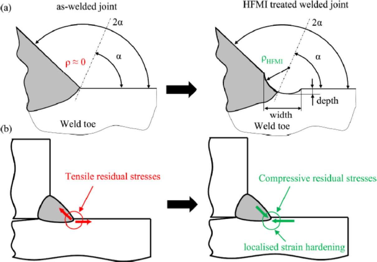
Figure 1:
Principle of the HFMI treatment method (Campagnolo et al., 2021)
However, when applying the HFMI method, certain differences in fatigue behavior arise compared to conventional welded joints and assessments based on Eurocode. These differences are primarily due to the principle of mechanical surface hardening. The decisive factor is no longer solely the absolute stress range, but also the mean stress (i.e., the difference between maximum and minimum stress), expressed by the load ratio parameter R. As the R ratio increases, the effectiveness of the HFMI treatment (and consequently the fatigue life) decreases (Marquis & Barsoum, 2016; Leitner & Barsoum, 2020). This is because higher mean tensile stresses lead to a faster relaxation of the compressive stresses introduced into the surface layer, resulting in a more rapid loss of the HFMI effect. Material strength also plays a significant role. According to current experimental results, the fatigue life of welded joints treated with HFMI increases proportionally with the yield strength of the base material. This may be explained by the differing microstructures of high-strength steels, where a higher proportion of martensite and bainite is typically present structures, which may causes capable of absorbing greater compressive residual stresses induced by the HFMI treatment. The resulting improvement in fatigue life is generally reflected by an increased detail category, depending on the steel strength class and the level of mean stress (Yıldırım et al., 2015; Marquis et al., 2025).
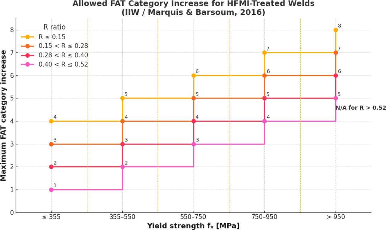
Figure 2:
Allowed FAT category increase for HFMI treated Welds (Marquis & Barsoum, 2016)
This study therefore focused on various steel grades (ranging from S355 to S960) and different loading parameters. The subject of the investigation was the fabrication of welded structural details (V and X butt welds) representing realistic bridge components containing fatigue cracks. The objective of the study was to simulate the repair of such structures and to evaluate the potential benefits of the HFMI method under subsequent identical cyclic loading. This process represents a realistic simulation of the repair of a fatigue-damaged structure and explores the possible application of the HFMI method for these scenarios.
2. Experimental programme
2.1. Materials and test specimens
In this study, basic specimens with V and X full penetration butt welds were designed to represent typical transverse weld details found, for example in bridge structures. Test specimens with dimensions of 300×80×20 mm were manufactured and subjected to four-point bending in the laboratory. Four steel grades were selected: S355J2+N, S460NL, S690QL and S960QL. This selection made it possible to obtain results across different strength classes and to compare them with the recommendations provided by the IIW.
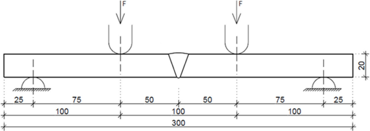
Figure 3:
Geometry of the specimen with butt V-weld (identical for the specimen with X-weld)
A total of 52 test specimens were manufactured for fatigue testing (26x butt V-weld and 26x butt X-weld). The following table shows their distribution by weld treatment.
2.2. Manufacturing of specimens and technical parameters
The manufacturing of the specimens was made in the university’s welding workshop. First, individual Welding Procedure Specifications (WPS) were developed to ensure uniformity and repeatability of the welding process. The specimens were then welded under identical conditions. The following table lists the specific technical parameters used during the welding of the specimens.
Table 2:
Technical manufacturing parameters
| S355 specimens: Technical manufacturing parameters | |
| Welding method | 135 (MAG) according to EN ISO 4063 |
| Filler material | EN ISO 14341-A: G46 3 C1 4Si1/G50 5 M21 4Si1 |
| Shielding gas | M21 (82% Ar + 18% CO2) – STARGON 18 |
| Preheat temperature | - |
| S460 specimens: Technical manufacturing parameters | |
| Welding method | 135 (MAG) according to EN ISO 4063 |
| Filler material | EN ISO 14341-A: G46 3 C1 4Si1/G50 5 M21 4Si1 |
| Shielding gas | M21 (82% Ar + 18% CO2) – STARGON 18 |
| Preheat temperature | - |
| S690 specimens: Technical manufacturing parameters | |
| Welding method | 135 (MAG) according to EN ISO 4063 |
| Filler material | EN ISO 16834-A: G 69 4 M21 Mn3Ni1CrMo |
| Shielding gas | M21 (82% Ar + 18% CO2) – STARGON 18 |
| Preheat temperature | 100 °C |
| S960 specimens: Technical manufacturing parameters | |
| Welding method | 135 (MAG) according to EN ISO 4063 |
| Filler material | EN ISO 16834-A: G 89 4 M20 Mn4Ni2CrMo |
| Shielding gas | M21 (82% Ar + 18% CO2) – STARGON 18 |
| Preheat temperature | 150 °C |
After the manufacturing was completed, non-destructive testing (NDT) of the welds was made. First, a visual inspection (VT) was performed, followed by magnetic particle testing (MT) and ultrasonic testing (UT). The visual inspection was evaluated according to EN ISO 5817 (quality level B), which corresponds to the standard typically applied in bridge construction and is suitable for welded details subjected to fatigue loading.
The specimens were divided into two main groups after the completion of NDT inspections. The first group consisted of as-welded samples, which were left in their original welded condition without any further treatment. The second group comprised samples treated with the HFMI treatment. It was applicated manually with using the Hifit device at a frequency of approximately 100 Hz with a pin diameter of 3 mm. Subsequently, the samples were transported to the testing laboratory for the commencement of fatigue tests.
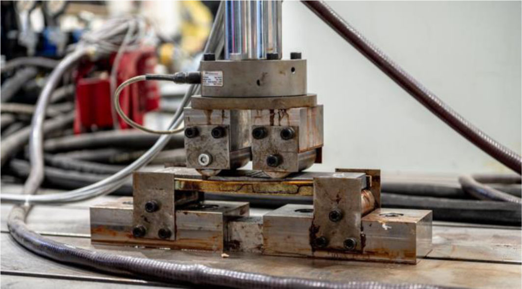
Figure 4:
Testing equipment with specimen during the fatigue experiment
2.3. Experimental procedure
Fatigue testing of the as-welded samples was initiated first. The theoretical stress range was calculated according to Eurocode 3 (EN 1993-1-9), and a basic stress ratio of R = 0.1 was established. The samples were tested at several variable stress amplitude levels in order to determine the resulting S-N curves. The specimens were equipped with strain gauges to monitor and record the normal stress over time. The criterion for terminating the fatigue test was reaching the limit number of cycles without failure (runout) or the initiation of a fatigue crack, which was typically indicated by a drop in the strain gauge readings and subsequently confirmed by NDT penetrant testing (PT). The criterion for reaching the limit number of cycles without failure (runout) was set at 5 million cycles (in some first cases 10 million cycles). After finishing the fatigue tests of the as-welded specimens, the specimens treated with the HFMI method were tested. They were loaded with the same stress range parameters and stress ratio as the as-welded samples. In cases where no failure occurred during the fatigue test (runout), the normal stress values were increased according to calculations to obtain conclusive fatigue results.
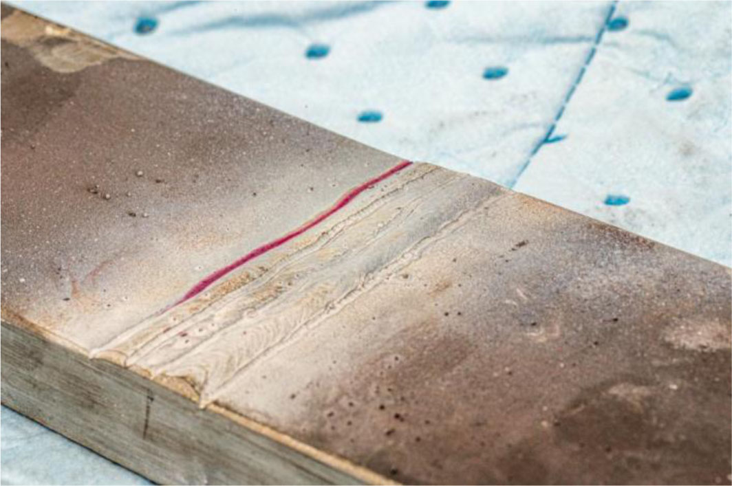
Figure 5:
Localization of the fatigue crack using NDT penetrant testing (PT) after completion of loading
Finally, selected as-welded samples containing fatigue cracks were subjected to a repair procedure. This involved grinding out the entire area of the fatigue crack, followed by re-welding using the same parameters as during the original sample fabrication. This process simulates a realistic repair procedure applicable to actual welded structures. After the repair welding, the HFMI treatment was applied to all repaired specimens using the same parameters as those used for HFMI treatment on new welded joints.
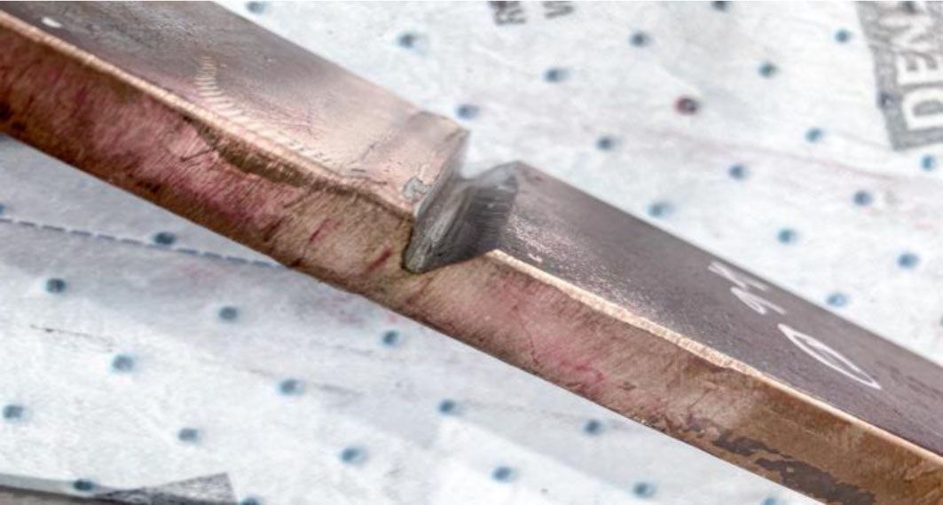
Figure 6:
Repair of a specimen affected by a fatigue crack
3. Results
The results of the fatigue tests are categorized according to the steel grades. Recommended S-N curves are evaluated for the as-welded samples, along with the potential theoretical upgrade of the detail category when applying HFMI, in accordance with IIW Recommendations (Marquis & Barsoum, 2016).
The evaluation begins with S355 specimens tested under a stress ratio of R = 0.1. Based on the obtained results, the samples treated with HFMI clearly demonstrate an improvement in fatigue life by four detail categories (or more), in accordance with the IIW Recommendations (Marquis & Barsoum, 2016). Even the specimens without any post-weld treatment (as welded) exhibit higher fatigue life than predicted, which can be attributed to the conservative nature of the EN 1993-1-9 standard. Particularly promising are the results of the repaired welds treated with HFMI, which show fatigue performance comparable to newly welded joints with HFMI treatment. This finding indicates significant potential for the future application of HFMI technology to repair welded structures made usually of S355 grade steels (e.g. bridges).
The following table presents the results of the number of cycles to failure, along with their graphical representation using the corresponding S-N curves. For the evaluation of the results, standard S–N curves according to the currently valid EN 1993-1-9 (for as-welded specimens) and the IIW Recommendations (for HFMI specimens) are used (Marquis & Barsoum, 2016).
Table 3:
Number of cycles to failure for S355 steel grade specimens
| Material | S355 | ||
|---|---|---|---|
| Stress ratio R | 0.1 | ||
| Spec. number | Treatment | Stress range [MPa] | Number of cycles to failure |
| 1 | As Welded | 100 | 10 000 000* |
| 2 | As Welded | 100 | 10 000 000* |
| 3 | As Welded | 200 | 1 531 011 |
| 4 | As Welded | 200 | 1 486 900 |
| 5 | HFMI | 200 | 10 000 000* |
| 6 | HFMI | 200 | 5 000 000* |
| 7 | HFMI | 250 | 5 000 000* |
| 8 | HFMI | 300 | 1 900 389 |
| 9 | HFMI repair | 300 | 2 728 703 |
| 10 | HFMI repair | 300 | 1 741 976 |
| 11 | HFMI repair | 320 | 474 210 |
| 12 | HFMI repair | 320 | 974 818 |
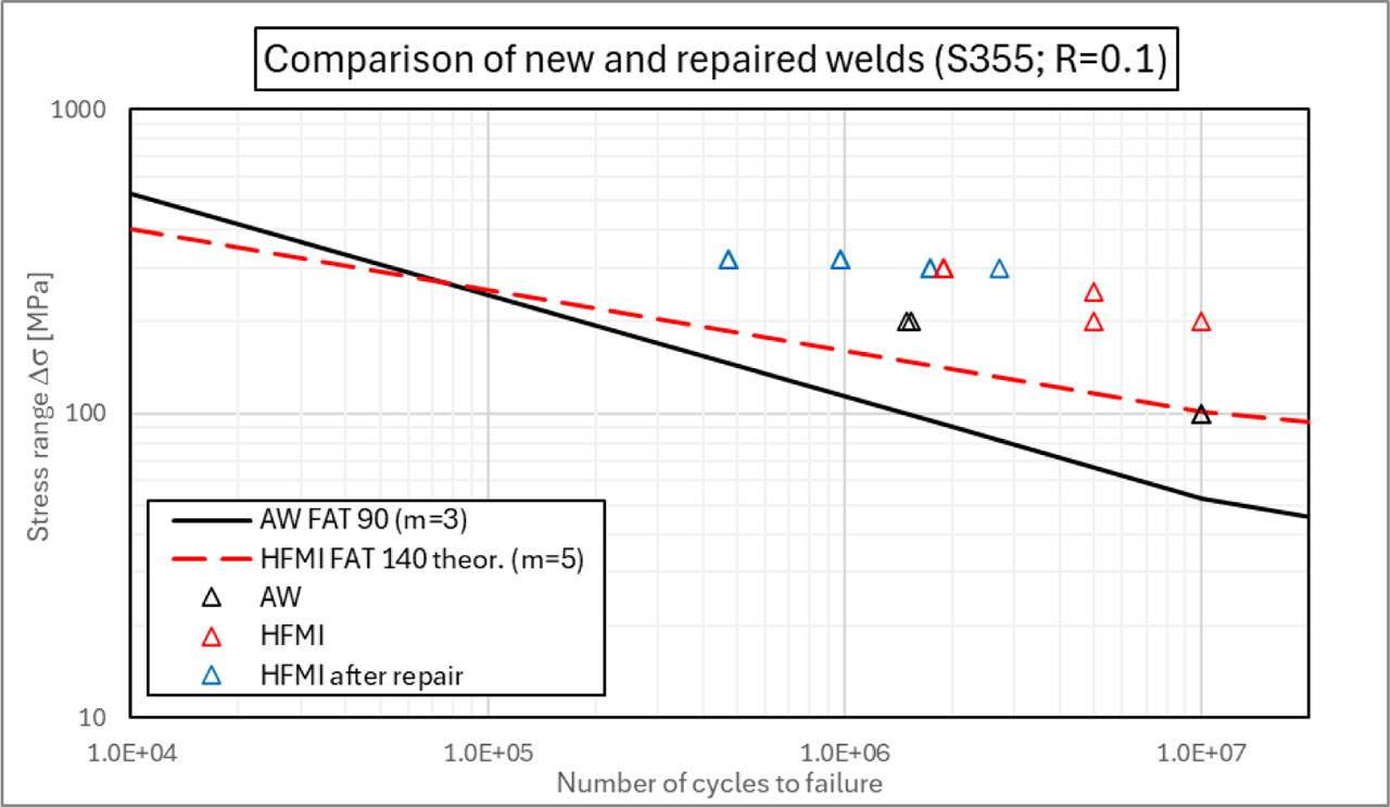
Figure 7:
Comparison of results S355 steel grade specimens
Subsequently, the evaluation was made for S460 specimens tested under a stress ratio of R = 0.1. According to the obtained results, the HFMI-treated specimens again clearly demonstrate an increase in fatigue life by five detail categories (or more), which is in line with the IIW Recommendations (Marquis & Barsoum, 2016). Once again, the as-welded specimens also show improved fatigue life, which can be attributed to the conservative nature of the EN 1993-1-9 standard and the high quality of the welding process combined with thorough NDT inspections. The results of the repaired welds treated with HFMI once again show significant potential, achieving fatigue performance comparable to newly welded joints with HFMI treatment.
Table 4:
Number of cycles to failure for S460 steel grade specimens
| Material | S460 | ||
|---|---|---|---|
| Stress ratio R | 0.1 | ||
| Spec. number | Treatment | Stress range [MPa] | Number of cycles to failure |
| 13 | As Welded | 200 | 474 157 |
| 14 | As Welded | 200 | 3 018 047 |
| 15 | As Welded | 300 | 210 929 |
| 16 | As Welded | 300 | 331 088 |
| 17 | As Welded | 350 | 129 096 |
| 18 | As Welded | 350 | 309 218 |
| 19 | HFMI | 200 | 4 393 464 |
| 20 | HFMI | 200 | 5 000 000* |
| 21 | HFMI | 300 | 984 402 |
| 22 | HFMI | 350 | 847 345 |
| 23 | HFMI | 350 | 947 066 |
| 24 | HFMI repair | 300 | 589 985 |
| 25 | HFMI repair | 300 | 1 175 960 |
| 26 | HFMI repair | 350 | 254 244 |
| 27 | HFMI repair | 350 | 688 634 |
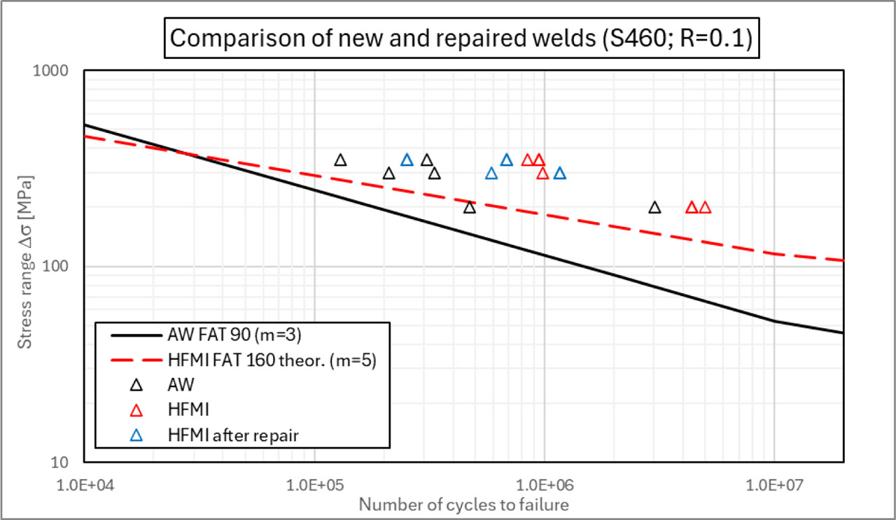
Figure 8:
Comparison of results S460 steel grade specimens
Furthermore, an evaluation was performed for S690 specimens tested under a stress ratio of R = 0.1. According to the obtained results, the HFMI-treated specimens once again clearly exhibit an increase in fatigue life by six detail categories (or more), which is consistent with the IIW Recommendations (Marquis & Barsoum, 2016). The as-welded specimens also demonstrate improved fatigue life. As in the previous cases, the repaired welds treated with HFMI achieved fatigue performance comparable to newly welded joints with HFMI treatment.
Table 5:
Number of cycles to failure for S690 steel grade specimens
| Material | S690 | ||
|---|---|---|---|
| Stress ratio R | 0.1 | ||
| Spec. number | Treatment | Stress range [MPa] | Number of cycles to failure |
| 28 | As Welded | 200 | 2 674 867 |
| 29 | As Welded | 300 | 501 424 |
| 30 | As Welded | 300 | 372 388 |
| 31 | As Welded | 500 | 55 796 |
| 32 | As Welded | 500 | 79 230 |
| 33 | HFMI | 300 | 5 000 000* |
| 34 | HFMI | 350 | 5 000 000* |
| 35 | HFMI | 500 | 167 150 |
| 36 | HFMI | 500 | 289 026 |
| 37 | HFMI repair | 400 | 426 198 |
| 38 | HFMI repair | 400 | 116 523 |
| 39 | HFMI repair | 450 | 309 494 |
| 40 | HFMI repair | 450 | 160 857 |
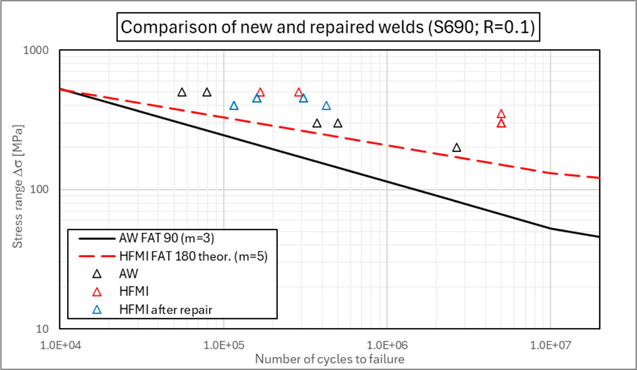
Figure 9:
Comparison of results S690 steel grade specimens
Finally, the evaluation was carried out for S960 steel specimens. According to the obtained results, the HFMI treatment generally extended the fatigue life of the welded joints; however, the S-N curves are very similar to those of the as-welded specimens. This can be attributed to the specific fatigue behavior of high-strength steels (HSS) and the influence of welding on this type of material. Another contributing factor may be the testing under high stress levels, which led to early failure of the specimens. In this case, a more detailed evaluation would require conducting additional series of long-duration fatigue tests with lower stress ranges, better representing long-term fatigue behavior.
Table 6:
Number of cycles to failure for S960 steel grade specimens
| Material | S960 | ||
|---|---|---|---|
| Stress ratio R | 0.1 | ||
| Spec. number | Treatment | Stress range [MPa] | Number of cycles to failure |
| 41 | As Welded | 300 | 492 569 |
| 42 | As Welded | 500 | 55 205 |
| 43 | As Welded | 500 | 60 774 |
| 44 | As Welded | 800 | 16 832 |
| 45 | HFMI | 300 | 5 000 000* |
| 46 | HFMI | 500 | 70 656 |
| 47 | HFMI | 500 | 293 794 |
| 48 | HFMI | 800 | 15 584 |
| 49 | HFMI repair | 450 | 110 727 |
| 50 | HFMI repair | 450 | 172 590 |
| 51 | HFMI repair | 500 | 32 423 |
| 52 | HFMI repair | 500 | 110 359 |
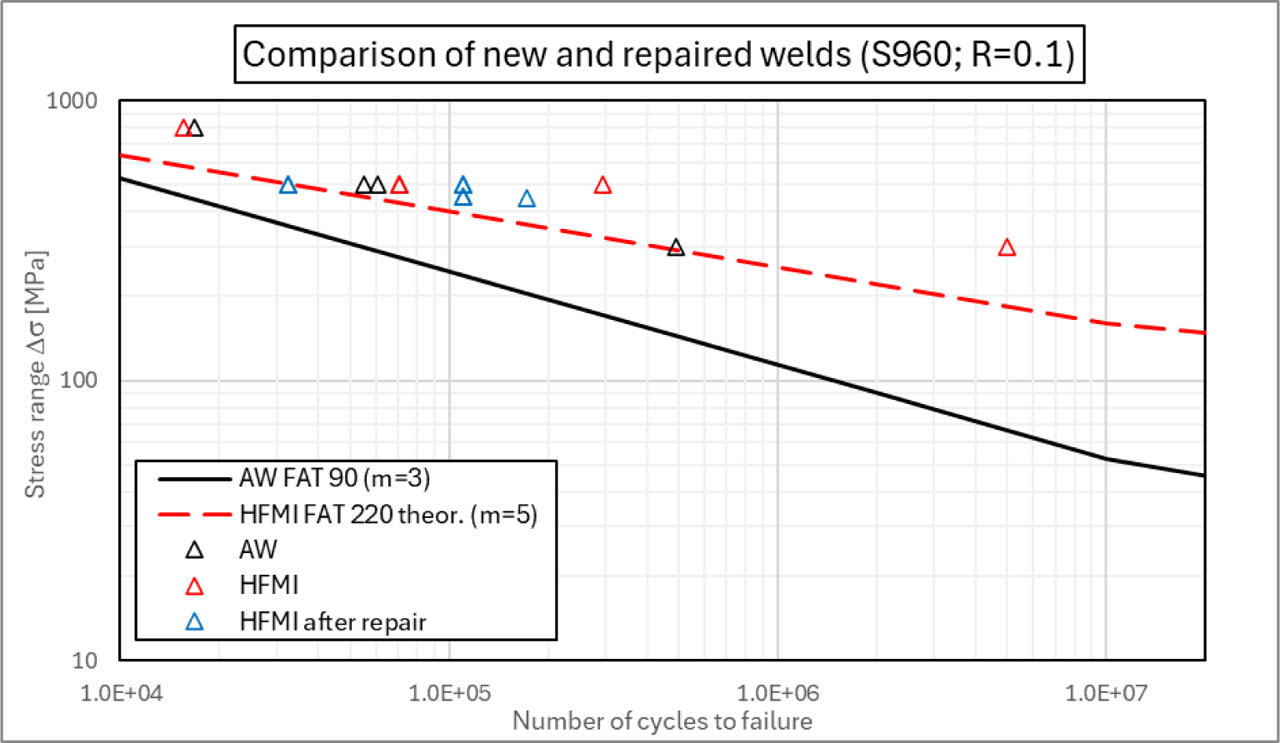
Figure 10:
Comparison of results S960 steel grade specimens
4. Conclusion
This study comprehensively evaluated the effectiveness of the High Frequency Mechanical Impact (HFMI) treatment in improving the fatigue life of welded steel joints across a range of steel grades, from standard structural steel (S355) to high-strength steels (S960). The experimental results demonstrate an increase in fatigue strength with increasing yield strength of the base material, which is consistent with the findings reported in studies (Leitner & Barsoum, 2020; Yildirim & Marquis, 2012; Pijpers et al., 2009).
Through a series of controlled four-point bending fatigue tests, the performance of HFMI-treated specimens was compared to untreated (as welded) specimens and subsequently to repaired welds subjected again to HFMI treatment. The four-point bending test results confirmed the assumptions in accordance with the IIW recommendations (Marquis & Barsoum, 2016), despite the fact that the majority of experiments reported in the literature have been evaluated under axial loading. Nevertheless, a comparison of results indicates good agreement between axial and bending loading in many cases, as demonstrated, for instance, by study (Shams-Hakimi et al., 2017).
The experimental results consistently demonstrated a significant increase in fatigue life for specimens treated with HFMI. For S355 steel an improvement of at least four detail categories was observed, for S460 five categories and for S690 up to six categories, all in alignment with the IIW Recommendations (Marquis & Barsoum, 2016). The increase in fatigue life across different steel strength grades is likewise reported by studies focusing on yield strength and the effect of HFMI (Leitner & Barsoum, 2020; Yildirim & Marquis, 2012; Pijpers et al., 2009). Even the as welded specimens showed longer fatigue life than the default classifications provided in EN 1993-1-9, which can be attributed to the standard’s conservative assumptions and the high-quality execution of welding and NDT procedures in this study.
Repaired specimens – those in which fatigue cracks were removed and the welds re-executed using identical parameters, followed by HFMI treatment – proved particularly promising. Their fatigue performance closely matched that of new HFMI treated welds. This finding suggests a high potential for the application of HFMI not only as a preventive post-weld treatment but also as an effective method for the rehabilitation of fatigue-damaged steel structures. This could prove especially beneficial in the maintenance and life extension of steel bridges made of standard structural steels such as S355. This observation, as well as the appropriateness of HFMI application, is also discussed in other studies (Ummenhofer et al., 2013; Yıldırım, 2016).
In the case of ultra-high-strength steel S960, the HFMI treatment did result in a moderate increase in fatigue life, however the S-N curves of the treated and untreated specimens were very similar. This may be explained by the distinct fatigue behavior of HSS, where the welding process and the associated thermal effects can reduce the benefit gained from mechanical surface treatments like HFMI. Additionally, the testing at high stress levels may have caused early failure, masking the potential benefits of the treatment. For a more complete evaluation of HFMI effect on S960, further testing under lower stress amplitudes and longer fatigue durations is recommended.
In summary, the HFMI method has been shown to significantly enhance fatigue resistance in welded steel joints, particularly in steels up to S690. Its effectiveness for both new and repaired welds makes it a strong candidate for broader application in fatigue-critical steel structures. Future research can focus on optimizing its use for ultra-high-strength steels and on integrating HFMI more broadly into fatigue design and maintenance strategies for critical infrastructure.
Acknowledgements
This research was supported by the Technology Agency of the Czech Republic under project No. CL02000098, “Carbon footprint reduction in transport infrastructure by optimized design and HFMI treatment for high strength and corrosion-resistant steel.”