

Table 1:
Concrete mixes
| Mixes all in [kg/m3] | Fine sand | cement | Water | Superplastizer | Silica Fume | Fly Ash | Compressive strength [MPa] 28 days |
| 1070 | 970 | 184 | 33.4 | 107 | 192.6 | 126.97 |
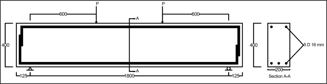
Figure 1:
Dimension and reinforcement details of specimens (all dimensions in mm)
Table 2:
CFRP-Reinforcement Configurations and Strengthening
| Sample | CFRP strengthening type at each side | Cfrp orientation [degrees] |
|---|---|---|
| RC-C | Without | / |
| RC-U-90-100 | U- shape,100 mm width,150mm spacing c/c | 90° |
| RC-U-45-100 | U- shape,100 mm width,150mm spacing c/c | 45° |
| RC-2side-90-600 | 2-sided-shape,600 mm width | 90° |
| RC-U-90-600 | U- shape,600 mm width | 90° |
| RC-Full-Face | Full Face | 90° |
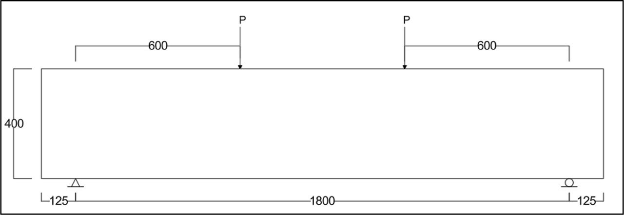
Figure 2:
(RC-C) control specimen (all dimensions in mm)
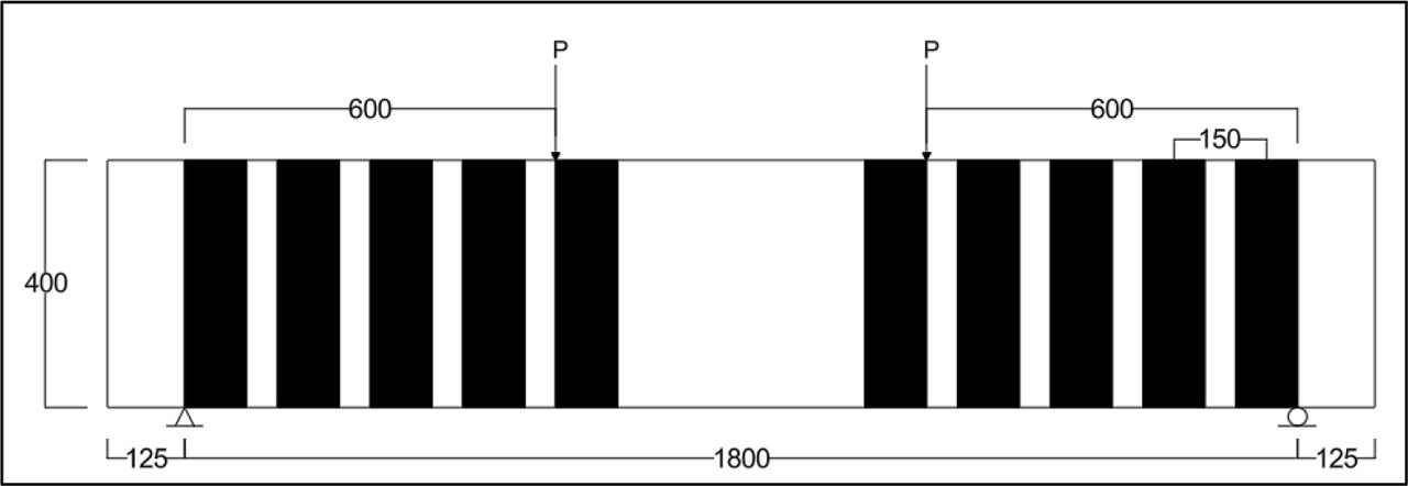
Figure 3:
(RC-CFRP-U-90-100) (all dimensions in mm)
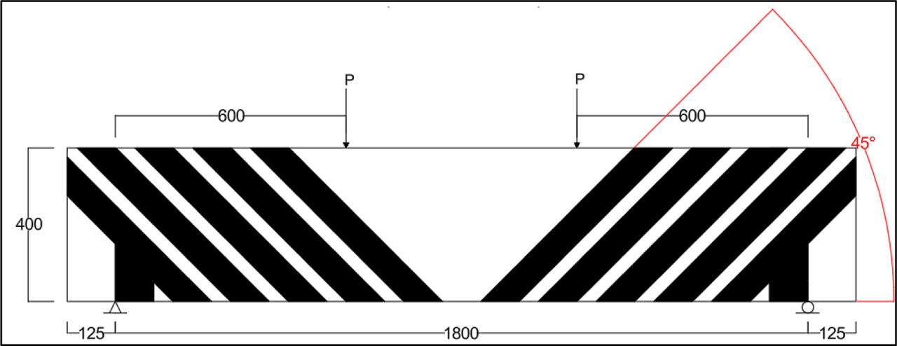
Figure 4:
(RC-CFRP-U-45-100) (all dimensions in mm)
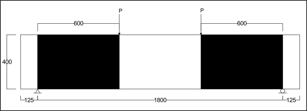
Figure 5:
(RC-CFRP-2side-90-600) (all dimensions in mm)
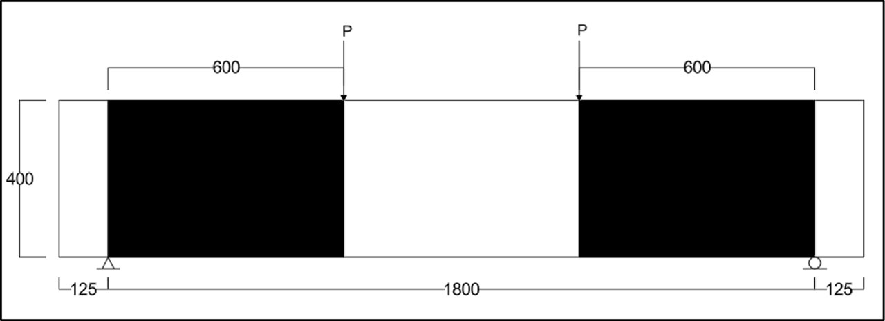
Figure 6:
(RC-CFRP-U-90-600) (all dimensions in mm)
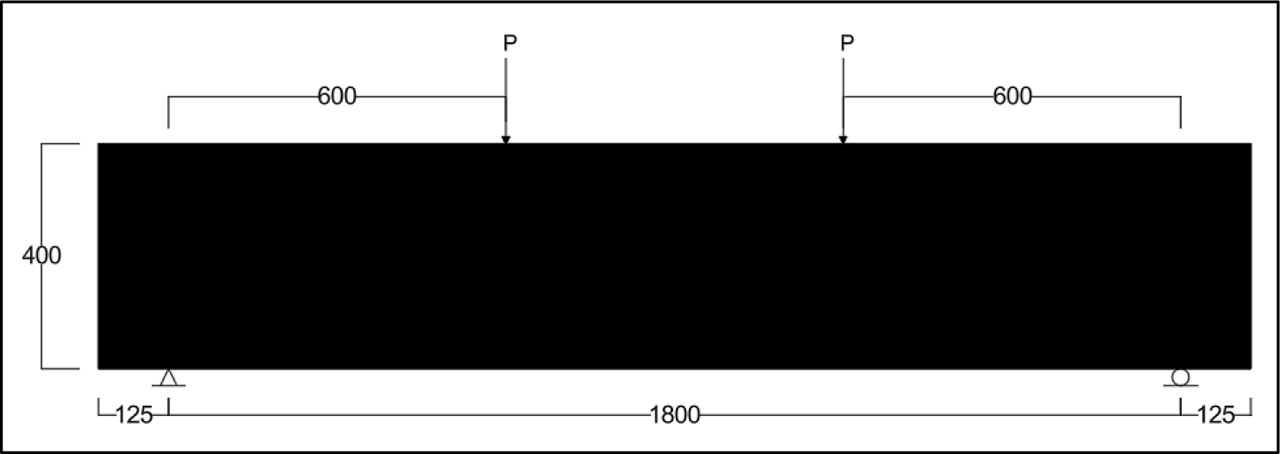
Figure 7:
(RC-CFRP-Full Face) (all dimensions in mm)
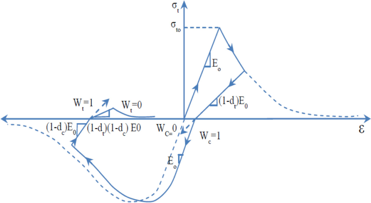
Figure 8:
Uniaxial load cycle (tension-compression-tension) ABAQUS 6.14
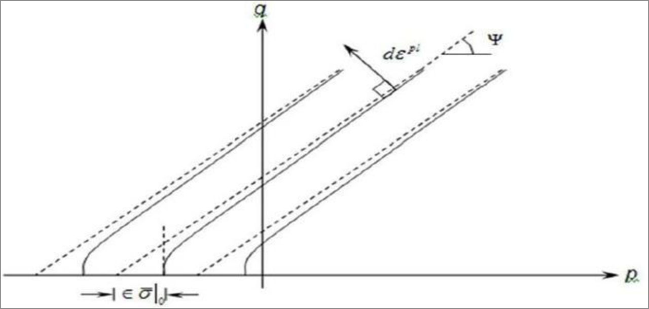
Figure 9:
Flow potentials in the p-q plane CAE (Hibbitt, H., Karlsson, B., & Sorensen, P. 2011)
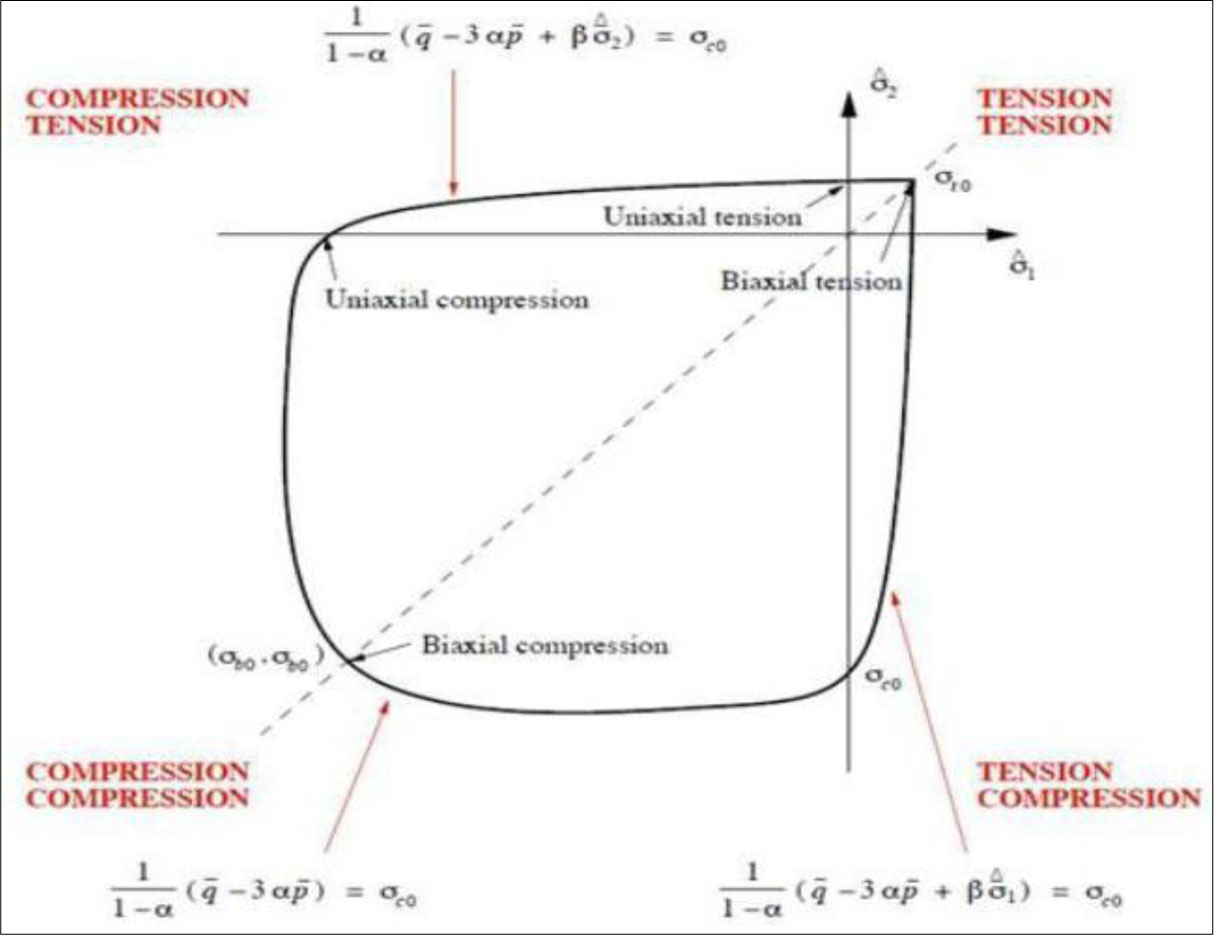
Figure 10:
Yield surface in plane stress (Yu, J., Chen, S., Li, L., & Wang, H. 2011)
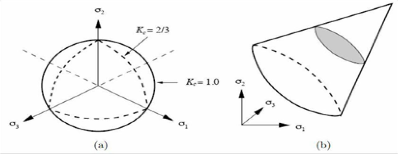
Figure 11:
(a) Drucker-Prager Yield Criteria in the Deviatoric Plane for Different Kc (Hibbitt, H., Karlsson, B., & Sorensen, P. 2011) and (b) Yield Surface in 3D for Kc =1 (Pankaj, P. & Donaldson, C. 2013)
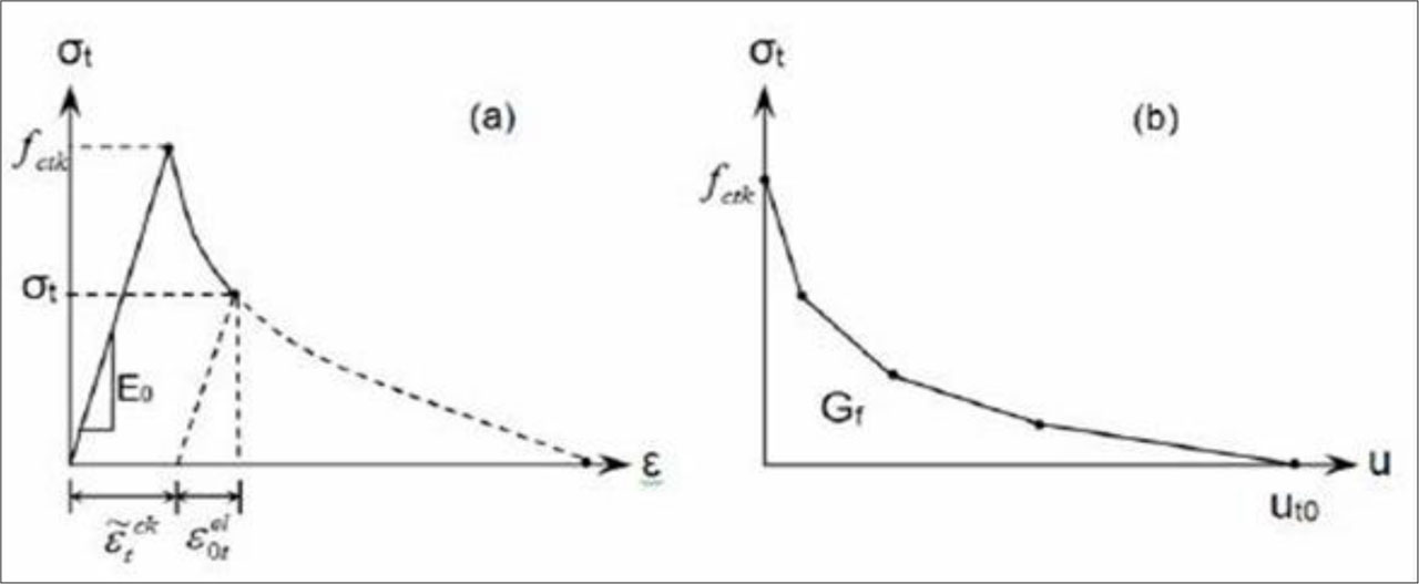
Figure 12:
(a) post-failure tensile behaviour:(a) stress-strain approach;(b) fracture (Hillerborg, A., Modéer, M., & Petersson, P.-E. 1976)
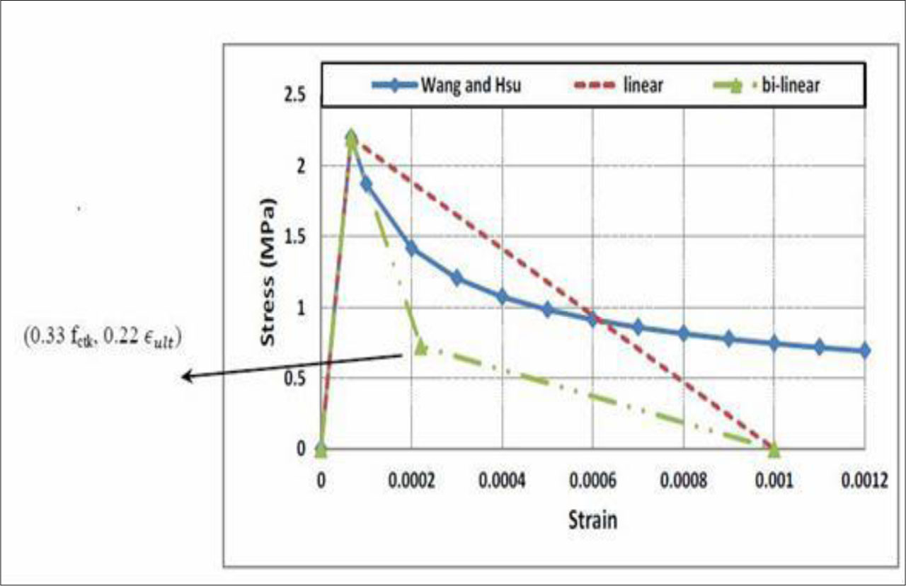
Figure 13:
Uniaxial tensile stress-strain behavior of concrete (Hsu, H.-M., & Wang, W.-P. 2001)
Table 3:
Strength and deformation characteristics of concrete (British Standards Institution, 2004)
| Strength classes for concrete | Analytical relations / Explanation | ||||||||||||||
|---|---|---|---|---|---|---|---|---|---|---|---|---|---|---|---|
| fck (MPa) | 12 | 16 | 20 | 25 | 30 | 35 | 40 | 45 | 50 | 55 | 60 | 70 | 80 | 90 | |
| fck,cube (MPa) | 15 | 20 | 25 | 30 | 37 | 45 | 50 | 55 | 60 | 67 | 75 | 85 | 95 | 105 | |
| fcm (MPa) | 20 | 24 | 28 | 33 | 38 | 43 | 48 | 53 | 58 | 63 | 68 | 78 | 88 | 98 | fcm = fck + 8 (MPa) |
| fctm (MPa) | 1,6 | 1,9 | 2,2 | 2,6 | 2,9 | 3,2 | 3,5 | 3,8 | 4,1 | 4,2 | 4,4 | 4,6 | 4,8 | 5,0 | |
| fctk,0,05 (MPa) | 1,1 | 1,3 | 1,5 | 1,8 | 2,0 | 2,2 | 2,5 | 2,7 | 2,9 | 3,0 | 3,1 | 3,2 | 3,4 | 3,5 | fctk,0,05 = 0,7 × fctm 5% fractile |
| fctk,0,95 (MPa) | 2,0 | 2,5 | 2,9 | 3,3 | 3,8 | 4,2 | 4,6 | 4,9 | 5,3 | 5,5 | 5,7 | 6,0 | 6,3 | 6,6 | fctk,0,95 = 1,3 × fctm 95% fractile |
| Ecm (GPa) | 27 | 29 | 30 | 31 | 33 | 34 | 35 | 36 | 37 | 38 | 39 | 41 | 42 | 44 | |
| εc1 (%0) | 1,8 | 1,9 | 2,0 | 2,1 | 2,2 | 2,25 | 2,3 | 2,4 | 2,45 | 2,5 | 2,6 | 2,7 | 2,8 | 2,8 | |
| εcu1 (%0) | 3,5 | 3,2 | 3,0 | 2,8 | 2,8 | 2,8 | |||||||||
Table 4:
Mechanical properties of CFRP sheet (Sika Wrap®-300C) used in Abaqus modelling
| Property | Value [MPa] | Notes |
|---|---|---|
| E1 | 230,000 | Longitudinal modulus (fiber direction) |
| E2 | 16,000 | Transverse modulus (in-plane, epoxy dominated) |
| E3 | 16,000 | Transverse modulus (through-thickness) |
| G12 | 6,894 | In-plane shear modulus |
| G13 | 6,894 | Shear modulus (fiber–thickness plane) |
| G23 | 4,137 | Shear modulus (transverse plane) |
| ν12 | 0.30 | Poisson’s ratio (longitudinal transverse) |
| ν13 | 0.25 | Poisson’s ratio (longitudinal–through-thickness) |
| ν23 | 0.25 | Poisson’s ratio (transverse–through-thickness) |
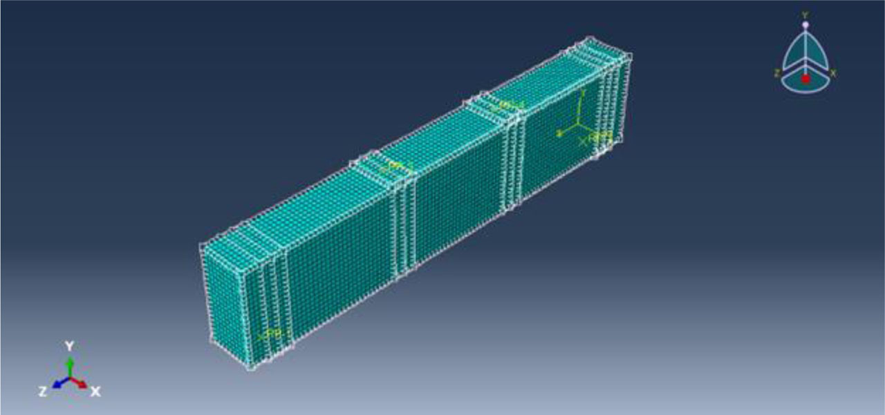
Figure 14:
Mesh for Abaqus model
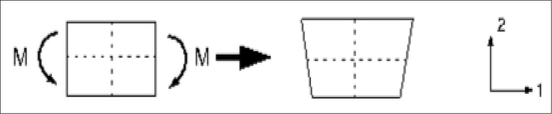
Figure 15:
Linear brick elements undergo pure bending (reduced integration) (Daud, R., Cunningham, L., & Wang, Y. 2015)
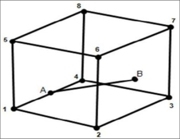
Figure 16:
Element AB is Embedded in (3-D) Continuum Element; Node A is Constrained to edge (1-4), and Node B is constrained to face (2-6-7-3) (Daud, R., Cunningham, L., & Wang, Y. 2015)
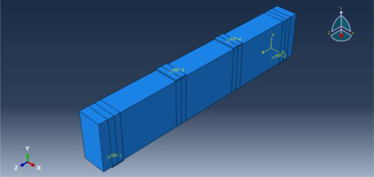
Figure 17:
Boundary Conditions for Beam Model in ABAQUS
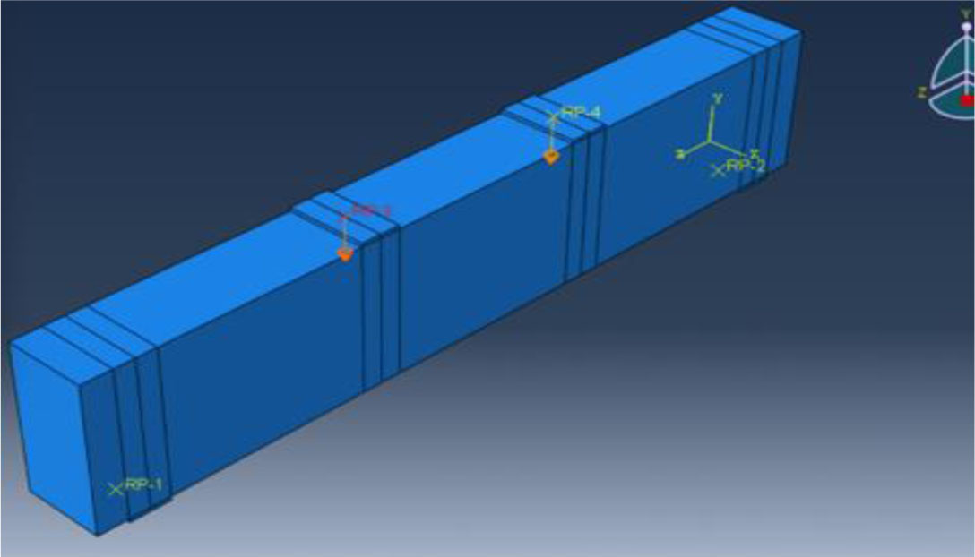
Figure 18:
Specification of Loading Line as Pressure on Beams in ABAQUS
Table 5:
Concrete Compressive Strength Data Used in Numerical Model (Yield stress versus inelastic strain values for concrete under compression)
| Yield Stress [MPa] | Inelastic strain [με] |
|---|---|
| 72.63 | 0.000604 |
| 88.93 | 0.000768 |
| 92.69 | 0.000809 |
| 98.35 | 0.000878 |
| 108.14 | 0.001015 |
| 124.94 | 0.001425 |
| 127.00 | 0.001642 |
| 125.24 | 0.001806 |
| 121.36 | 0.001970 |
| 116.04 | 0.002135 |
| 108.74 | 0.002299 |
| 95.00 | 0.0026001 |
| 80.00 | 0.002910 |
| 65.00 | 0.003200 |
| 50.00 | 0.003500 |
| 35.00 | 0.003790 |
| 20.00 | 0.004200 |
| 10.00 | 0.004580 |
| 0.00 | 0.005000 |
Table 6:
Concrete Tensile Strength Data Used in Numerical Model (Yield stress versus tensile strain values for concrete)
| Yield Stress [MPa] | Inelastic Strain [με] |
|---|---|
| 8.00 | 0.00005 |
| 6.00 | 0.00012 |
| 4.00 | 0.00022 |
| 2.00 | 0.00040 |
| 1.00 | 0.00060 |
| 0.50 | 0.00080 |
| 0.20 | 0.00100 |
Table 7:
Input Parameters for Concrete Plasticity Model in ABAQUS (Material properties and plasticity parameters for concrete)
| Data | Value |
|---|---|
| Poisson ratio | 0.2 |
| Dilation angle (degree) | 36 |
| Eccentricity | 0.1 |
| ϵbo/ϵc | 3.0 |
| kc | 0.667 |
| Viscosity parameter | 0.0001 |
Table 8:
Mechanical Properties of CFRP Sheet Used in Numerical Analysis (Elastic constants and stiffness matrix components of CFRP)
| Data | Value |
|---|---|
| D1111 | 233,289.0 |
| D1122 | 4,111.30 |
| D2222 | 17,235.46 |
| D1133 | 3,029.38 |
| D2233 | 4,237.36 |
| D3333 | 17,202.34 |
| D1212 | 6,894.00 |
| D1313 | 6,894.00 |
| D2323 | 4,137.00 |
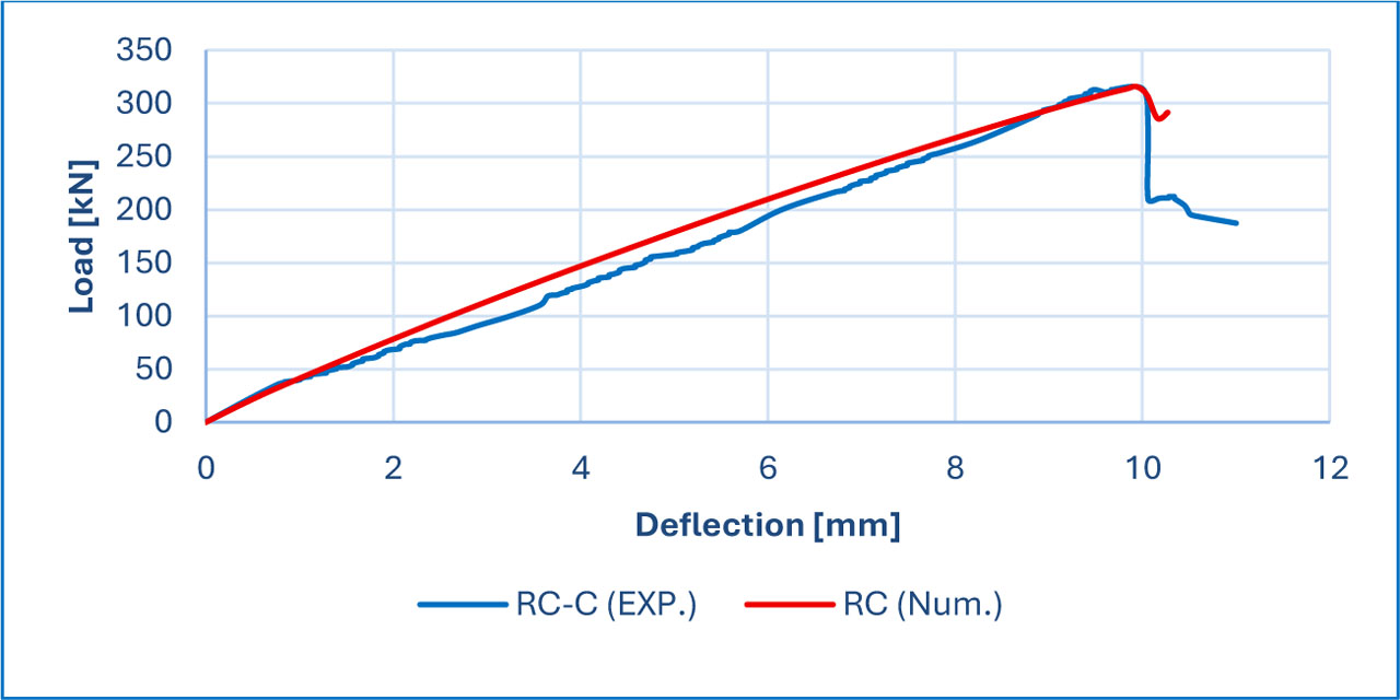
Figure 19:
Validation of (RC) sample
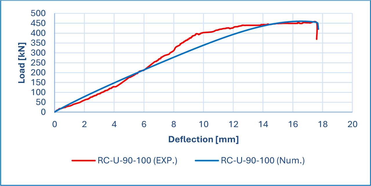
Figure 20:
Validation of (RC-CFRP-U-90-100) sample
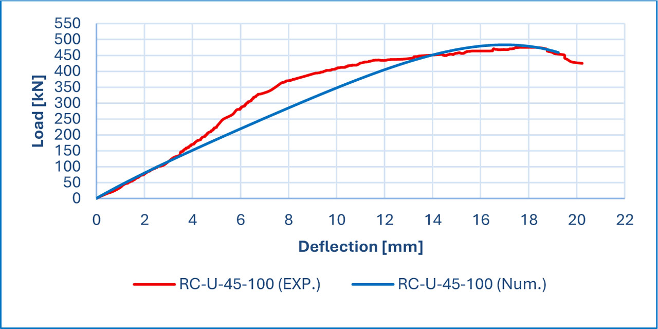
Figure 21:
Validation of (RC-CFRP-U-45-100) sample
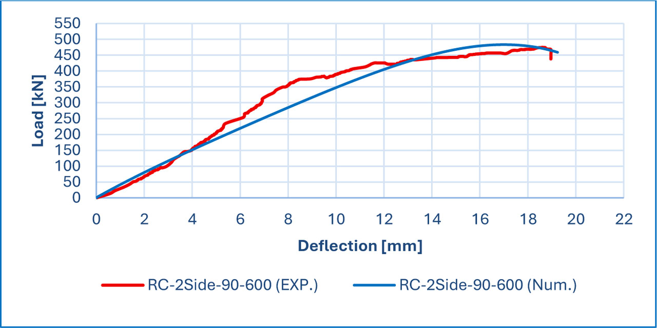
Figure 22:
Validation of (RC-CFRP-2SIDE-90-600) sample
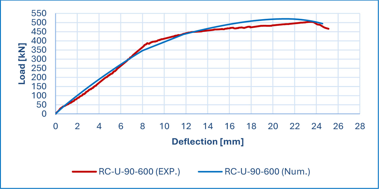
Figure 23:
Validation of (RC-CFRP-U-90-600) sample
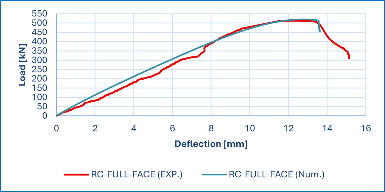
Figure 24:
Validation of (RC-CFRP-FULL-FACE) sample
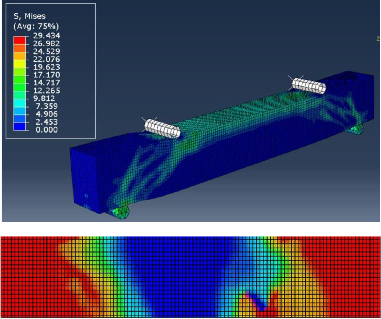
Figure 25:
Von Mises stress distribution and failure pattern of RC-CFRP-FULL-FACE beam model
Table 9:
Summary for the thickness of the beam parameter
| Name of beam | Thickness 0.167mm | Thickness 0.334mm | Load increase [%] rate | ||
|---|---|---|---|---|---|
| Load [kN] | Deflection [mm] | Load [kN] | Deflection [mm] | ||
| RC-CFRP-U-90-100 | 459.90 | 16.54 | 512.24 | 18.34 | 11.38 |
| RC-CFRP-U-45-100 | 481.24 | 16.98 | 541.23 | 18.93 | 12.46 |
| RC-CFRP-2SIDE-90-600 | 483.24 | 16.92 | 543.65 | 18.85 | 12.50 |
| RC-CFRP-U-90-600 | 502.57 | 17.32 | 565.40 | 19.32 | 12.50 |
| RC-CFRP-FULL FACE | 519.46 | 12.73 | 621.75 | 15.27 | 19.69 |
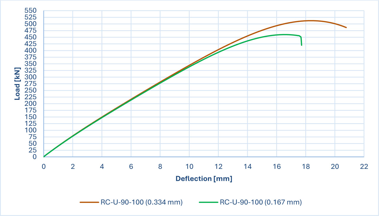
Figure 26:
Thickness of CFRP compares for the (RC-CFRP-U-90-100) sample
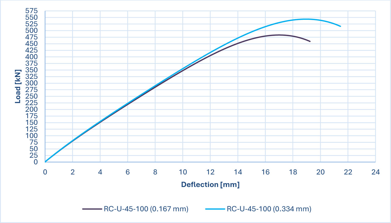
Figure 27:
The thickness of CFRP compared for the (CFRP-U-45-100) sample
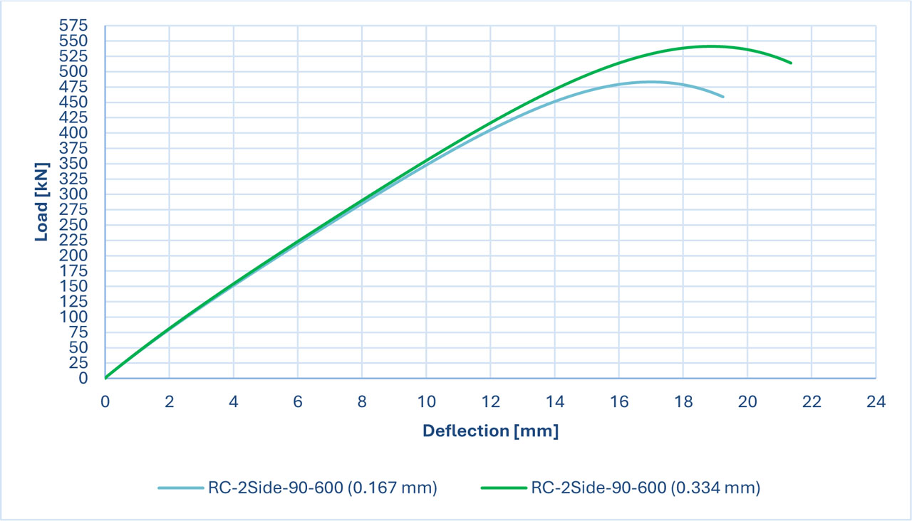
Figure 28:
The thickness of CFRP compared for the (RC-CFRP-2SIDE-90-600) sample
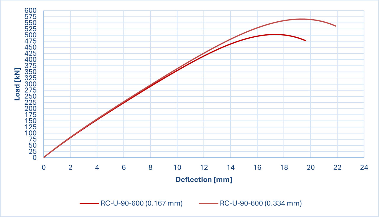
Figure 29:
The thickness of CFRP compared for the (CFRP-U-90-600) sample
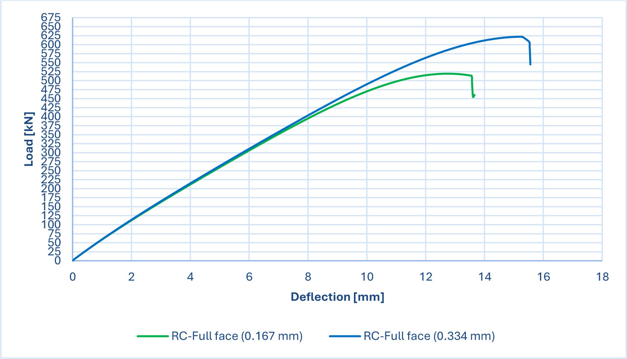
Figure 30:
The thickness of CFRP compared for the (RC-CFRP-FULL-FACE) sample
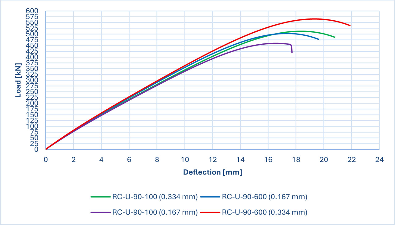
Figure 31:
Load deflection charts for the samples with CFRP spacing parameter
Table 10:
Summary for the thickness of the beam parameter
| Name of beam | Thickness 0.167mm | Thickness 0.334mm | Load increase rate [%] | ||
|---|---|---|---|---|---|
| Load [kN] | Deflection [mm] | Load [kN] | Deflection [mm] | ||
| RC-CFRP-U-90-100 | 298.94 | 10.17 | 352.74 | 12.51 | 18 |
| RC-CFRP-U-45-100 | 361.70 | 12.63 | 410.45 | 13.78 | 13.48 |
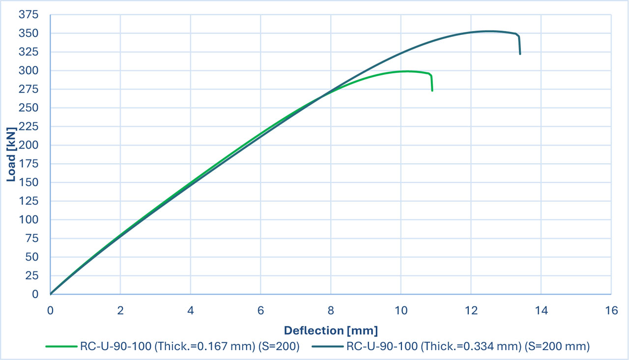
Figure 32:
Load deflection charts for the (RC-U-90-100) specimen with CFRP spacing (200 mm)
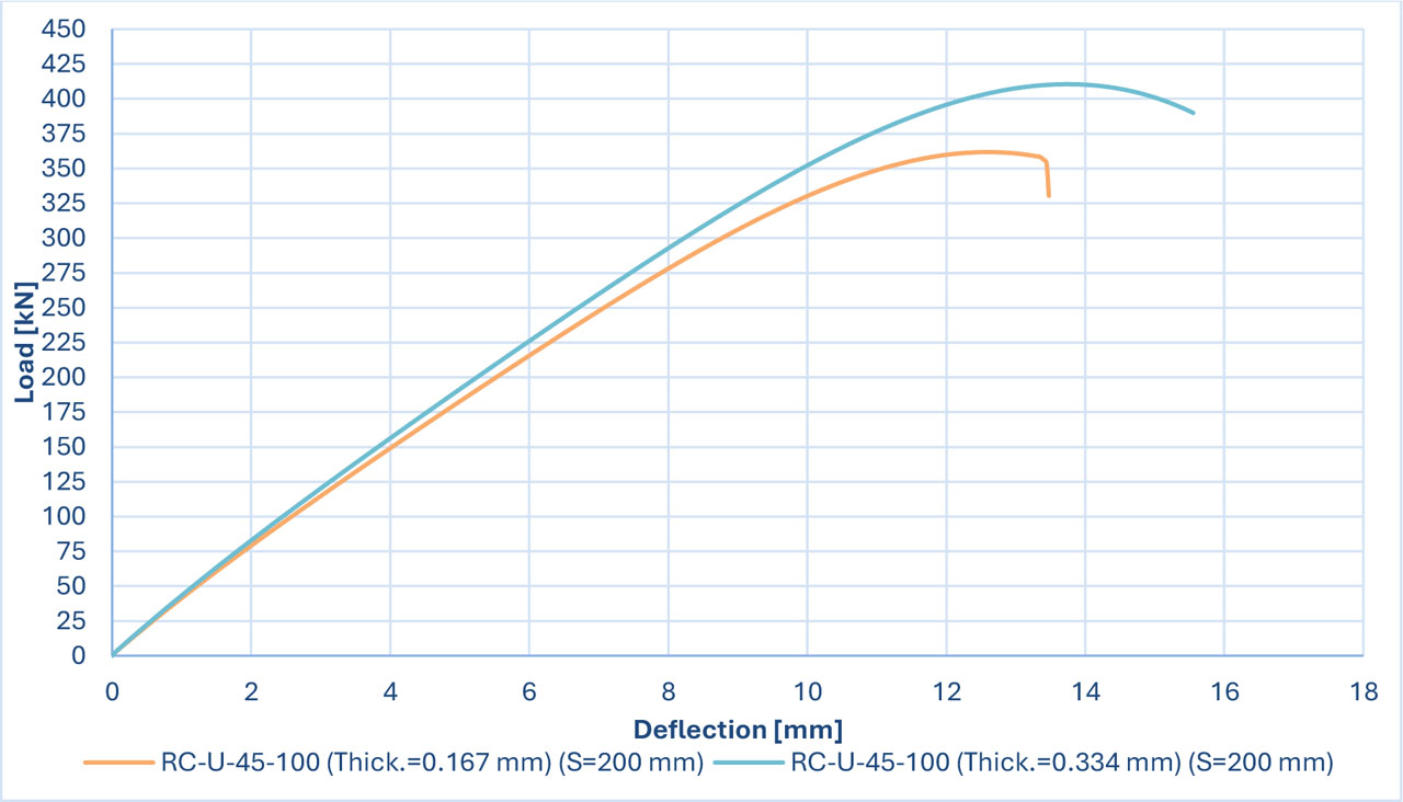
Figure 33:
Load deflection charts for the (RC-U-45-100) specimen with CFRP spacing (200 mm)
Table 11:
Summary for the thickness of the beam parameter
| Name of beam | Thickness 0.167mm | Thickness 0.334mm | Load increase rate [%] | ||
|---|---|---|---|---|---|
| Load [kN] | Deflection [mm] | Load [kN] | Deflection [mm] | ||
| RC-CFRP-U-90-100 | 459.90 | 16.54 | 512.24 | 18.34 | 11.38 |
| RC-CFRP-U-45-100 | 483.24 | 17.05 | 543.65 | 19.01 | 12.46 |
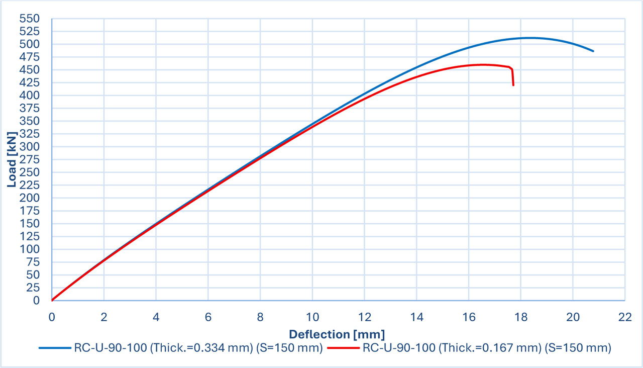
Figure 34:
Load deflection charts for the (RC-U-90-100) specimen with CFRP spacing (150 mm)
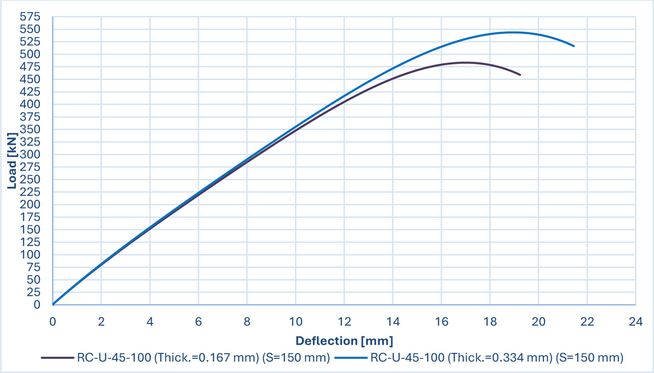
Figure 35:
Load deflection charts for the (RC-U-45-100) specimen with CFRP spacing (150 mm)
Table 12:
Observed versus estimated shear contributions of CFRP in the strengthened specimens
| Specimens | CFRP Contribution Determined by the Subtraction approach: [kN] | CFRP Contribution According to ACI 440.2R-17: [kN] | CFRP Contribution According to CNR-DT-215-2018: [kN] | CFRP Contribution According to TR-55 (CS, 2013): [kN] |
|---|---|---|---|---|
| RC-U-90-100 | 70.110 | 73.132 | 57.234 | 63.593 |
| RC-U-45-100 | 80.615 | 103.698 | 57.234 | 89.934 |
| RC-2side-90-600 | 80.900 | 109.698 | 85.851 | 95.390 |
| RC-U-90-600 | 95.090 | 109.698 | 85.851 | 95.390 |
| RC-Full-Face | 99.120 | 109.698 | 85.851 | 95.390 |