

Ultra-High-Performance Concrete (UHPC) has emerged as a cutting-edge material in structural engineering, primarily due to its outstanding mechanical properties, including superior compressive and tensile strength, enhanced durability, and excellent resistance to environmental degradation. These features make UHPC particularly suitable for critical applications such as seismic zones and long-span structures. However, its widespread use is often limited by the high content of Portland Cement (PC), which contributes significantly to both cost and carbon dioxide emissions. Recent advancements have sought to address this issue through partial replacement of PC with sustainable materials such as Ground Granulated Blast Furnace Slag (GGBS) and Waste Glass (WG), as demonstrated by Ismaeel et al. (2024), who reported improved mechanical properties at a 10% replacement level.
Given UHPC’s dense matrix and low porosity, integrating Fiber Reinforced Polymer (FRP) systems particularly Carbon Fiber Reinforced Polymer (CFRP) has become an attractive method to further enhance its structural performance. CFRP offers a unique combination of high tensile strength, lightweight properties, corrosion resistance, and ease of application, making it ideal for structural retrofitting, especially in areas subjected to tensile stresses or complex loading conditions. Despite the benefits, the bond behaviour between CFRP and UHPC remains underexplored, presenting a critical gap in research that this study seeks to address.
According to ASTM International (2017), Nematollahi (2012), Mishra & Singh (2019), Azreen et al. (2018), Azreen et al. (2020), and Yazici et al. (2010), Ultra-high-performance concrete (UHPC) is an advanced type of concrete that integrates Fibers and cement, resulting in a material with exceptional compressive strength. Du et al. (2021), Ganesh & Murthy (2019), Yoo et al. (2016), Bajaber & Hakeem (2021), Imam et al. (2022), Habert et al. (2013), Daniel et al. (2002), Mueller et al. (2016), and Alkaysi et al. (2016) stated that when compared to conventional concrete, it has superior resistance against compression, is denser, and is efficient in managing tension. Up to 300 times more energy can be managed by UHPC than by regular high-performance concrete (HPC). According to Wang et al. (2015) High-strength concrete is about three to sixteen times tougher than ordinary concrete when exposed to pressure. Its excellent performance, flexibility, and strong features make UHPC valuable in areas where buildings are exposed to earthquakes according to Yoo et al., (2016) and Bajaber & Hakeem, (2021) Schmidt & Fehling, (2005) say Avoiding replacements allows us to be more sustainable in the long term. According to Shi et al. (2015) UHPC is produced using much less water than regular cement (a water-to-cement ratio ranging from 0.15 to 0.25). Because there’s little water in the mixture, superplasticizers are used to help keep the cement in workable shape. This action helps the particles blend well and advances how the concrete moves, Hirschi & Wombacher, (2008) The most common materials used in UHPC are silica fume and ordinary Portland cement (OPC). Between 2018 and 2022, the global market for UHPC grew steadily at over 7% each year according to Maida, (2022). In recent years, more people have become aware of the environmental problems linked to OPC, leading to a rising interest in finding eco-friendlier alternatives for making concrete as in Park et al., (2021). The use of WG and GGBS, as explored by Ismaeel et al. (2024), demonstrated that a 10% substitution improves both compressive and tensile strength, although higher levels may compromise performance.
CFRP systems have demonstrated exceptional potential in retrofitting RC structures, especially where shear or flexural deficiencies exist. Studies have shown that externally bonded CFRP laminates and near-surface mounted (NSM) CFRP rebars significantly improve structural behaviour. For instance, Kazem and Abd Al-Zahra (2024) reported increases in ultimate load capacity by up to 156% for laminated systems and 294.17% for NSM systems in RC slabs with openings. Additionally, CFRP laminates were found to reduce deflection more effectively, while NSM rebars enhanced overall load-bearing capacity.
In beam applications, hybrid strengthening techniques using CFRP plates combined with anchorage (U-wraps of CFRP, GFRP, or BFRP) have yielded further improvements. Al-Kamaki (2024) observed a 45% increase in load capacity and 64% reduction in deflection with CFRP plate + U-wrap combinations, though at the expense of ductility. This trade-off highlights the importance of proper anchorage and bonding to ensure effective stress transfer and delayed debonding failure.
In retrofitting systems incorporating fibre-reinforced polymers (FRP), the variability in material properties and bonding behaviour further complicates the development of standardized design guidelines. Using FRP (fibre-reinforced polymer) strips or strips attached to the surface of reinforced concrete (RC) structures has shown to be a very effective way to strengthen them. In fact, it often works better than older, more traditional methods. FRP materials are lightweight, don’t rust easily, and have strong mechanical properties. They are also easy to apply by hand, which makes it possible to reinforce different parts of a structure in many shapes and setups as explained in Al-Allaf, M. H., Weekes, L., & Augusthus-Nelson, L. (2015), Lateef, H. E., Al-Allaf, M. H., & Daud, R. A. (2024) and Al-Allaf, M. H., Daud, R. A., & Daud, S. A. (2024).
CFRP also enhances torsional performance. Zarzour et al. (2024) demonstrated that vertical CFRP configurations improved torsional strength by 109.52%, while inclined configurations achieved 61.90% improvements. For dynamically loaded beams, Koteš et al. (2013) found that CFRP lamellas significantly improved stiffness, increased natural frequencies, and reduced vibration amplitudes.
Despite extensive research on CFRP in normal-weight concrete (NWC), few studies have focused on CFRP-UHPC interaction. However, preliminary experimental data indicate that UHPC’s dense matrix supports superior bonding with CFRP. This is consistent with Ercan, Arısoy, and Hökelekli (2018), who found that bonding CFRP strips to the bottom flange of steel-concrete composite beams improved flexural strength by up to 35.4% with three layers, owing to the high elastic modulus of CFRP (230 GPa) and effective stress transfer even after partial debonding.
FRP-strengthened normal-weight concrete beams have been widely analysed to assess their performance under shear loading, considering factors such as strengthening configurations and bond length as explained in Wu et al., (2018) and Andrade & Torres, (2013), shear span-to-depth ratio Wu et al., (2018), size effect (Xue et al., (2020) and Larsen et al., (2017), shear reinforcement ratio, FRP orientation and width Arunothayan et al., (2020), NPCA, (2013),Wille & Naaman, (2012) and Ghasemi et al., (2016), and loading conditions Tanaka et al., (2013) and Kalny et al., (2016). Despite extensive research on FRP reinforcement in NWC, limited studies have focused on its bond behaviour in UHPC. This study aims to address this gap by experimentally investigating the local bond behaviour of FRP reinforcement in UHPC. The test results show that UHPC provides superior bonding strength. Moreover, this study investigates the use of epoxy-adhered carbon fibre reinforced polymer (CFRP) systems for enhancing UHPC beams, providing fresh perspectives on their efficiency and possible areas of implementation.
The study examines how UHPC beams behaved when reinforced with CFRP sheet s resisting shear forces. The program included six UHPC specimens that were all created and loaded the same way to study how reinforcement affects the overall shear resistance.
This part explains the specimens used during the study.
All specimens had beams of the same geometry and concrete grade, resulting in equal compressive strength in all cases. The choices for shear reinforcement in the beams differed a lot. In the control specimen, known as RC-C Beam, there was a tiny internal reinforcement to resist shear, with only two shear links added close to the supports and without external CFRP treatment.
Different types of CFRP reinforcement were used on the other beams to find out which was best. This specimen, RC-CFRP-U-90-100 Beam, included U-shaped CFRP strips joined with epoxy and arranged perpendicular (90 degrees) to the beam axis from the beam’s center support to the load point. These strips were spaced 150 mm apart center-to-center. A similar beam, the RC-CFRP-U-45-100, used the same width and spacing of CFRP strips but oriented at a 45-degree angle, offering a different shear reinforcement configuration. Another design, the RC-CFRP-2SIDE-600 Beam, employed wide (600 mm) epoxy-bonded CFRP strips applied to both sides of the beam, again extending from the center point of the support to the load point. The RC-CFRP-U-90-600 Beam followed a similar pattern but with U-shaped strips at a 90-degree angle on each side. Lastly, the RC-CFRP-FULL FACE Beam utilized full-face epoxy-bonded CFRP strips, also 600 mm wide, covering the entire side surfaces between the support and load center to maximize shear strengthening.
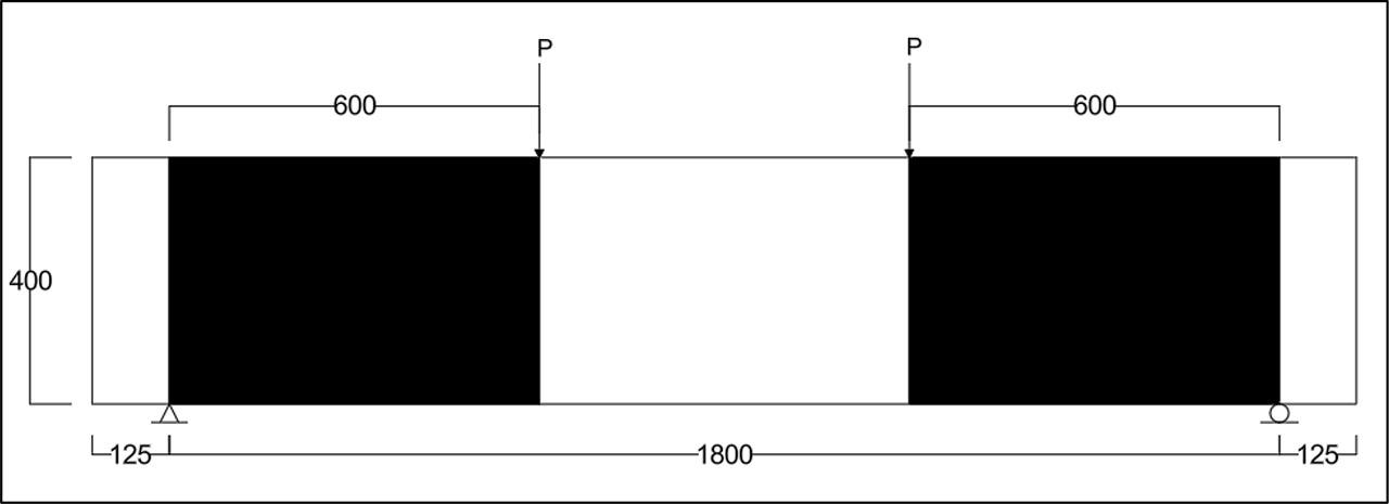
All beams were uniformly dimensioned at 200 mm width, 400 mm depth, and 2050 mm length as illustrated in Figure 1. The testing setup involved simply supported specimens subjected to four bending point, with supports placed 125 mm from the beam ends. The loading was displacement-controlled and monotonically applied to precisely capture the shear behaviour. The shear span-to-effective depth ratio (a/d) was set at approximately 1.63 to promote shear failure modes. Reinforcement included three 16 mm diameter deformed steel bars at the bottom and two at the top, we added only two shear links (10 mm) diameter reinforcing steel bars were used to ensure the main reinforcement was distributed in the appropriate place, noting that they were placed outside the supports to ensure that they did not contribute to the shear resistance, maintaining a longitudinal steel ratio of 1.67% in both layers. This flexural reinforcement was intentionally designed to prevent flexural failure, allowing the study to focus solely on the shear resistance provided by the CFRP strengthening. The effective depth was measured at 367 mm, with a concrete cover of 25 mm, ensuring consistent protection for the steel bars.
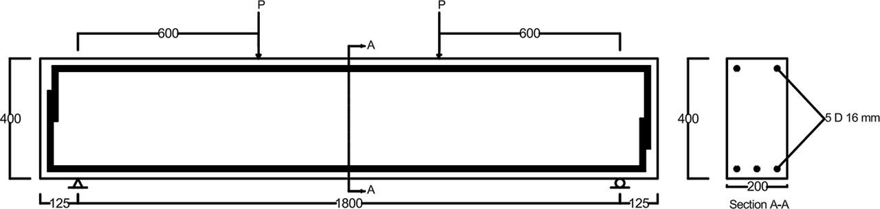
Dimension and reinforcement details of specimens (all dimensions in mm).
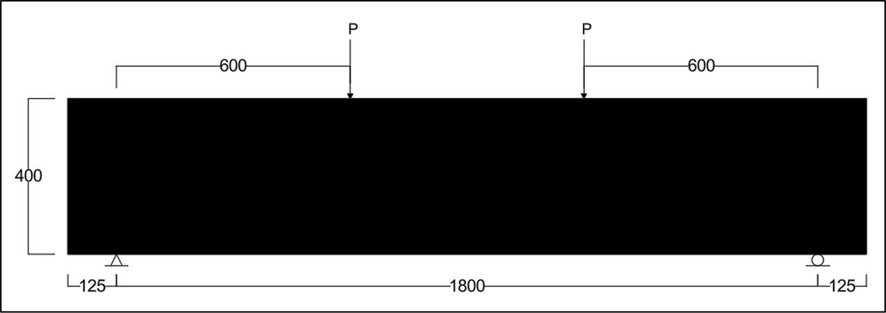
In this study, CFRP was employed in various shear strengthening arrangements, as outlined in Table 1. The first beam, serving as a control specimen, was tested without CFRP reinforcement, as shown in Figure 2. The CFRP strips used for shear strengthening had a width of 100 mm, with a center-to-center spacing of 150 mm. In one configuration, the strips were oriented at 90 degrees, as illustrated in Figure 3, while in another, they were placed at a 45-degree angle, as shown in Figure 4. For the two-sided strengthening scheme, wider CFRP strips measuring 600 mm in width were bonded to both sides of the beam, as shown in Figure 5. The U-shaped configuration featured 600 mm-wide CFRP strips attached to the tension face at the bottom and to both side faces, as seen in Figure 6. Similarly, a closed-shaped arrangement involved wrapping CFRP strips around all faces of the beam, as illustrated in Figure 7. CFRP strips were installed along the shear span, starting from the points of support to the locations where the loads were applied on both sides.
CFRP reinforcement configurations and strengthening.
| Sample | CFRP strengthening type at each side | CFRP orientation |
|---|---|---|
| RC-C | Without | 0 |
| RC-U-90-100 | U-shape,100 mm width,150mm spacing c/c | 90° |
| RC-U-45-100 | U-shape,100 mm width,150mm spacing c/c | 45° |
| RC-2side-90-600 | 2-sided - shape,600 mm width | 90° |
| RC-U-90-600 | U-shape,600 mm width | 90° |
| RC-Full-face | Full face | 90° |
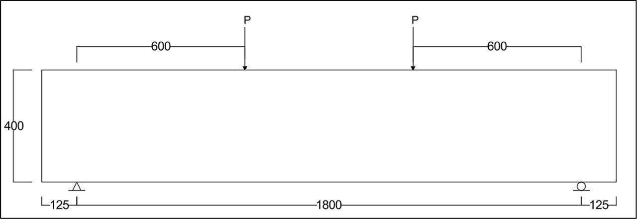
(RC-C) control specimen (all dimensions in mm).
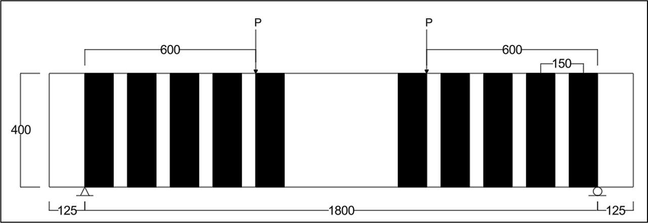
(RC-CFRP-U-90-100) (all dimensions in mm).
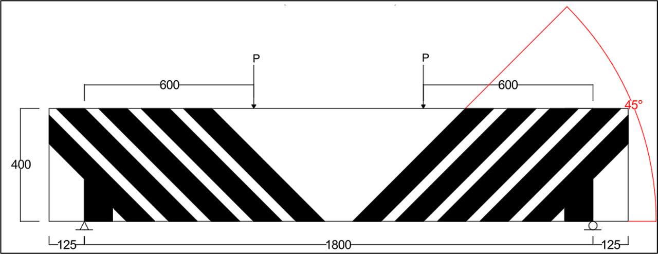
(RC-CFRP-U-45-100) (all dimensions in mm).

(RC-CFRP-2side-90-600) (all dimensions in mm).
(RC-CFRP-U-90-600) (all dimensions in mm).
(RC-CFRP-full face) (all dimensions in mm).
UHPC was developed using a carefully engineered combination of cement, silica fume, fly ash, superplasticizer, fine sand, and water. The formulation was optimized by controlling the particle size distribution, as well as the physical and chemical properties of the components, to achieve a target 28-day concrete strength of 126.97 N/mm2. All specifications for the materials used to produce the models were included based on the laboratory tests shown in Tables 2 to Table 7. Details of the specific mix design can be found in Table 8. All UHPC samples were prepared from a single production batch to maintain consistency. To assess the key mechanical properties of the material, namely, uniaxial compressive strength, flexural strength, density, and Young’s modulus, each batch included twelve cube specimens measuring 150 mm and six prism specimens sized 100 × 100 × 400 mm, as listed in Table 9. In parallel, three steel deformed bars were tested under uniaxial tension to determine their mechanical performance, with results summarized in Table 10. Properties of the CFRP strips and the adhesive material used in this study are presented in Table 11. The bonding of CFRP strips to the concrete surface was achieved using Sikadur®-330, a two-component epoxy adhesive consisting of Part A (white) and Part B (black), mixed at a 4:1 ratio by volume. Table 12 provides the detailed physical and mechanical characteristics of this bonding agent. Prior to application of the CFRP, the concrete surface underwent mechanical preparation using a grinding tool to ensure a roughened profile that enhances bonding. This was followed by a thorough cleaning process to remove any loose dust or debris. The full composition of the concrete mix is reiterated in Table 8 for reference. To evaluate the performance of the steel reinforcement, three longitudinal steel bar specimens were subjected to uniaxial tensile testing. The mean mechanical properties obtained from these tests are summarized in Table 10.
Chemical composition and main compounds of sulphate-resisting Portland cement.
| Oxide composition content | Content [%] | Limits of Iraqi standard No.5/2019 |
|---|---|---|
| CaO | 62.15 | --- |
| SiO2 | 19.88 | --- |
| Al2O3 | 3.5 | --- |
| Fe2O3 | 4.7 | --- |
| MgO | 3.23 | <5.00 |
| SO3 | 1.84 | <2.50 |
| Na2O | 0.26 | |
| K2O | 0.51 | |
| L.O.I. | 1.25 | <4.00 |
| Insoluble residue | 0.80 | <1.5 |
| Lime saturation factor | 0.928 | 0.66-1.02 |
| Main compounds (Bogue's equations) | ||
| C3S | 54.51 | --- |
| C2S | 18.77 | --- |
| C3A | 1.51 | <3.50 |
| C4AF | 14.14 | --- |
Physical properties of cement.
| Physical properties test | Test results | Limits of Iraqi standard No.5/2019 | |
|---|---|---|---|
| Surface area (Blaine) [m2/kg] | 282 | ≥250 | |
| Setting time (Vicat) | Initial setting, hrs: min. | 3:51 | ≥ 45 min. |
| Final setting, hrs: min. | 6:20 | ≤ 10 hrs. | |
| Compressive strength [MPa] | 2 days | 23.7 | ≥20.00 |
| 28 days | 43 | ≥42.5 | |
| Soundness (Autoclave) [%] | 0.13 | ≤0.8 | |
Fine aggregate grading.
| Sieve size [mm] | Cumulative passing [%] | Iraqi standard No.45/1984 zone (2) |
|---|---|---|
| 10 | 100 | 100 |
| 4.75 | 91 | 90 - 100 |
| 2.36 | 86 | 75 - 100 |
| 1.18 | 72 | 55 - 90 |
| 0.6 | 51 | 35 - 59 |
| 0.3 | 26 | 8 - 30 |
| 0.15 | 9 | 0 - 10 |
| Fineness modulus | 2.68 | --- |
Some properties of fine aggregate.
| Physical properties | Test results | Iraqi standard No.45/1984 |
|---|---|---|
| Specific gravity SSD | 2.66 | -- |
| Bulk density [kg/m3] | 1750 | -- |
| Sulphate content [%] | 0.16 | ≤ 0.5 % |
| Absorption [%] | 0.63 | -- |
Chemical analysis of silica fume.
| NO. | Components | Silica fume [%] | ASTM C1240 limitations |
|---|---|---|---|
| 1 | CaO | 1.22 | |
| SiO2 | 91.05 | ≥ 85 | |
| Al2O3 | 0.018 | -- | |
| Fe2O3 | 0.012 | -- | |
| MgO | 0.01 | -- | |
| SO3 | 0.225 | -- | |
| Na2O | 0.205 | -- | |
| K2O | 0.155 | -- | |
| Loss on ignition | 2.975 | ≤ 6 | |
| Moisture content | 0.68 | ≤ 3 | |
| 2 | Activity index with Portland cement at 7 days | 132.4 | ≥ 105 |
| Percent retained on 45μm (No. 325) sieve, max. [%] | 7 | ≤ 10 | |
| Surface area (Blaine) [m2/kg] | 15000 | ≥ 15000 |
Chemical composition and main compounds of fly ash.
| Compounds | Fly ash class F |
|---|---|
| SiO2 | 55 |
| Al203 | 26 |
| Fe2O3 | 7 |
| CaO (Lime) | 9 |
| MgO | 2 |
| SO3 | 1 |
Mix proportions and compressive strength results.
| Mixes all in [kg/m3] | Fine sand | Sulphate-resisting Portland cement | Water | Superplastizer | Silica fume | Fly ash | Compressive strength [MPa] 28 days |
|---|---|---|---|---|---|---|---|
| 1 | 1070 | 963 | 204 | 32 | 107 | 0 | 74.81 |
| 2 | 1070 | 963 | 200 | 32.5 | 107 | 192.6 | 92.9 |
| 3 | 1070 | 970 | 184 | 33.4 | 107 | 192.6 | 126.97 |
Summary of concrete mechanical characteristics.
| Compressive strength [MPa] | Flexural strength [MPa] | Elastic modulus [MPa] | Density of concrete [kg/m3] |
|---|---|---|---|
| 126.97 | 22.756 | 50619.044 | 2522 |
Mechanical characteristics of steel reinforcement bars.
| Diameter [mm] | Yield strength [MPa] | Yield strain [με] | Ultimate strength [MPa] | Ultimate strain [με] | Elastic modulus [MPa] |
|---|---|---|---|---|---|
| 16 | 582.4 | 2632 | 687.9 | 130000 | 200000 |
Mechanical properties of CFRP sheets (strips)
| Modulus of elasticity [GPa] | Tensile strength [MPa] | Strain at failure [%] | Thickness [mm] | Width [mm] |
|---|---|---|---|---|
| 230 | 4000 | 1.7 | 0.167 | 500 |
Mechanical and physical properties of Sikadur®-330 technical data sheet.
| Properties | Tensile strength [MPa] | E- modulus [GPa] | Bond strength [N/mm2] | Mixing ratio |
|---|---|---|---|---|
| Value | 30 | 4500 | > 4 | A: B = 4: 1 by weight |
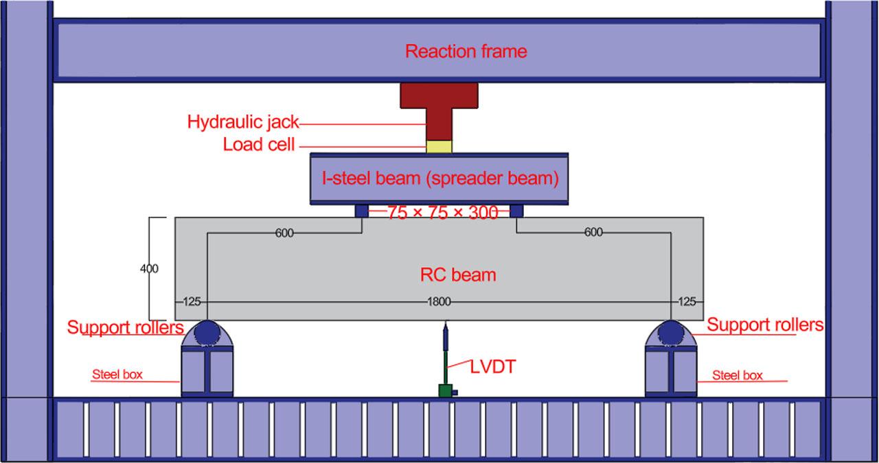
A four-point bending test configuration was utilized, as depicted in Figure 8. The applied load was monitored using a 2000 kN load cell connected to a hydraulic jack, with the load delivered steadily through a spreader beam. To mitigate the risk of concrete crushing at the support zones, steel rollers were welded onto a steel box measuring 500 mm in length and 100 mm in width, which was positioned beneath the specimen. The beam was supported at two locations, each featuring a 25 mm diameter steel roller placed on a 100 mm wide steel plate. To ensure even load distribution and minimize stress concentration at the loading points, another steel roller was welded onto the steel plate, and a steel bearing block, 300 mm in length and 75 mm in width, was set directly above the concrete surface at the load application area. The tested beams had a clear span of 1800 mm, and rubber padding was placed at the supports to prevent localized crushing of the concrete. The setup was designed to evaluate the shear and flexural behavior of reinforced concrete beams under applied loads. The beams were subjected to a gradual load application at a rate of 2 kN/10 sec until failure occurred. A high-precision data acquisition system continuously recorded load-displacement responses during testing. Strain gauges were affixed to the steel and CFRP strips and to measure strain variations. At the same time, linear variable displacement transducers (LVDTs) monitored deflections at critical points along the beam.
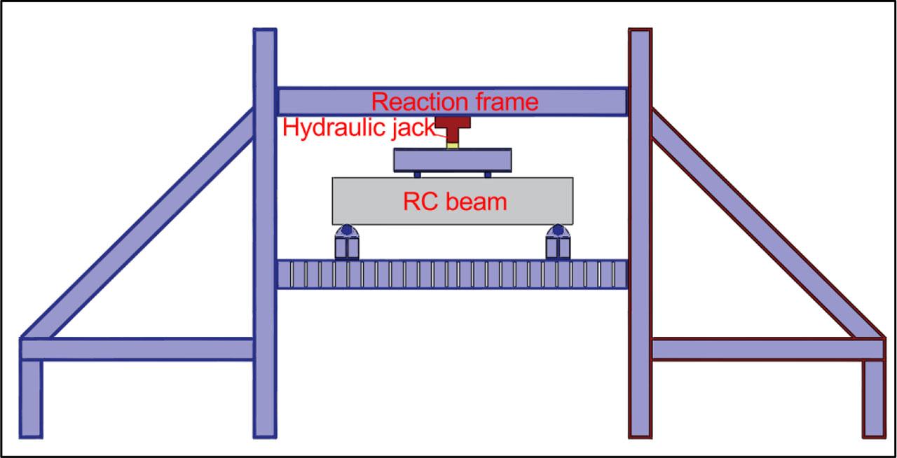
Specimen test setup.
To monitor strain distribution along the central reinforcing bar in the bottom layer of each UHPC specimen, seven unidirectional strain gauges were installed. These gauges, manufactured by Tokyo Sokki Company, had a gauge factor of 2.12 ± 1%, a resistance of 120 ± 0.5 ohms, and a gauge length of 6 mm. The sensors were precisely positioned along the midspan of the beam, as illustrated in Figure 9. Figure 10 displays the arrangement of strain gauges used to monitor the CFRP reinforcement throughout the testing process, highlighting their positions along the span from the load application point to the support. For this task, the FLA-5-11 strain gauge was utilized, which is designed to measure strain in three perpendicular directions. These gauges were installed in a vertical orientation and feature a gauge factor of 2.12% and a gauge length of 5 mm. This setup was uniformly applied to all specimens strengthened with UHPC. A single linear variable differential transformer (LVDT) was employed to capture the vertical displacement at the specimen's midpoint. This setup, illustrated in Figure 11, utilized one LVDT specifically for measuring these deflections.
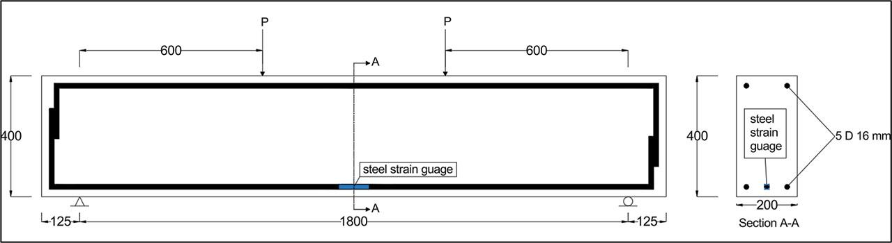
Steel strain gauge location.
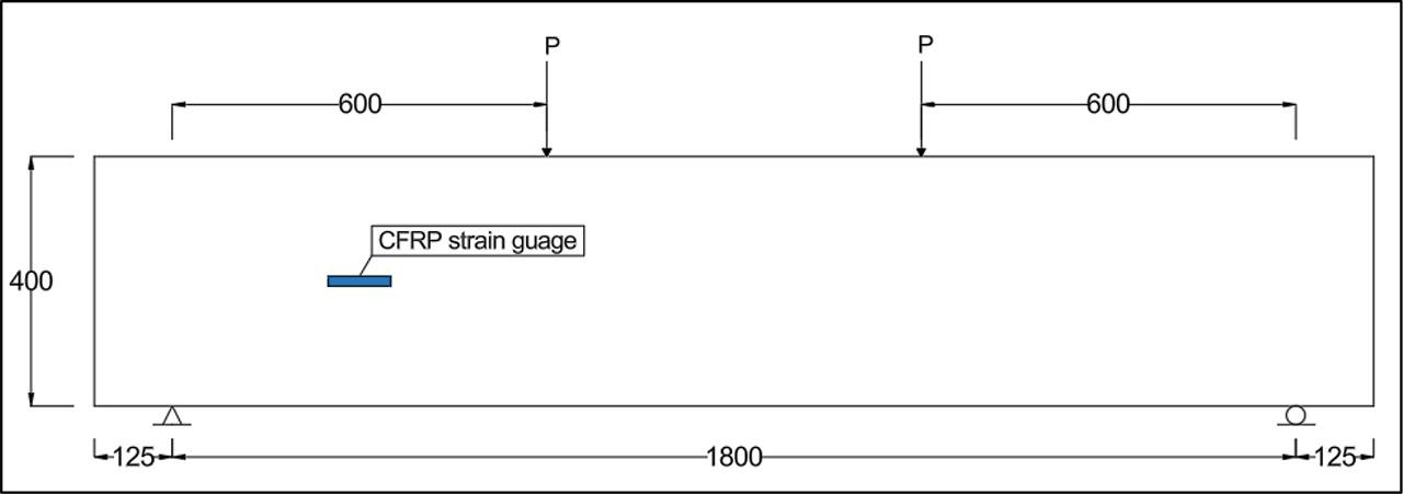
CFRP strain gauge location.
Linear variable differential transformer (LVDT).
Table13 provides a comprehensive overview of the shear strength characteristics of the tested samples, detailing the maximum shear strength, peak mid-span displacement, CFRP strengthening type and orientation, and concrete contribution to shear (Vc), CFRP contribution to shear (Vf), total shear strength (Vt), and the observed failure modes. Within the UHPC series, the addition of CFRP reinforcement led to notable shear strength gains: U-shaped specimens with a 100 mm width oriented at 90 degrees experienced a 44.765% increase; those oriented at 45 degrees showed a 51.473% improvement; two-sided U-shaped specimens with a 600 mm width at 90 degrees saw a 51.655% boost; single-sided U-shaped specimens of the same width and orientation achieved a 60.716% rise; and fully reinforced face-shaped specimens recorded the highest enhancement at 63.288%. Analysing the peak shear failure loads of specimens strengthened with CFRP retrofitting against the control group clearly underscores the effectiveness of CFRP retrofitting in elevating the shear capacity of UHPC beams. Figure 12 visually illustrates these improvements in shear strength due to CFRP application, relative to their corresponding control samples. Overall, the findings confirm that CFRP reinforcement significantly enhances the shear behavior of UHPC beams under the tested loading conditions.
Total shear capacity, type of failure, and other results.
| Sample | Total load [kN] | Vt [kN] | First crack [kN] | Maximum deflection [mm] | CFRP strengthening type at each side | CFRP orientation | Vc [kN] | Vf [kN] |
|---|---|---|---|---|---|---|---|---|
| RC-C | 313.23 | 156.615 | 127 | 10.11 | Without | 0 | 156.615 | 0 |
| RC-U-90-100 | 453.45 | 226.725 | 128 | 16.83 | U- shape 100 mm width 150 mm spacing c/c | 90° | 156.615 | 70.11 |
| RC-U-45-100 | 470.49 | 235.245 | 127 | 16.53 | U- shape 100 mm width 150 mm spacing c/c | 45° | 156.615 | 78.630 |
| RC-2side-90-600 | 474.46 | 237.230 | 132 | 18.63 | 2-side - shape 600 mm width | 90° | 156.615 | 80.615 |
| RC-U-90-600 | 503.42 | 251.710 | 130 | 17.06 | U - shape 600 mm width | 90° | 156.615 | 95.095 |
| RC-Full-Face | 511.47 | 255.735 | / | 12.76 | Full face | 90° | 156.615 | 99.120 |
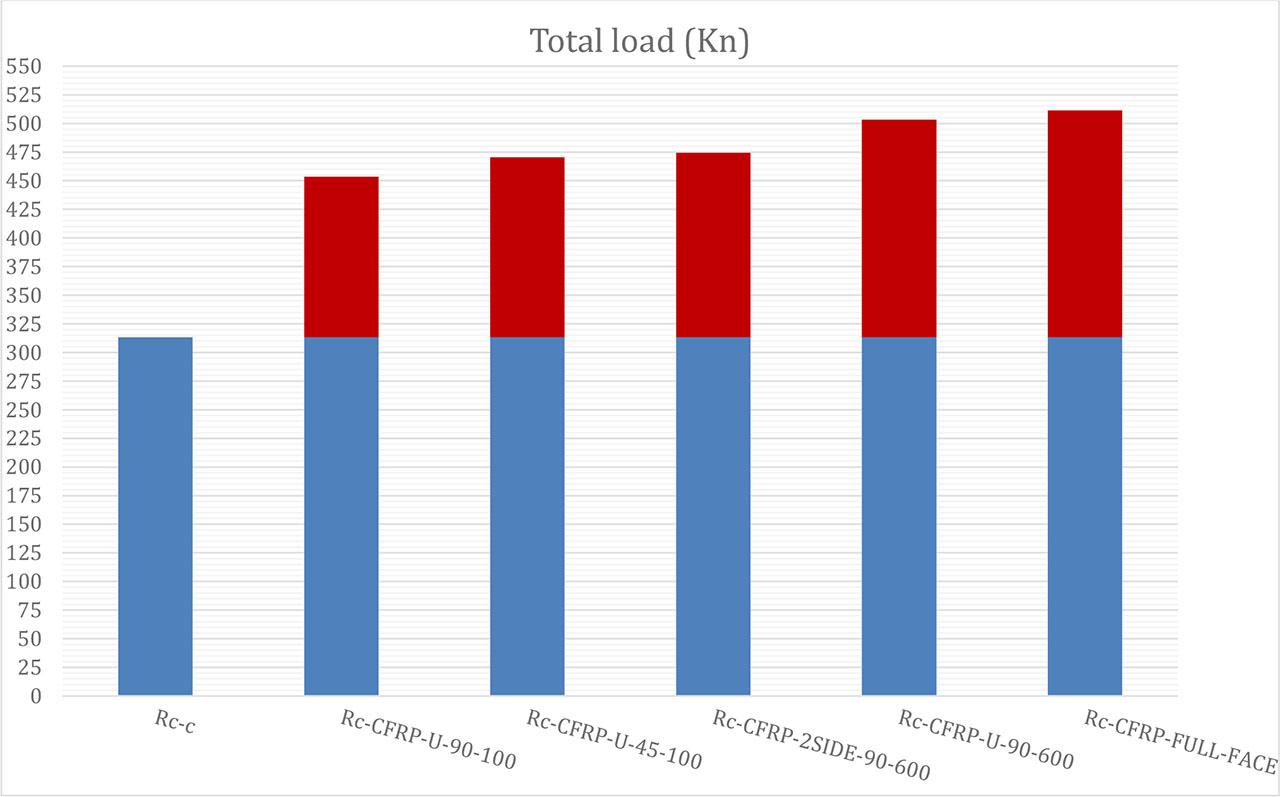
Total load (kN).
Vc (concrete shear contribution) was calculated based on ACI 318-19:
The ACI 318-19 code provides the following general expression for Vc, the contribution of concrete to sh strength for non-prestressed beams:
Where:
VC = nominal shear strength provided by concrete (in N or kN depending on units)
λ = modification factor for lightweight concrete (1.0 for normal weight)
fc′ = concrete compressive strength (MPa)
bw = width of the beam (mm)
d = effective depth of the beam (mm)
Vf (CFRP contribution) was calculated based on ACI 440.2R:
The CFRP contribution to shear strength is calculated as:
Where:
Vf = shear strength provided by the CFRP (N or kN)
Af = area of CFRP reinforcement crossing the shear crack (mm3)
ffe = effective stress in the CFRP at failure (MPa)
α = angle of the CFRP strip with respect to the longitudinal axis of the beam (typically 90° for vertical strips)
More detailed version (for U-wrap or side-bonded configurations):
Where:
tf = thickness of CFRP sheets (mm).
wf = width of single CFRP strip (mm)
Sf = spacing between CFRP strip (mm)
d = effective depth of the beam (mm)
ffe = effective stress in the CFRP at failure (MPa), limited to:
Where:
ɛfe= Effective strain (depends on failure mode; for deponding = 0.004–0.006).
Ef = modulus of elasticity of CFRP (mPa) strain.
The values extracted from the equations were adopted in the design of both concrete and CFRP. In the tables, the values resulting from the examination were included. For example, the control model was used (the total load applied to the model divided by 2) to represent the VC value. Therefore, it was used as a reference for the VC value. In the other specimens, the total applied load is divided by 2, equal to VT. By subtracting the VC value from the VT value, the result is VF, i.e., the carbon fiber contribution to each model can be known.
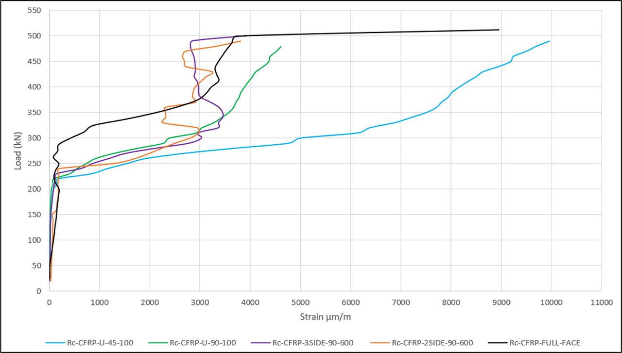
Figure 13 illustrate the comparative load-displacement behaviour of all tested specimens. The response of the UHPC beams can be categorized into three distinct stiffness phases: the elastic phase, where the material exhibits linear elastic behavior; the flexural phase, characterized by a reduction in stiffness due to the development of bending cracks; and the shear phase, where deformation is primarily governed by shear forces. All specimens displayed uniform elastic stiffness up to the initiation of the first flexural cracks, which occurred at an approximate load of 100 kN. During the flexural stiffness zone, the load-deflection response exhibited a linear trend, continuing until a diagonal fracture appeared on the surface of concrete in the load range of 100 to 350 kN. This is shown in Figure 13, which illustrates the peak load and mid-span deflection attained by the sample. At this stage, the applied force surged sharply, driven by the expansion of the diagonal shear crack. In the early loading phase, the reinforcement demonstrated similar stiffness across specimens, as the CFRP strengthening had little effect until the diagonal shear crack began to propagate. However, when peak stress was reached in the closed-shaped specimens, the shear cracking region was notably larger compared to that in the U-shaped specimens. The poor ability of the U-bending samples to withstand stress is linked to the CFRP bonding being shorter than desired for the test. Instead, specimens with the closed shape showed more deformation and a superior shear reinforcement system before failing. A detailed study of the load-deflection curve of such beams demonstrates the strong effect of CFRP reinforcement on their shear performance. Similar elastic and flexural stiffness was seen in each specimen, but where shear cracks appeared widely differed depending on the type of CFRP used. Despite being the original form, specimens with a U shape were more vulnerable to damage from CFRP bond shortness, but specimens with a closed shape performed better in plasticity and were more resistant to shear. Results suggest that the correct placement and length of CFRP reinforcement are important for higher shear strength and better durability. It is concluded that using carefully planned enhancement methods, for instance, the closed-shaped CFRP system, significantly increases the performance and stability of high-performance concrete structures for the long run.
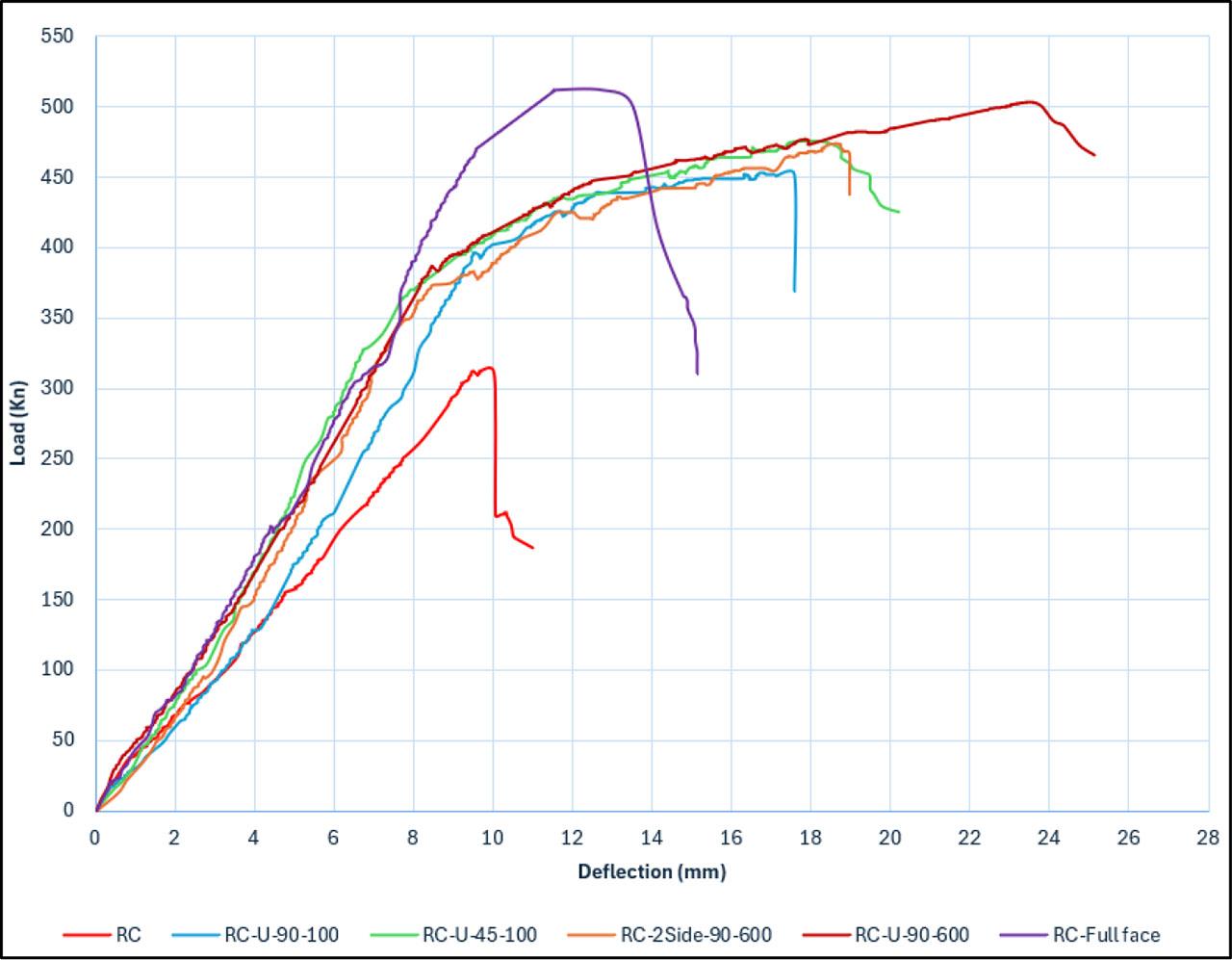
Load deflection charts.
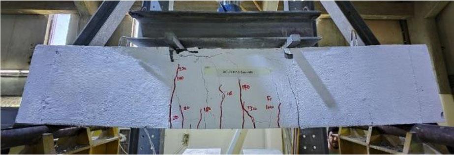
Table 14 lists the types of failures seen in the tested specimens and photographs of each of these are included in Figure 14-a to 14-f. Including CFRP reinforcement changed the shape and distribution of cracks on the beams. As a result of restricting cracks with CFRP, the width was lowered and the loss in friction was lessened. Because of this action, crack propagation was controlled throughout the loading process. But after the ultimate limit state was attained, the effect of crack-bridging disappeared instantly, causing the friction loss to quickly develop. Most of the stretching problems seen in the test were linked to how brittle the specimens became. Shear failure brought on by CFRP debonding was the main failure mode for the U-shaped samples. A debond was first found at the bond interface on a large region near the beam’s surface. The debonding took place at diagonal lines of failure shown in Figures 14-b and 14-c. When the load was increased, the debonding damage went on from the initial crack to involve both upper and lower regions of the beam. Higher fracture intensities and larger cracks in the treated specimens compared to controls showed that CFRP debonding greatly affects the strength of the structure. The specimens reinforced with closed-shaped CFRP failed differently, with rupture of the CFRP on both sides of the beam seen in Figures 14-d and 14-e. The diagonal cracks in the medium caused the fibres in the CFRP to tear as the strain in the material mounted. The results indicated greater improvement in shear strength when the CFRP broke than when it came off the concrete. The improved performance is mostly thanks to the longer effective bond length offered by its closed-formed construction. Many of the samples showed diagonal shear fractures, clearly highlighting that closed-shaped CFRP can take more shear loads.
Through their failure, the experimental beams demonstrated that CFRP reinforcement changes the manner in which UHPC fractures. Most of the U-shaped reinforcement samples broke because of CFRP debonding, but the closed type had a better shear strength, as their failure was caused by CFRP breaking rather than separation. This variation shows the great influence of reinforcing configuration on the strength of UHPC beams. The tests confirm that the closed-shaped CFRP reinforcement, with its extended length of bond, makes the structure better able to resist shear stress and limits fractures, leading to higher strength. The outcomes indicate that better CFRP reinforcement design—focused on adjusting bond length and form - can greatly increase the durability and overall performance of concrete structures facing shear forces, sharing useful information for future improvement in high-performance concrete design.
Failure modes.
| Sample | CFRP orientation | Vc (kN) | Vf (kN) | First shear crack Vcr (kN)) | Percentage gain in shear capacity | Type of failure |
|---|---|---|---|---|---|---|
| RC-C | 0 | 156.615 | 0 | 127 | 0 | Pure shear |
| RC-U-90-100 | 90° | 156.615 | 70.11 | 128 | 44.77% | Depending – shear- flexure |
| RC-U-45-100 | 45° | 156.615 | 78.630 | 127 | 50.21% | Pure Flexure |
| RC-2side-90-600 | 90° | 156.615 | 80.615 | 132 | 51.47% | Depending –pure flexure |
| RC-U-90-600 | 90° | 156.615 | 95.095 | 130 | 60.72% | Depending – flexure - shear |
| RC-Full-Face | 90° | 156.615 | 99.120 | / | 63.29% | Depending – pure shear |
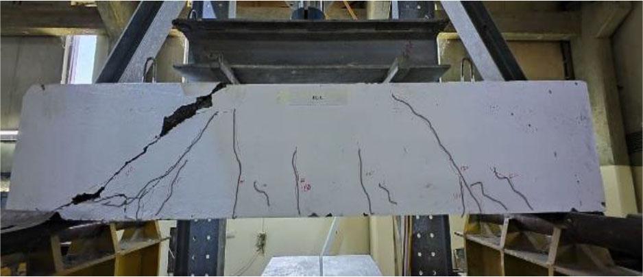
(RC).
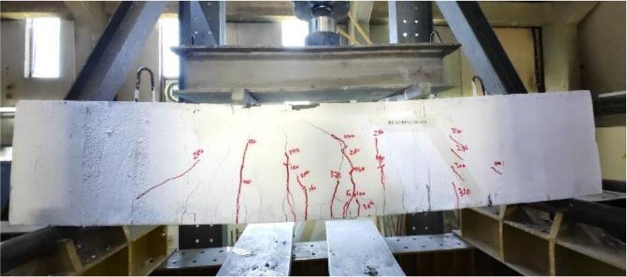
(RC-CFRP-U-90-100).
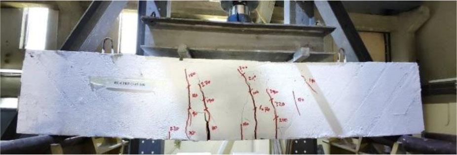
(RC-CFRP-U-45-100).
(RC-CFRP-2SIDE-90-600).
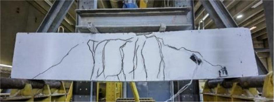
(RC-CFRP-U-90-600).
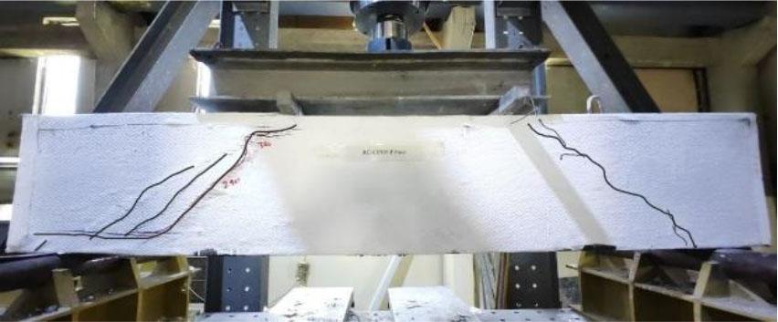
(RC-CFRP-FULL FACE).
The assessment of shear beam deformation depends on accurate measurements of strain to determine its structural characteristics. The strain analysis of this section evaluates the main steel bars together with the CFRP strips (sheets) that were used in the tested beam specimens. The strain evaluation contains thorough comparisons arranged per beam configuration in Table 15. The study shows how various reinforcement systems operate under load conditions.
Strain response of tested beams.
| Name of beam | Main steel strain [με] | CFRP strain (vertical strain) (με) | CFRP strain (diagonal strain) (με) |
|---|---|---|---|
| RC | 4120 | / | / |
| RC-CFRP-U-90-100 | 3214 | 8439 | 4618 |
| RC-CFRP-U-45-100 | 3157 | 9954 | 9954 |
| RC-CFRP-2SIDE-90-600 | 7211 | 5609 | 3812 |
| RC-CFRP-U-90-600 | 7398 | 6235 | 3920 |
| RC-CFRP-FULL FACE | 6382 | 14700 | 8954 |
The strain response of longitudinal steel reinforcement in UHPC beams follows a progressive pattern influenced by crack formation and loading conditions. During the initial loading phase, the longitudinal steel strain remains minimal, contributing insignificantly to the structural response. However, as flexural or shear cracks emerge, the steel reinforcement begins to elongate, engaging in load resistance and stress redistribution. A critical observation in the control sample was the absence of yielding in the central steel bar due to early shear failure, preventing full utilization of its tensile capacity. In contrast, reinforced specimens demonstrated greater strain development with increasing load, suggesting an enhanced load-sharing mechanism between CFRP reinforcement and longitudinal steel. Furthermore, comparable elongations were noted on both sides of the UHPC beams at lower loading levels, indicating a symmetrical stress distribution across the reinforcement system.
The steel strain curve, as presented in Figure 15, illustrates this gradual transition from elastic behaviour to plastic deformation in reinforced specimens. The experimental findings underscore the pivotal role of longitudinal steel reinforcement in the structural behaviours of CFRP-strengthened UHPC beams. While the control sample exhibited premature shear failure, the reinforced beams demonstrated improved strain capacity and load distribution, emphasizing the synergistic effect of CFRP and steel reinforcement. These findings highlight the necessity of optimizing reinforcement configurations to enhance strain compatibility, mitigate premature failure, and improve overall structural resilience. Future research should explore advanced analytical modelling and experimental validation to refine design guidelines, ensuring effective integration of CFRP and longitudinal steel reinforcement in high-performance concrete structures.
The strain response of CFRP reinforcement during loading follows a distinct two-phase pattern. In the initial phase, CFRP strains remain negligible, contributing little to the structural response. However, in the second phase, as loading increases, CFRP stresses escalate sharply, particularly beyond 100 kN, when the formation of initial cracks leads to diagonal shear fractures, potentially culminating in sample failure. At this early stage, the CFRP reinforcement provides minimal contribution to the overall shear capacity of the beam and can be considered insignificant. As the loading progresses, shear cracks propagate and widen, inducing higher CFRP stresses because of the CFRP strips’ ability to bridge cracks.
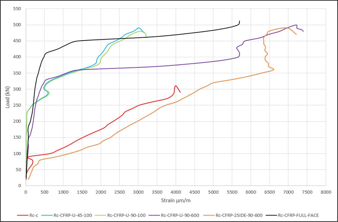
Load-strain curves.
This phenomenon is evident in Figure 16, which illustrates the vertical CFRP strain distribution at ultimate failure loads. A significant difference in strain behaviour was observed between U-shaped and closed-shaped CFRP reinforcement systems. The U-shaped system exhibited premature failure, leading to lower strain tolerance, while closed-shaped CFRP configurations demonstrated superior strain resistance, thereby enhancing structural resilience. The intricate stress patterns inside reinforced concrete beams affect the bond between the CFRP and concrete, which can lead to quicker CFRP debonding and lower the maximum strain the interface can withstand before failure. This underscores the importance of adequate CFRP anchorage and effective bond length in improving shear performance. The diagonal CFRP strains measured across all reinforced samples at failure are presented in Figure 17, reinforcing the critical role of CFRP configuration in governing shear behaviour and structural integrity. The study highlights the critical influence of CFRP reinforcement configuration on the strain response and shear performance of UHPC beams. Closed-shaped CFRP systems offer superior strain capacity and crack resistance, whereas U-shaped systems exhibit premature debonding and reduced effectiveness. These findings underscore the need for improved design strategies to optimize CFRP reinforcement, particularly in enhancing bond strength and anchorage efficiency. Future research should focus on refining analytical models to incorporate strain distribution, crack propagation mechanics, and CFRP bond behaviour, ensuring more accurate predictions and enhanced structural performance in CFRP-reinforced concrete systems. Figures 18, 19 and 20 show the maximum value of strains depending on the type.
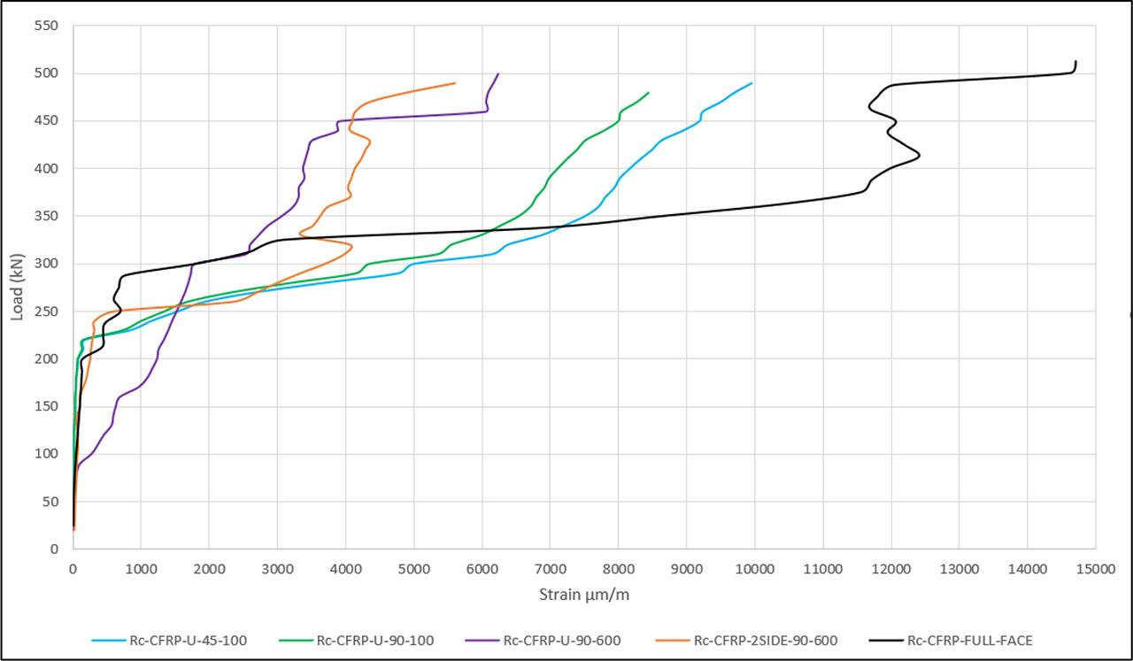
Load-vertical strain curves.
Load-diagonal strain curves.
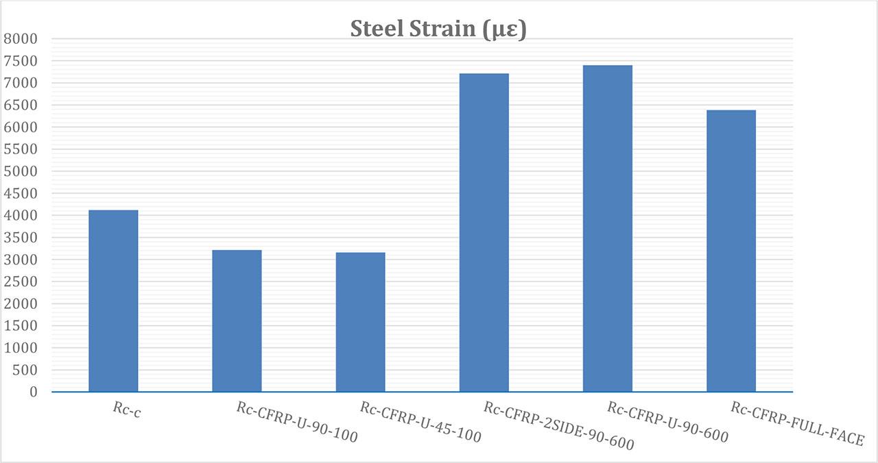
Maximum main steel strain for all beams.
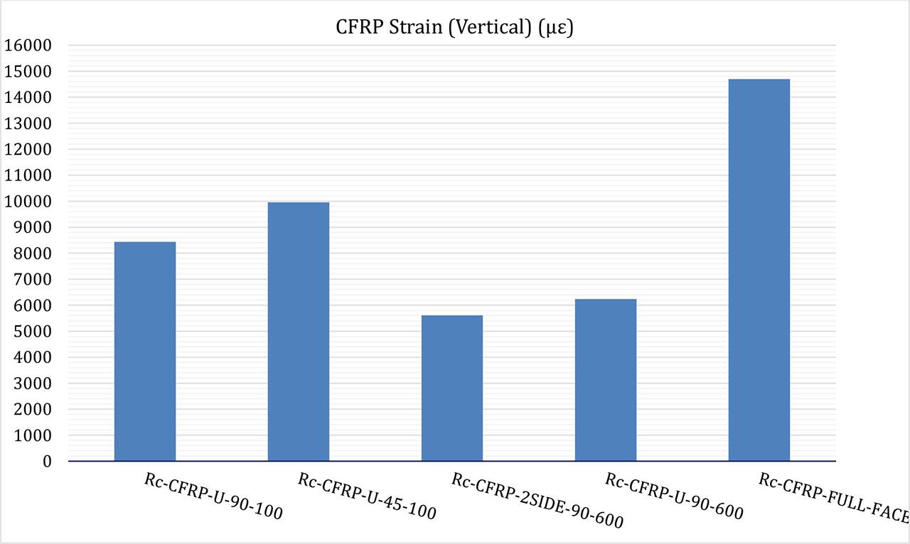
Maximum vertical CFRP strain for all beams.
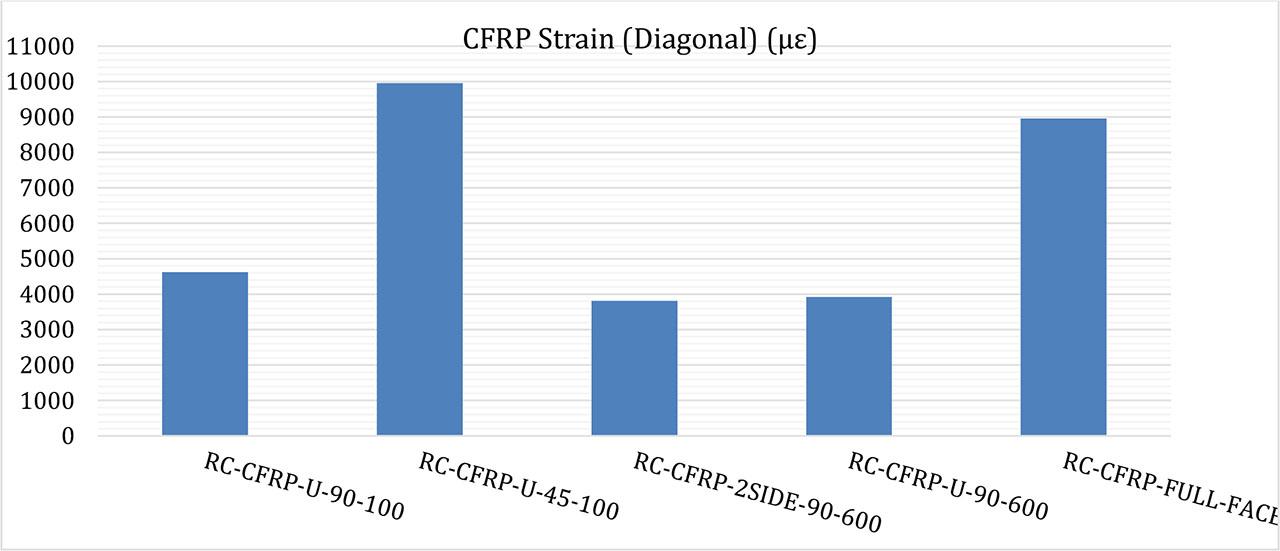
Maximum diagonal CFRP strain for all beams.
Existing structural design standards and guidelines, such as ACI 318-19, ACI 440.2R-17, TR-55, and CNR-DT-215-2018, serve as the primary references for structural engineering practices and provide methodologies for predicting the shear capacity of reinforced concrete beams, especially those strengthened with CFRP reinforcement. The outcomes of ACI 440.2R-17, TR-55, and CNR-DT-215-2018 enable the independent evaluation of CFRP's contribution to shear resistance, distinguishing it from that of the concrete matrix. To assess the reliability of these design codes in predicting CFRP reinforcement effects in UHPC beams, the experimental results obtained through the subtraction analysis method (presented in Table 15) were compared with numerical predictions derived from the existing design standards. The consolidated findings are reported in Table 16. The comparison indicates that TR-55, and CNR-DT-215-2018 tend to accuracy the shear contribution of CFRP in U-shaped full-face reinforcement configurations while ACI 440.2R-17 tends to overestimate the shear contribution of CFRP in U-shaped full-face reinforcement configurations. This overestimation primarily arises from the way these codes incorporate concrete compressive strength into their predictive models for CFRP effectiveness. Yet, this approach fails to fully describe the relationship between CFRP and concrete in UHPC beams, since the efficiency of CFRP is affected by the bond length and how strong the concrete substrate is. When results from experiments are contrasted with existing design codes, it becomes obvious that better models are needed to predict the shear strength of carbon fibre-reinforced cement beams. Experiments show that the ACI 318-19 code gives the most correct results. The findings point out that considering effective CFRP bond length and variations in concrete’s tensile strength greatly improves the accuracy of design calculations. Future studies should upgrade shear prediction models to pay attention to such important factors, resulting in safer and more economical layouts for CFRP-strengthened UHPC structures.
Observed vs. estimated shear contributions of CFRP in the strengthened specimens.
| Specimens | CFRP contribution determined by the subtraction approach: [kN] | CFRP contribution according to ACI 440.2R-17: [kN] | CFRP contribution according to CNR-DT-215- 2018: [kN] | CFRP contribution according to TR-55 (CS, 2013): [kN] |
|---|---|---|---|---|
| RC-U-90-100 | 70.110 | 73.132 | 62.218 | 47.695 |
| RC-U-45-100 | 80.615 | 103.698 | 93.327 | 67.250 |
| RC-2side-90-600 | 80.900 | 109.698 | 93.327 | 95.390 |
| RC-U-90-600 | 95.090 | 109.698 | 93.327 | 95.390 |
| RC-Full-Face | 99.120 | 109.698 | 93.327 | 95.390 |
This research included a detailed study of how UHPC beams reinforced by CFRP behave under shear, considering different ways in which the materials are arranged and located in the beams. Through experimental and numerical studies, we discovered important results about the effectiveness of CFRP reinforcement that can now inform structural design codes. Whenever closed-shaped CFRPs were used in beams, they showed a much higher strain capacity than U-shaped configurations, where CFRP came loose at the interface and reduced the beam’s shear capacity greatly. In comparison, the closed configuration of CFRP resulted in much better closure and high shear resistance.
Predictions relying on codes tended to overstate the shear contribution of CFRP, mainly when the section formed a U-shaped bracket. The main reason for the discrepancy is the short bond length between CFRP and UHPC surface, affected by the concrete tensile strength, which is not considered enough by the current models, leading to less accurate shear predictions for UHPC beams. The results prove that making changes to current design standards is necessary to support CFRP-strengthened UHPC beams in practice. Most of the present codes were developed using typical concrete data, making them suitable for few UHPC usage cases.
Additional analysis and research on the bond mechanisms within FRP and UHP concrete are needed to increase how reliable and efficient such reinforcement is. This research highlights the role of correctly characterizing CFRP when used in U-shaped reinforcement, as debonding can make performance unstable. Adjusting design techniques to look at bond length, tension in concrete and CFRP bolts will result in better predictions for shear capacities and failure types in UHPC concrete supported by CFRP. Stronger and more reliable use of CFRP in concrete building will be made safer with increased research.