

Concrete-filled steel tube (CFST) structures have become increasingly popular in modern construction due to the synergistic benefits of combining steel and concrete. The composite action enhances structural capacity, ductility, and fire resistance, making CFST members highly suitable for applications in high-rise buildings, bridges, and industrial facilities [1], [2]. The steel tube provides confinement to the concrete, improving its compressive strength, while the concrete core supports the steel tube against inward buckling, leading to overall enhanced structural performance [3].
Despite their advantages, CFST members are often subjected to initial imperfections arising from fabrication errors, handling damage, environmental exposure, or service-related deterioration. Imperfections such as notches, corrosion pits, or residual stresses can significantly affect the mechanical behaviour of CFST members under flexural loading [4], [5]. Notches are particularly critical, as they introduce stress concentrations that can precipitate local buckling, premature yielding, and potentially catastrophic failure modes [6].
Although numerous investigations have been conducted on the response of complete CFST units under axial, flexural, and cyclic imposed loading conditions [7], [8], comparatively little has been done on the effects of initial imperfections, particularly local notches. Xie et al. [9] experimentally demonstrated that localised dents and notches can significantly reduce the flexural stiffness and load capacity of CFST beams. Similarly, Yu and Zhou [10] showed that even minor imperfections can substantially influence the ultimate flexural performance. Further effects of notch depth and location in square CFST beams were studied by Zhang et al. [11], who reported that deeper notches, especially at the mid-span region, resulted in considerable reductions in moment capacity.
In a relevant experimental investigation, Han et al. [12] demonstrated the influence of geometric imperfections on the behaviour of CFST members under various loading scenarios, reinforcing the need for more focused studies on initial localised flaws such as notches.
To address this gap, the present study adopts an experimental approach. Four-point bending tests are conducted on CFST specimens with controlled notch parameters to investigate their flexural behaviour, including bending strength, stiffness degradation, and failure modes.
The primary objectives of this research are:
- 1)
Experimentally investigate the influence of various notch geometries on the flexural performance of concrete-filled steel tube (CFST) members.
- 2)
Quantify the flexural strength and stiffness reduction resulting from different notch configurations in CFST beams.
- 3)
Analyse and classify the failure modes of notched CFST specimens under monotonic bending to inform safer and more effective structural design practices.
The remainder of this paper is organised as follows: Section 2 provides a comprehensive literature review; Section 3 details the experimental methodology; Section 4 discusses the results and analysis; and Section 5 concludes with key findings and recommendations for future work.
Some experimental tests have determined the flexural capacity and failure modes of CFST beams. The flexure behaviour has been shown by Li et al. [13] and Zhang et al. [14] to be significantly affected by the interaction between the concrete core and the steel tube, where the local buckling and yielding dominate as failure mechanisms. The composite action of the subject plates delays the onset of local buckling with increased moment capacity compared to unfilled steel tubes [15]. Additionally, additional studies have demonstrated that the concrete-to-steel bond enhances stiffness and ductility against bending loads [16]. Deep research findings also show that the quality of the concrete mix and thickness of steel tube significantly influence the whole performance, with thicker tubes having higher moment capacity and stable failure modes [17]. These results emphasise the need to optimally design material properties and parameters to exploit the composite character of the CFST constituents. Notches and other imperfections in CFST sections radically change loading, resulting in stress concentration that reduces flexural capacity. In turn, Kumar et al. [18] demonstrated that notches cause local failures at lower loads, and notch geometry – its depth, width and location contribute to ductility and energy absorption reduction [19]. Other works confirm that these imperfections lead to non-homogeneous stress fields and localised buckling, undermining the structure’s integrity [20]. To alleviate such effects, upgraded manufacturing methods and reinforcement techniques (local strengthening and high-performance concrete mixtures) have been suggested [21].
Despite numerous studies examining the general behaviour of CFST members, there remains a significant gap in theoretical and experimental research specifically addressing notched CFST members. Limited attention has been given to understanding how different notch geometries affect flexural performance parameters such as moment capacity, stiffness, and ductility. This lack of comprehensive experimental data restricts the development of reliable theoretical frameworks for localised damage in design calculations. Although recent experimental efforts by Li and Chen [22], Huang et al. [23], and Al-Shaar [24] have begun to explore this topic, further in-depth investigations are required to establish generalised theoretical insights applicable in engineering practice. Other notable contributions to the broader field of CFST flexural behaviour include studies by Abolghasem et al. [25], Basuki and Lee [26], Zhou et al. [27], Zhao and Li [28], Feng et al. [29], Kim et al. [30], Park and Lee [31], Gupta et al. [32], Chang et al. [33], Sadiq and Hussain [34], Youssef et al. [35], Li et al. [36], Wei and Yang [37], Rahman et al. [38], and Najim et al. [39]. Reviews by Fardis [40] and others [41], [42], and [43] further highlight the need for focused studies on structural defects. This review underscores the importance of a targeted theoretical and experimental investigation into the flexural behaviour of notched CFST members, forming the current study’s foundation.
An experimental investigation was conducted to examine the structural performance of Concrete-Filled Steel Tube (CFST) beam members, focusing on the influence of artificial notches representing initial cracking. The primary objective was to assess the effect of such defects on the flexural behaviour of the CFST beam member in comparison to control specimens.
Twelve specimens were fabricated and tested under monotonic loading conditions to evaluate the flexural behaviour of concrete-filled steel tube (CFST) beam members with and without initial imperfections. The specimen set comprised two control specimens (Control-2.7 and Control-4.7), defect-free CFST beam members constructed with steel wall thicknesses of 2.7 mm and 4.7 mm, respectively. Additionally, two hollow steel tube specimens (Hollow-2.7 and Hollow-4.7) were tested as benchmarks to assess the structural contribution of the concrete infill. The remaining eight specimens were defective CFST beams, each incorporating an artificial notch measuring 8 mm × 80 mm to simulate initial cracking. These notched specimens were categorised according to the steel wall thickness (either 2.7 mm or 4.7 mm) and the specific location and orientation of the notch, allowing for a comprehensive investigation into the influence of imperfection characteristics on structural performance. All specimens shared consistent cross-sectional dimensions of 150 mm × 150 mm and a uniform length of 1500 mm. The notches were introduced either in the upper compression zone or lower tension zone, with vertical or horizontal orientations.
The experimental evaluation included analysing the load-deflection curve, moment capacity, and failure mode to determine each specimen’s flexural performance under the applied loads.
Table [1] summarises the classification of the tested specimens, including their designation, wall thickness, notch location and orientation, and width-to-thickness ratio (B/t). The designation codes reflect both the position and direction of the notches: STV and STH represent specimens with vertical and horizontal notches, respectively, located in the compression zone (top), while SBV and SBH refer to vertical and horizontal notches positioned in the tension zone (bottom). Vertical notches are oriented parallel to the longitudinal axis of the beam, whereas Horizontal notches are perpendicular to it.
Sample details.
| Beam designation | Width (mm) | Length (mm) | Thickness (mm) | Location of notch | Direction | B/t |
|---|---|---|---|---|---|---|
| Control-2.7 | 150 | 1500 | 2.7 | - | - | 55.56 |
| Control- 4.7 | - | - | 4.7 | - | - | 31.9 |
| Hollow-2.7 | - | - | 2.7 | - | - | 55.56 |
| Hollow-4.7 | - | - | 4.7 | - | - | 31.9 |
| STV-2.7 | - | - | 2.7 | top | vertical | 55.56 |
| STV-4.7 | - | - | 4.7 | top | vertical | 31.9 |
| STH-2.7 | - | - | 2.7 | top | horizontal | 55.56 |
| STH-4.7 | - | - | 4.7 | top | horizontal | 31.9 |
| SBV-2.7 | - | - | 2.7 | bottom | vertical | 55.56 |
| SBV-4.7 | - | - | 4.7 | bottom | vertical | 31.9 |
| SBH-2.7 | - | - | 2.7 | bottom | horizontal | 55.56 |
| SBH-4.7 | - | - | 4.7 | bottom | horizontal | 31.9 |
All Concrete-Filled Steel Tube (CFST) specimens were prepared using cold-formed industrial steel tubes. The tubes were precisely cut to the required length using a high accuracy cutting machine to ensure consistent dimensions across all samples. After cutting, the edges of the tubes were meticulously smoothed and cleaned to eliminate any sharp burrs or surface contaminants that might affect specimen integrity.
All exposed steel surfaces were coated with rust-inhibitive paint to enhance corrosion resistance. Additionally, to ensure proper vertical alignment during the concrete casting process and to prevent concrete leakage from the bottom, a square steel plate larger than the tubes’ cross—sectional dimensions was securely welded to the base of each specimen.
Artificial notches were introduced to simulate initial defects for eight CFST specimens. These notches were precisely fabricated using a laser cutting machine to ensure uniformity and accuracy. Each notch measured 8 mm in width and 80 mm in length and was centrally positioned along the height of the specimen.
The notches were oriented vertically or horizontally, depending on the designated specimen configuration. Fig. 1 illustrates the different notch orientations applied to the samples.
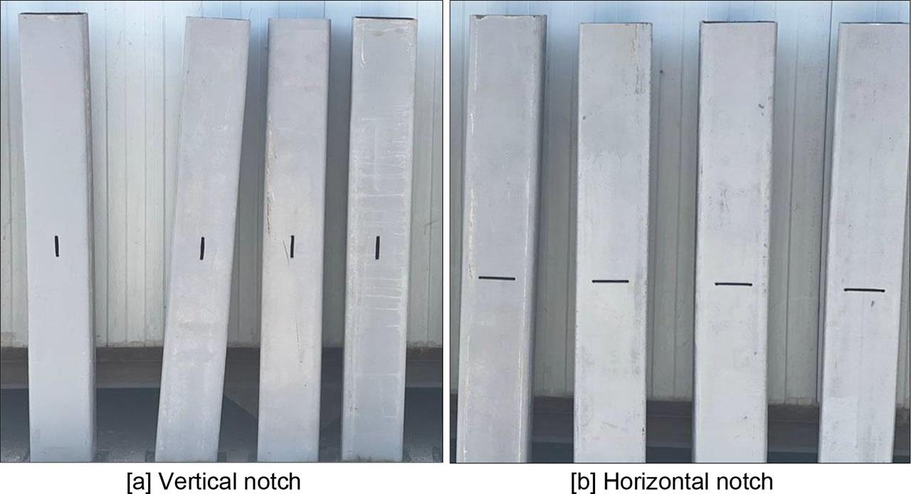
Vertically and Horizontally Oriented Notches.
Standard concrete is typically used as the infill, providing compressive strength and enhancing ductility. The steel tube confines the concrete, while the concrete supports the steel by improving its flexural resistance and delaying local deformations. However, defects in the steel, such as dents or corrosion, can disrupt this confinement, leading to stress concentrations, reduced load capacity, and altered performance under bending forces.
A typical concrete mix ensures consistency by standardising the concrete properties, allowing the study to focus on the effects of steel defects without introducing variability from the concrete itself. This simplifies isolating the impact of steel imperfections on flexural strength, crack propagation, and failure modes. It also highlights how defects in the steel affect the interaction between the steel tube and the concrete core, influencing the overall flexural behaviour of the CFST beams. The concrete mixes were designed to achieve a target compressive strength of 45 MPa. The concrete mix proportions are listed in Table 2.
Mix proportions.
| Components (kg/m3) | Water | W/C | ||
|---|---|---|---|---|
| Cement | Sand | Gravel | ||
| 395 | 730 | 980 | 185 | 0.47 |
The steel used for the CFST samples was imported from Turkey. Each batch of imported steel underwent quality control processes, including chemical and physical tests to verify the material’s properties. The properties of the steel tubes used in the CFST samples were taken from the original tubes with different thicknesses. These samples were then tested to examine the chemical and physical characteristics of the steel. The sampling, cutting, and testing procedures followed the DIN 50125 standard [44]. Fig. 2 shows the tested steel coupons along with the tensile testing machine. The stress-strain curve obtained from one of the tensile tests is illustrated in Fig. 3, which also includes a summary table presenting the detailed tensile properties of the tested samples.
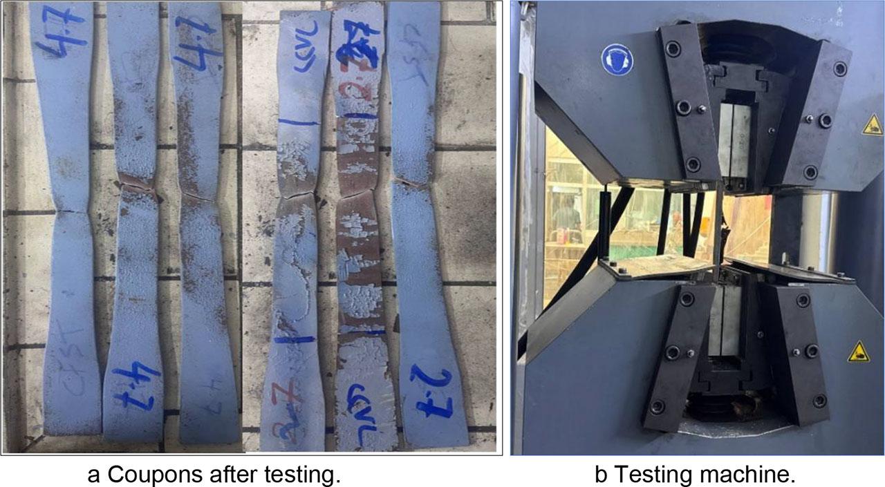
Tensile strength test of steel coupons.
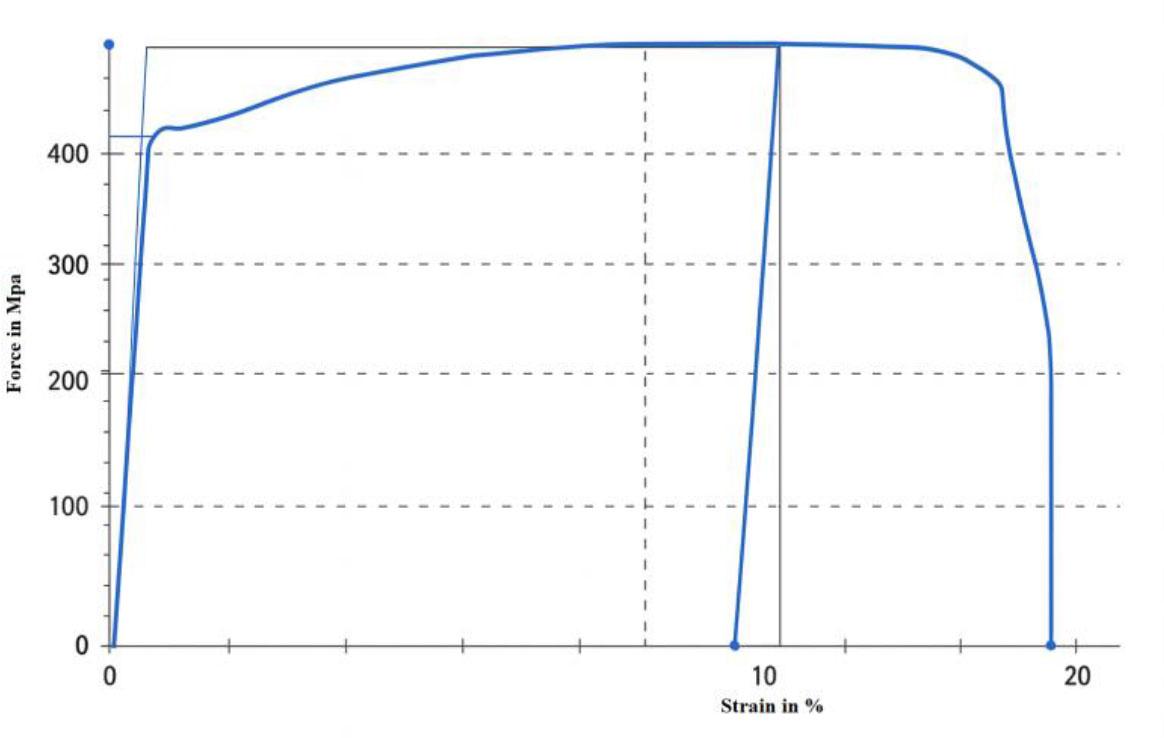
Stress-strain curve behaviour and tensile properties of steel tubes.
All samples were cast at the Age of Exploration Company in Dora, Baghdad. They were welded to the base plates to ensure central alignment of the steel tubes. Silicone glue was applied to fill the gaps between the weld points, and adhesive tape was placed at the notched site to prevent the leakage of cement mortar and water. Each specimen was labelled for identification.
The CFST samples were positioned on a flat wooden board to maintain stability during the concrete casting. Concrete was manually poured into the samples, and a vibrator was used to remove air bubbles and ensure uniform setting of the mixture. The average Results of mechanical properties are listed in Table 3.
Results of mechanical properties.
| Specimens | fcu(MPa) exp. | fc′(MPa) exp. | ft (MPa) | Ec (GPa) | fr (MPa) | |||
|---|---|---|---|---|---|---|---|---|
| Exp. | ASTM C496M-17 | Exp. | ASTM C469M-22 | Exp. | ASTM C78M-22 | |||
| Cubes | 42.1 | - | - | - | - | - | - | - |
| Cylinders | - | 34.1 | 3 | 3.1 | 30.4 | 27.4 | - | - |
| Prisms | - | - | - | - | - | - | 4.1 | 3.6 |
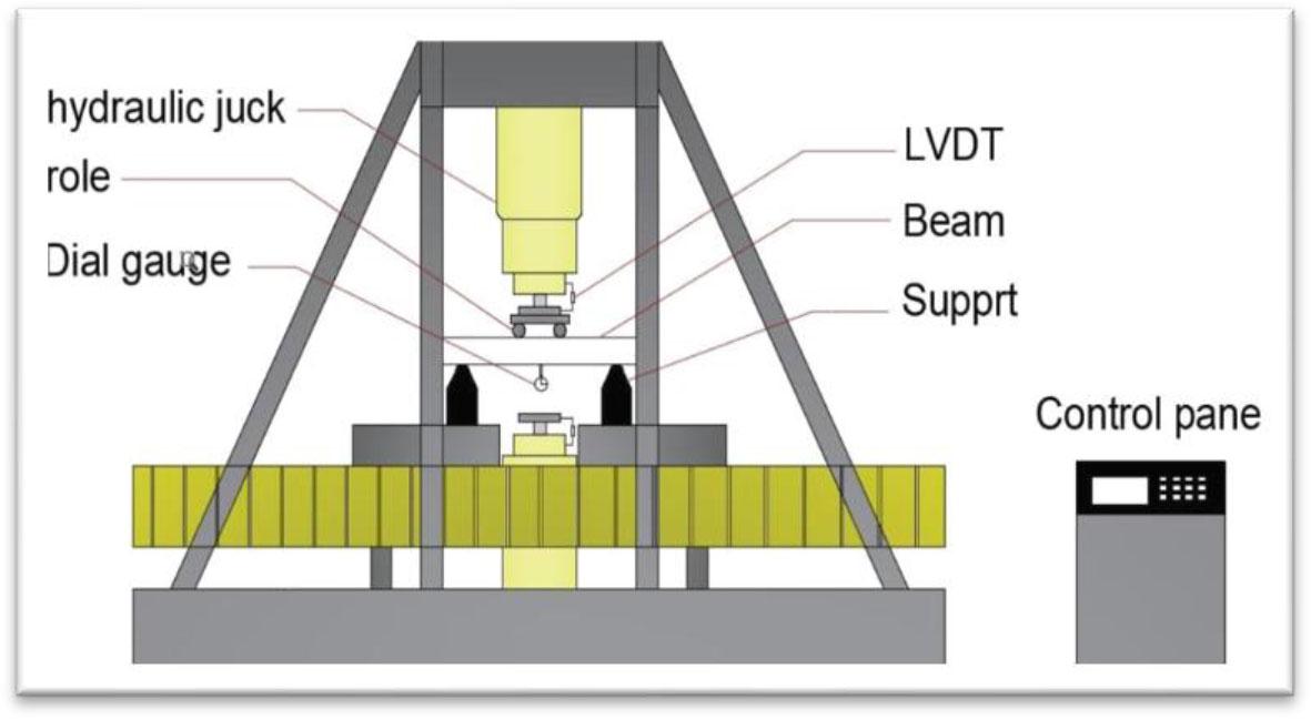
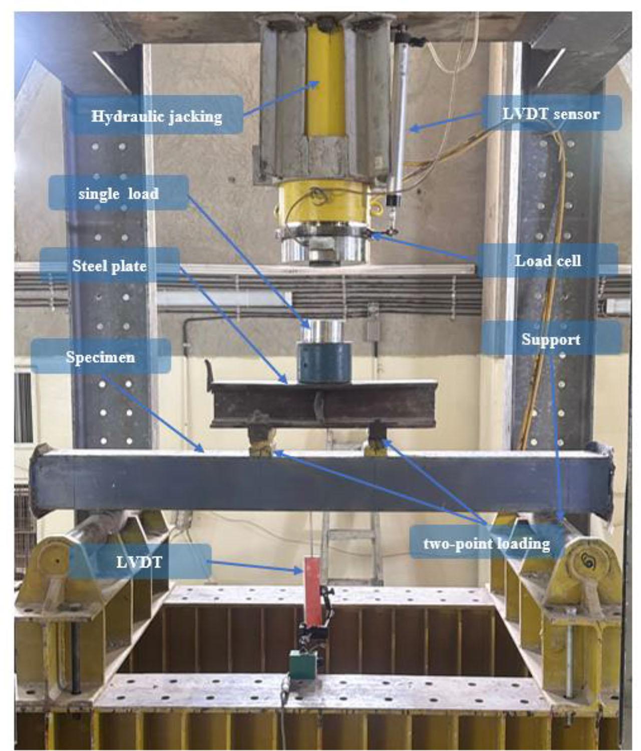
The experimental program was conducted at the Civil Engineering Laboratory of the College of Engineering, Al-Nahrain University. All CFST beam specimens were tested under monotonic loading using a hydraulic testing machine with a maximum capacity of 2000 kN, as illustrated in Figure 4. The test setup included a data acquisition system connected to a smart load cell and a data logger, which recorded load and deflection values at one-second intervals. The data were automatically stored in Excel format for further analysis.
A two-point loading system was adopted to simulate real-world flexural behaviour. The supports and load application points were carefully positioned and clearly labelled to ensure consistent and accurate load distribution. Initially, a single-point axial load was applied at the loading bridge’s top centre using the hydraulic jack. This load was distributed into two symmetrical point loads through a steel spreader beam connected to the test frame.
Fig. 4a, 4b show that each beam specimen was placed horizontally on two rigid steel supports. A steel plate was positioned between the hydraulic actuator and the specimen to ensure uniform load transfer. LVDT sensors were used to monitor deflection at midspan and other critical locations. This configuration allowed for an accurate assessment of the specimens’ structural response under controlled monotonic bending conditions.
Hydraulic testing machine.
Test setup for beam specimen.
Twelve beams’ results were analysed and discussed, focusing on load versus deflection, ultimate load, and failure modes. The beams were prepared for testing and subjected to a single-point load applied to the centre of the upper section of the load-bearing bridge, which was distributed as two-point loads across the bridge arms. The loading continued until no further loads were applied.
The effect of defects in the beams was compared to control tubes, showing that the concrete core within the steel tubes significantly enhanced the beams’ moment-carrying capacity while reducing deflection. This confirmed that the CFST beams exhibited a stronger load response. The size and location of cracks and their relationship to failure modes were examined and compared to control specimens to assess structural integrity and failure mechanisms. The results are as shown in Table 4.
Summary of the experimental results.
| Beam designation | Ultimate load pu (kN) | Ultimate Deflection du (mm) | % decrease in Ultimate Load | % Decrease in Ultimate Deflection |
|---|---|---|---|---|
| Hollow-2.7 | 45.3 | 9.5 | 72.71 | 77.38 |
| Hollow-4.7 | 154 | 16.3 | 49.84 | 71.40 |
| Control-2.7 | 166 | 42 | - | - |
| Control- 4.7 | 307 | 57 | - | - |
| STV-2.7 | 156 | 13 | 6.02 | 69.05 |
| STV-4.7 | 276 | 31 | 45.61 | 45.61 |
| STH-2.7 | 159 | 33 | 4.22 | 21.43 |
| STH-4.7 | 290 | 52 | 5.54 | 8.77 |
| SBV-2.7 | 153 | 13 | 7.83 | 69.05 |
| SBV-4.7 | 296 | 34 | 3.58 | 40.35 |
| SBH-2.7 | 116 | 10 | 30.12 | 76.19 |
| SBH-4.7 | 233 | 20 | 24.10 | 64.91 |
Fig. 5 illustrates the load capacities of all tested specimens. It is observed that notched beams, regardless of whether the notch orientation was vertical or horizontal, or whether located in the compression or tension zones, exhibited significant reductions in load capacity compared to their respective control specimens. For instance, the STV-2.7 (156 kN), SBV-2.7 (153 kN), and SBH-2.7 (116 kN) specimens all demonstrated lower load capacities than the Control-2.7 specimen, which reached 166 kN. These results highlight that even minor geometric imperfections introduce stress concentrations that markedly diminish the flexural strength of CFST members.
An increase in tube thickness positively influenced the structural performance. Specimens such as STV-4.7, SBV-4.7, and STH-4.7 attained load capacities of 276 kN, 296 kN, and 290 kN, respectively, outperforming their thinner 2.7 mm counterparts. Nonetheless, despite the beneficial effect of increased wall thickness, the adverse impact of notches remained evident, underscoring the inherent limitations of relying solely on thickness to offset the detrimental effects of initial defects.
Fig. 6 presents the ultimate deflection values recorded for all specimens. Contrary to typical expectations, the notched CFST specimens consistently exhibited lower deflections than their corresponding control specimens, suggesting a notable reduction in ductility due to localised damage caused by notches. The Control-4.7 beam displayed the highest ultimate deflection at approximately 57 mm, followed by STH-4.7 and SBV-4.7 with deflections around 52 mm and 34 mm, respectively. Conversely, STV-2.7 and SBH-2.7 showed significantly diminished deflections, with the lowest deflection observed in the Hollow-2.7 specimen (~9.5 mm), which inherently lacks a concrete core and thus demonstrates limited energy absorption capacity.
These findings emphasise the complex influence of notches on the flexural behaviour of CFST members, particularly regarding deformation capacity. A direct and detailed comparison between notched beams and their matched control specimens reveals a consistent pattern: notches substantially reduce deformation capacity, reflecting ductility and energy dissipation potential degradation. For example, although thicker steel tubes (4.7 mm) generally correlate with higher deflections, notched specimens like STV-4.7 and SBV-4.7 register noticeably lower ultimate deflections than the Control-4.7 specimen. This indicates that geometric imperfections impose localised stiffness and promote premature failure mechanisms that cannot be fully mitigated by increasing wall thickness.
In contrast, control specimens-free from initial defects-exhibit superior flexibility and enhanced deformation capacity under load, underscoring the essential role of structural integrity in preserving ductile behaviour. This contrast is particularly pronounced when considering the ultimate deflections: Control-2.7 (42 mm) and Control-4.7 (57 mm) significantly outperform their notched counterparts, despite the latter having increased thickness in some cases. This disparity further confirms that increasing thickness alone is insufficient to compensate for the detrimental effects introduced by notches.
Moreover, while hollow specimens inherently display minimal deformation due to the absence of a concrete core, the critical comparative analysis lies between filled notched beams and their pristine controls. Here, the detrimental influence of notches becomes unmistakably evident through reduced deflection capacities. These observations strongly advocate for stringent control and minimisation of initial imperfections during manufacturing and design processes to maintain the intrinsic ductility and energy absorption capacity characteristic of CFST members.
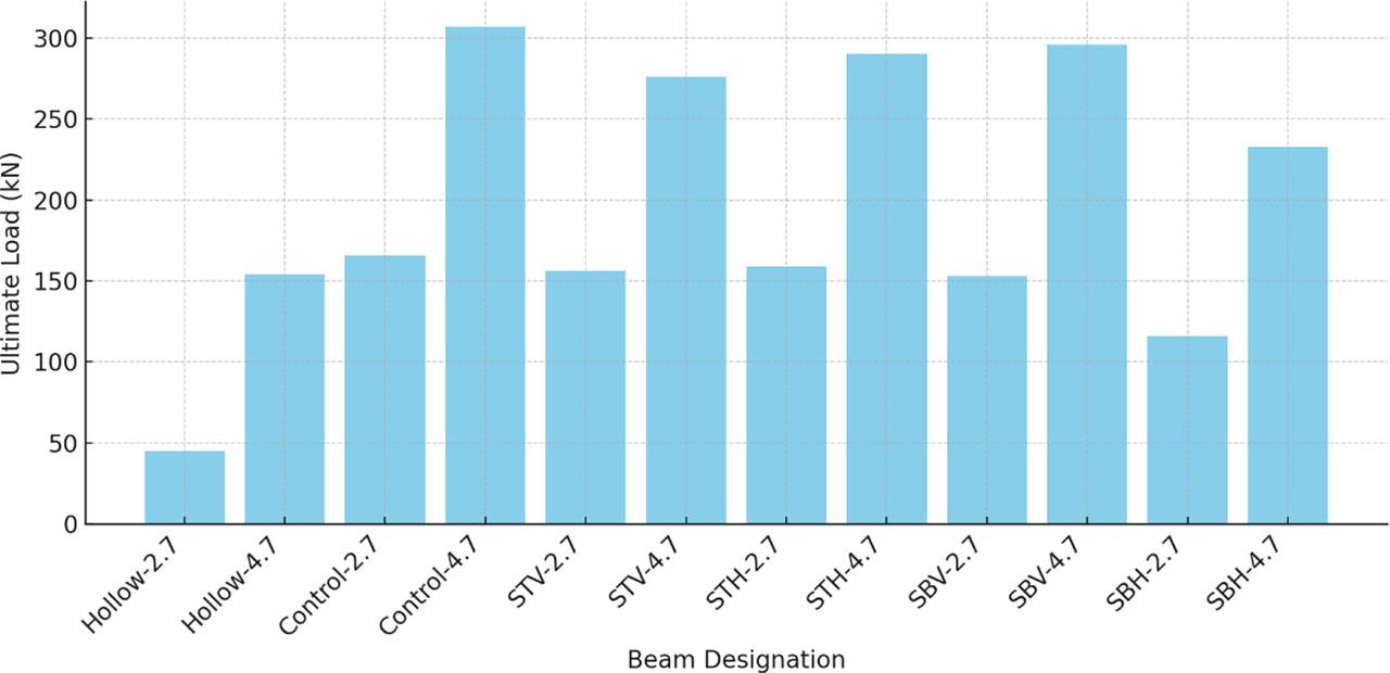
Ultimate load.
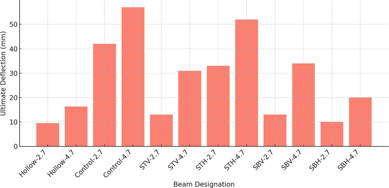
Ultimate deflection at ultimate load.
A square cross-section of 150 × 150 mm was tested under monotonic four-point bending. The specimens differed only in wall thickness: one with 2.7 mm and the other with 4.7 mm steel thickness. These control samples were intended to establish baseline structural behaviour and to serve as a reference for evaluating the performance of defective and concrete-filled counterparts.
As illustrated in Fig. 7, the specimen with 4.7 mm thickness exhibited notably higher bending resistance due to its greater yield strength and enhanced cross-sectional stiffness, resulting in a more stable deformation pattern. In contrast, the 2.7 mm specimen showed larger lateral deformations and was more susceptible to local instability and premature yielding, especially in the compression zone. Both specimens primarily failed due to flexural bending, characterised by gradual deformation followed by local buckling near the maximum moment region.
The inclusion of concrete infill in subsequent CFST specimens significantly improved structural performance. It enhanced composite action between the steel tube and concrete core, reduced the risk of local buckling, and provided better load distribution, particularly in the thinner 2.7 mm tubes.
All tested beams-regardless of thickness-displayed a typical moment-deflection response, beginning with a linear elastic phase, followed by a gradual reduction in stiffness leading up to peak bending capacity. Post-yield behaviour was more stable and ductile in the 4.7 mm specimen, confirming that increased tube thickness contributes to greater structural resilience, energy dissipation, and failure resistance under monotonic bending loads.
These observations underscore the critical role of steel tube thickness in governing the overall flexural behaviour of CFST members, especially when evaluating the effects of initial defects or notches in practical applications.
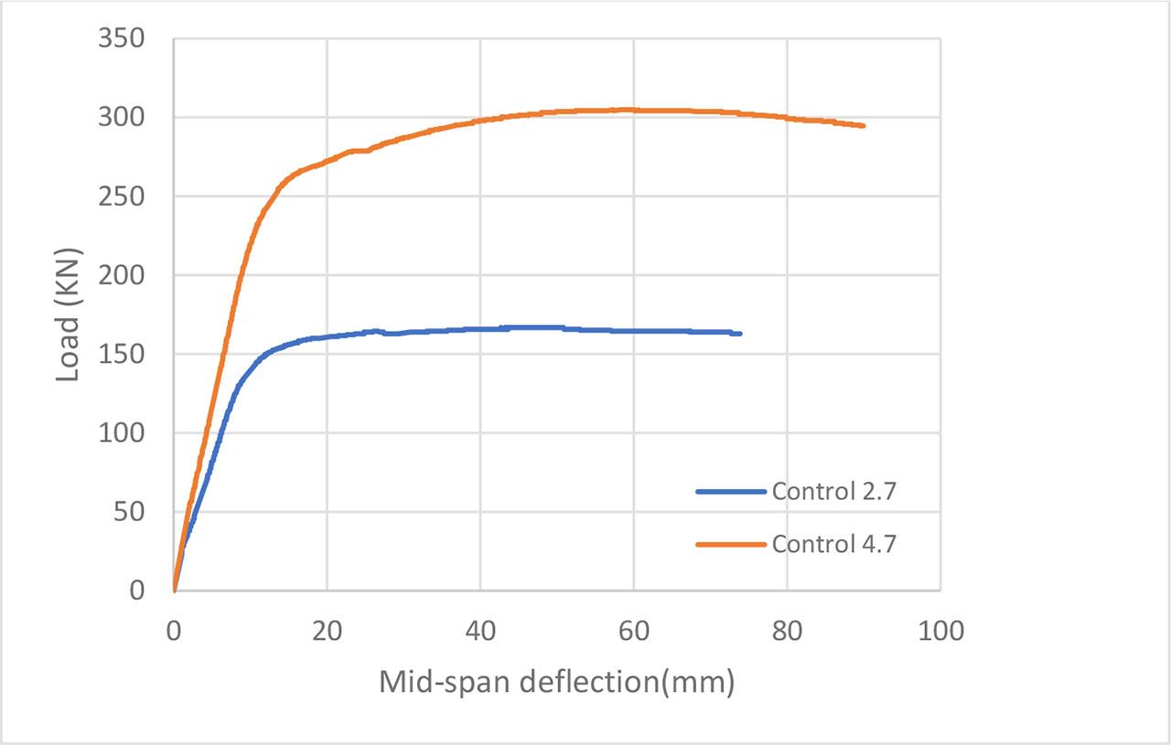
Load deflection curves of control beams.
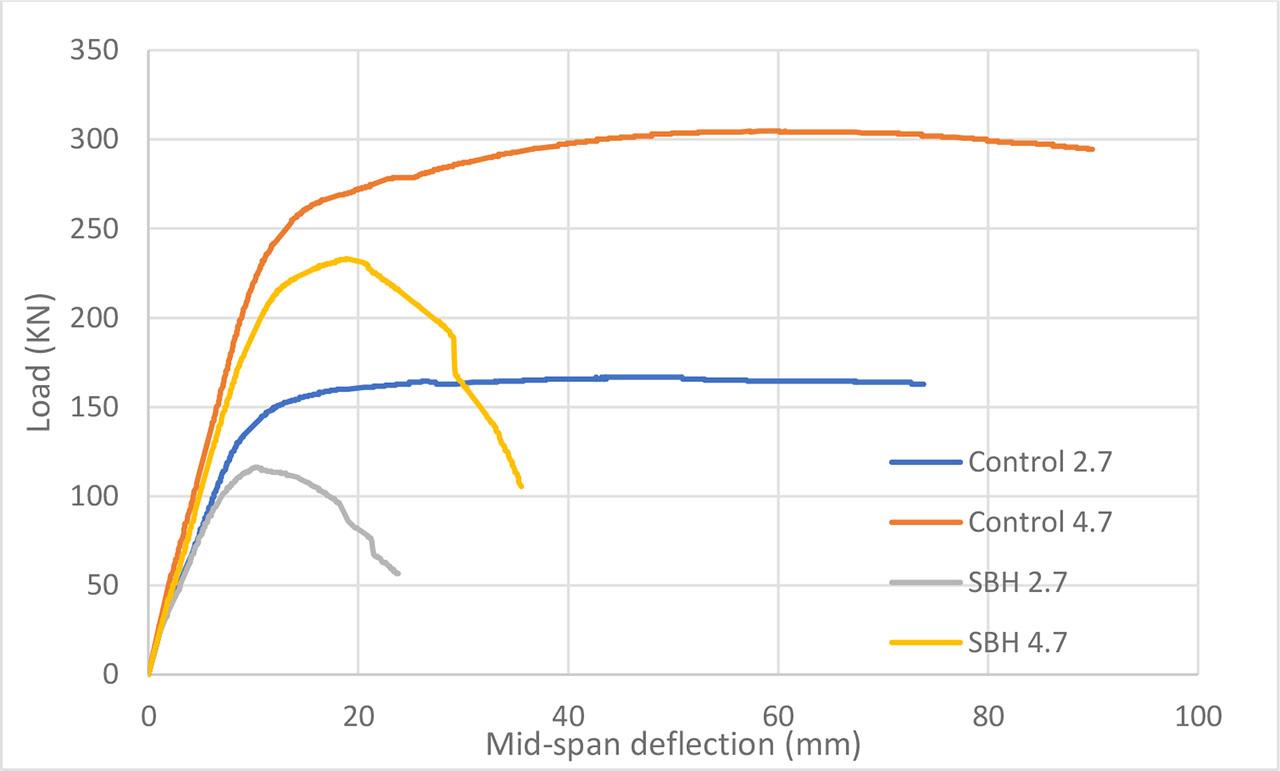
Fig. 8 shows that the load-displacement behaviour reveals significant differences between the concrete-filled steel tube (CFST) specimens and hollow steel tube specimens under bending loads. The 4.7 mm-thick CFST specimen exhibited the highest flexural strength, demonstrating excellent elasticity and ductility. This enhanced performance underscores the critical role of concrete infill in improving the flexural behaviour of steel tubes, as the infill significantly contributes to better stress distribution and increased stiffness.
While slightly weaker than its 4.7 mm counterpart, the 2.7 mm-thick CFST specimen outperformed the hollow steel tubes. This highlights the importance of concrete infill in increasing flexural strength, even when the steel thickness is reduced. In contrast, regardless of their thickness, the hollow steel tube specimens showed much poorer performance, with premature failure and lower load-bearing capacity. These results underline the limitations of hollow sections under bending loads.
Concrete infill improves flexural strength, enhances energy absorption, delays local buckling, and provides better structural stability. Therefore, concrete infill is an effective method for improving the performance of steel tubes under bending loads, offering a significant advantage over hollow tubes.
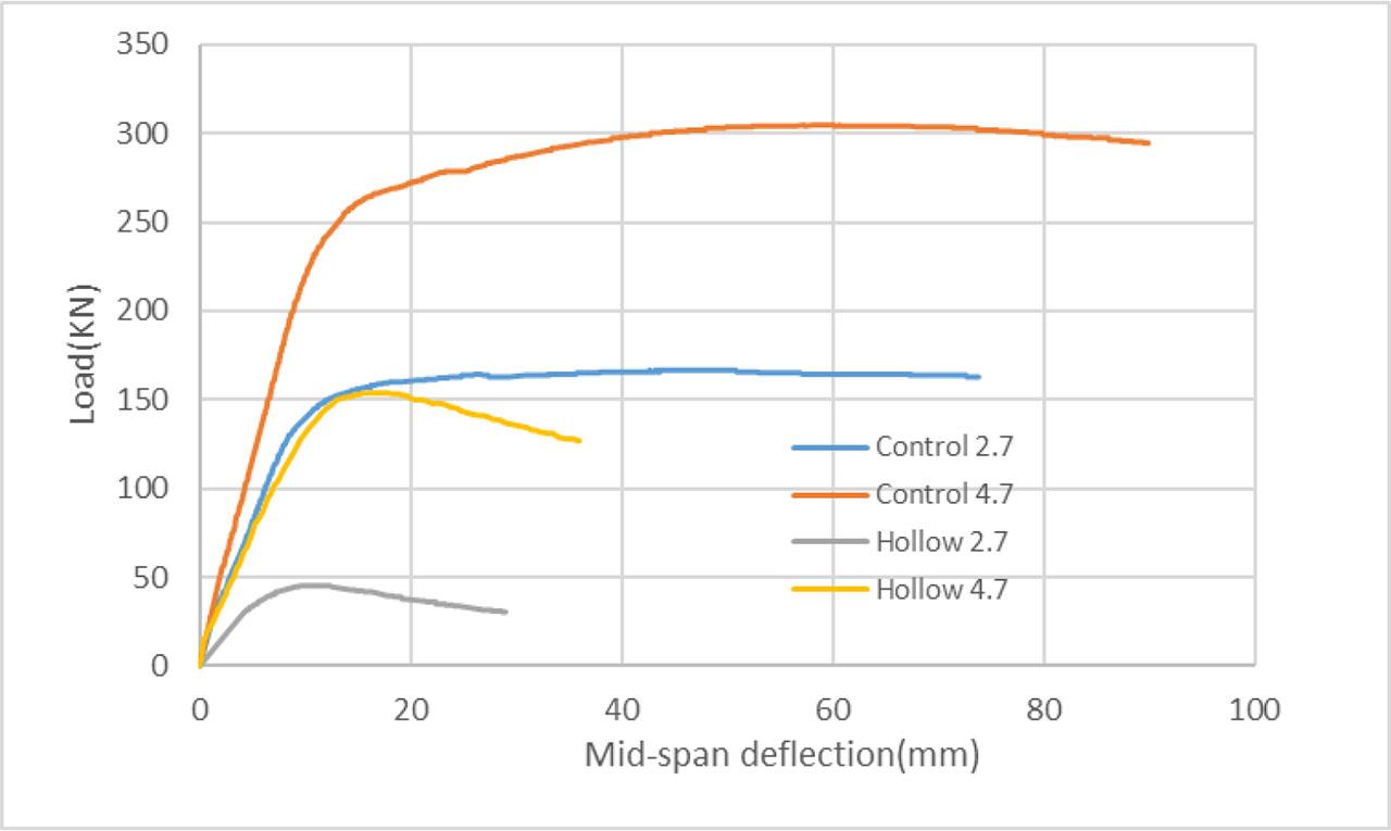
Load-deflection curves for control specimens compared to hollow specimens.
As illustrated in Fig. 9, the specimens designated STV 2.7 mm and STV 4.7 mm, incorporating identical vertical notches in the compression zone, exhibited noticeably different flexural behaviours under monotonic loading. The uniform notch geometry across both specimens enables a direct comparison of the influence of steel wall thickness on structural performance.
Surprisingly, the specimen with 4.7 mm thickness exhibited a more pronounced post-peak strength degradation, despite its higher initial load-bearing capacity. After reaching peak load, the specimen underwent a gradual but continuous reduction in resistance, reflecting signs of instability and reduced ductility. This behaviour suggests that the thicker steel section, although stronger in the elastic phase, experienced intensified stress concentration around the notch, adversely affecting its ability to sustain loads beyond the yield point.
In contrast, the 2.7 mm thick specimen, while having lower peak strength, demonstrated a more stable response after yielding, with a relatively limited drop in load capacity. The more flexible thin-walled section appeared better to redistribute stresses around the defect, thereby delaying the onset of local buckling and preserving a degree of ductility.
These results provide a crucial insight: increasing the steel tube thickness does not necessarily lead to improved flexural performance when the notch size is constant. In fact, under certain conditions, thicker sections may be more vulnerable to localised instability initiated at the notch, due to their reduced capacity for plastic redistribution. This highlights the importance of considering the interaction between wall thickness and imperfection sensitivity when designing CFST members for bending applications.
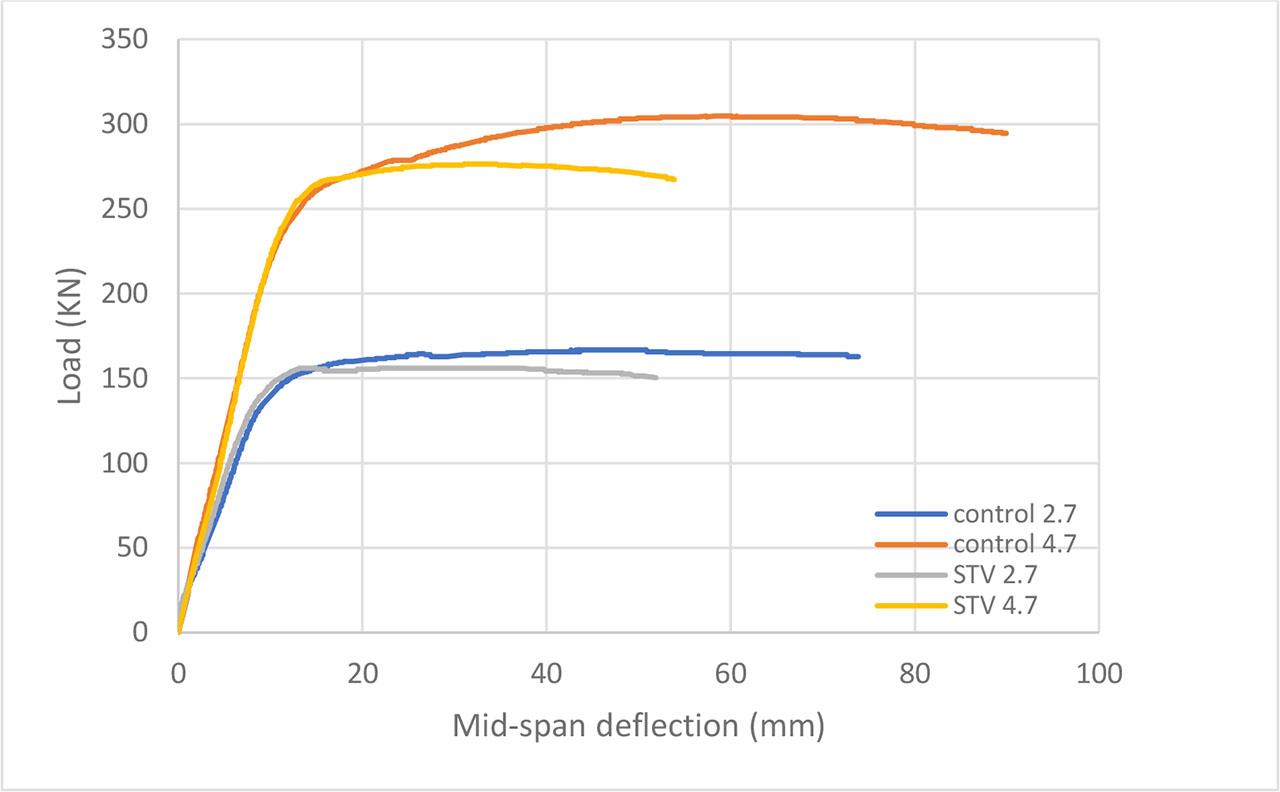
Load-deflection curves for control specimens compared to STV specimens.
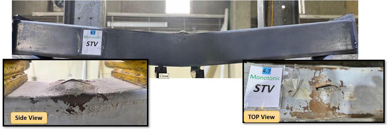
As shown in Fig. 10, the specimens labelled STH 2.7 mm and STH 4.7 mm, both with horizontal notches placed in the compression zone, displayed a different flexural behaviour compared to the vertical notch specimens. The notches, oriented parallel to the longitudinal axis of the beam, resulted in a delayed onset of failure and a more gradual reduction in load capacity.
The 4.7 mm thick specimen exhibited a load-displacement curve like the control specimen, indicating that the horizontal notch had a relatively minor impact on its flexural performance. The specimen retained a plateau before a gradual decline, showing that the increased wall thickness helped resist the detrimental effects of the notch.
While the 2.7 mm thick specimen showed a reduction in load capacity, it exhibited less severe degradation compared to its vertical counterpart in STV specimens. This suggests that horizontal notches in the compression zone are less detrimental than vertical notches, as they do not initiate local buckling as aggressively or disrupt the composite interaction between the steel tube and the concrete core.
These findings highlight that while horizontal notches affect the flexural performance of CFST specimens, their impact is less severe than that of vertical notches, particularly when the steel tube thickness is increased.
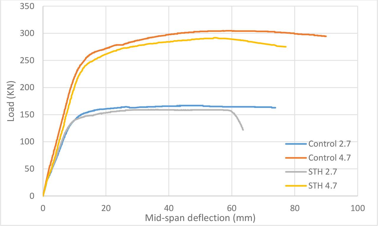
Load-deflection curves for control specimens compared to STH specimens.
As shown in Fig. 11, the specimens labelled SBV 2.7 mm and SBV 4.7 mm, which contain vertical notches positioned at the bottom (tension zone), exhibited notable differences in flexural performance. This behaviour is primarily attributed to the critical role of the tension zone, which is subjected to maximum flexural tensile stresses during bending. The presence of imperfections in this region significantly affects the structural response.
The SBV 2.7 mm specimen demonstrated a substantial deterioration in flexural performance. The corresponding load-load-displacement curve reveals an early and sharp decline in load-bearing capacity, indicating premature failure initiated at the bottom notch. This behaviour highlights the severe influence of imperfections in the tensile zone of thin-walled CFST sections, where reduced wall thickness contributes to lower ductility and diminished energy absorption capacity.
The SBV 4.7 mm specimen exhibited a performance trend relatively closer to the unnotched control specimen; however, the load–load–load-displacement curve reveals a noticeable, not slight, drop in both peak and post-peak ductility. This suggests that while the increased wall thickness helped mitigate the negative impact of the notch by enhancing confinement and increasing the moment of inertia, it did not entirely neutralise its detrimental effect. The notch still influenced the specimen’s flexural behaviour, particularly regarding reduced energy dissipation and delayed but evident crack propagation.
These findings emphasise the essential role of wall thickness in moderating the adverse effects of imperfections in the tension zone. Although thicker steel tubes improve flexural capacity and resistance to local failure, they do not eliminate the influence of geometrical defects when positioned in critical stress zones under bending loads.
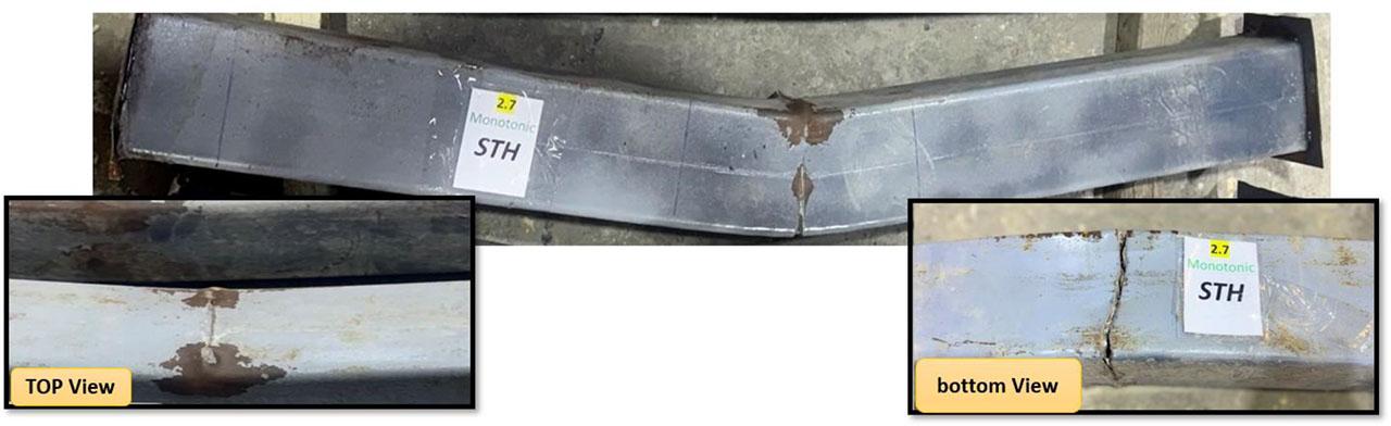
As shown in Fig. 12, the specimens labelled SBH 2.7 mm and SBH 4.7 mm, with horizontal notches positioned at the bottom (tension zone), exhibited significant reductions in peak load and stiffness compared to their control counterparts. The horizontal notches are aligned with the direction of maximum tensile stress, acting as initiation points for tensile failure, accelerating failure and reducing overall ductility.
The 2.7 mm thick specimen showed a steep decline in the load-displacement curve after reaching the peak, signifying brittle failure behaviour. This indicates that the notch significantly initiated failure, causing a rapid loss of load-bearing capacity.
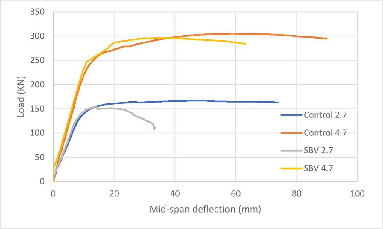
Load-deflection curves for control specimens compared to SBV specimens.
The 4.7 mm thick specimen performed better but still showed a reduction in flexural strength and post-yield ductility compared to the control specimen. While the thicker wall provided some resistance to the notch’s effects, the overall performance still suffered due to the presence of the horizontal notch in the tension zone.
Load-deflection curves for control specimens compared to SBH specimens.
Under monotonic loading conditions, the failure mechanism of hollow square steel tube beams is predominantly characterised by localised outward buckling occurring within the compression zone beneath the applied load points.
For the beam with a wall thickness of 2.7 mm, Fig. 13a, failure initiated with a conspicuous outward bulging on the side surface directly below the load application area. This lateral deformation progressively intensified as the load increased, marking a clear transition from elastic behaviour to localised plastic buckling. Due to the limited thickness, the steel wall exhibited insufficient resistance to compressive stresses, resulting in a rapid decline in stiffness and an extensive deformation zone, as distinctly observable from both sides and top perspectives.
In contrast, the beam with a 4.7 mm wall thickness Fig. 13b demonstrated a markedly delayed onset of buckling, accompanied by a less severe deformation pattern. The outward bulging was confined to a smaller localised region and manifested only at higher load levels. The increased wall thickness substantially improved the structural stability, mitigating the extent of lateral deformation and enhancing the beam’s flexural performance.
Notably, when viewed from the top, the buckling manifests as an inward indentation, a phenomenon that starkly contrasts with the outward bulging observed from the side view. This directional disparity in deformation profiles between the top and side observations is a defining characteristic of the localised buckling response in hollow steel tube beams subjected to monotonic bending loads.
Overall, this comparative analysis underscores the paramount influence of wall thickness on sidewall stability and significantly augments the flexural capacity of hollow square steel tube beams under monotonic loading.
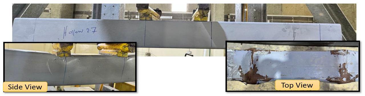
Failure Behaviour of Hollow Steel Tube Beams with thickness 2.7.
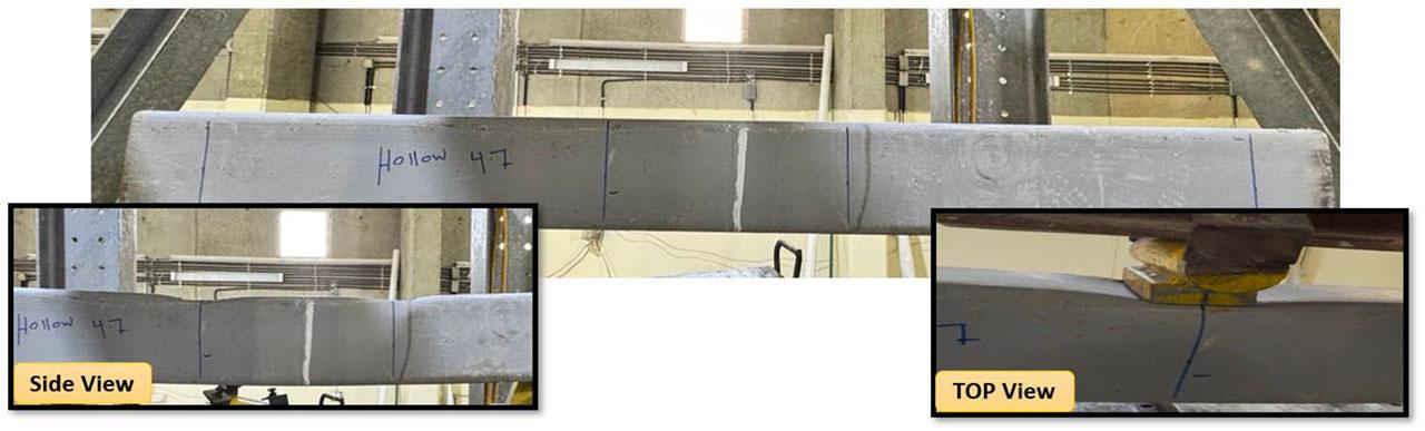
Failure Behaviour of Hollow Steel Tube Beams with thickness 4.7.
In the 2.7 mm thick specimen, Fig. 14a, failure initiated with pronounced local outward buckling at the top surface between the loading points, where compressive stresses were concentrated. This deformation became increasingly plastic, indicating a significant reduction in stiffness and a transition toward yielding. Additionally, a visible crack was observed along the bottom tension zone, suggesting that the tensile strength of the steel wall was exceeded. The thinness of the steel tube contributed to its vulnerability to compressive buckling and tensile cracking, making the overall behaviour less stable and more localised in nature.
In contrast, the 4.7 mm thick specimen Fig. 14b showed a more stable response with less severe buckling and no visible tension cracking. The increased thickness enhanced resistance to deformation and improved overall ductility.
The concrete infill significantly improved structural performance by restraining local buckling, delaying crack formation, and enhancing stiffness and energy absorption. These effects were especially pronounced in the thicker section.
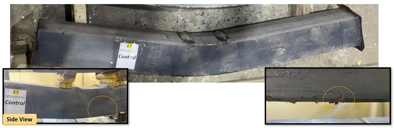
Failure Behaviour of Control Steel Tube Beams with thickness 2.7.
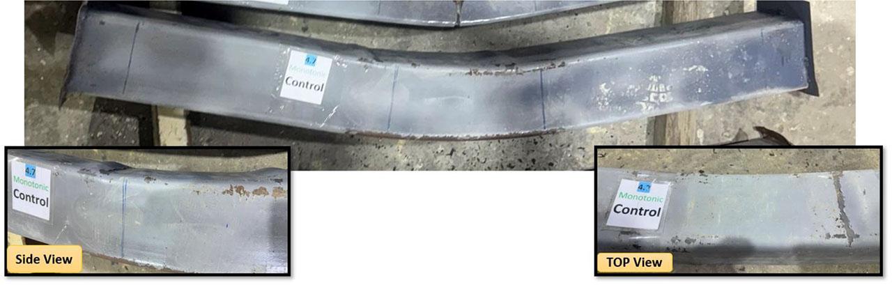
Failure Behaviour of Control Steel Tube Beams with thickness 4.7.
In the 2.7 mm thick specimen Fig. 15a, failure was dominated by early inward buckling combined with outward bulging around the notch edges, driven by stress redistribution. The thin wall lacked sufficient post-buckling strength, leading to tearing and rapid localised collapse.
The 4.7 mm specimen Fig. 15b exhibited delayed buckling and more distributed deformation. Though tearing was also present, the thicker wall provided greater resistance, enabling more gradual failure and better stress redistribution.
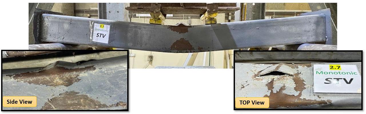
Failure behaviour of STV beams with vertical notches in the compression zone with thickness 2.7.
Failure behaviour of STV beams with vertical notches in the compression zone with thickness 4.7.
The specimen with a 2.7 mm Fig. 16a wall thickness exhibited significant susceptibility to the notch. Large global deflection was observed, accompanied by local outward buckling centred at the notch in the compression zone. As loading progressed, mid-span tearing developed in the bottom tension zone. Eventually, the failure zones from the top and bottom met, resulting in an apparent merging between the notch and the tensile rupture, forming a continuous failure path through the section depth. This phenomenon, visibly captured in the observed specimen, reflects a combined failure mechanism involving compressive instability and tensile fracture, intensified by the limited wall stiffness.
In contrast, the 4.7 mm specimen Fig. 16b showed greater localised failure resistance. Although minor outward deformation occurred around the notch, no severe propagation or tearing was observed. The thicker wall allowed better stress redistribution, preserving the overall structural integrity and enabling a more uniform and ductile flexural response.
Failure behaviour of STH beams with horizontal notches in the compression zone with thickness 2.7.
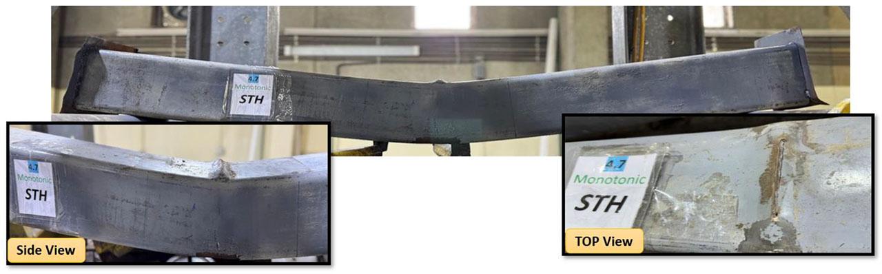
Failure behaviour of STH beams with horizontal notches in the compression zone with thickness 4.7.
The 2.7 mm specimen Fig. 17a exhibited significant downward deflection, widening at the notch, and early signs of tearing. The reduced wall stiffness allowed stress concentration in the tension zone, while local upward buckling also developed above the notch in the compression zone, between the loading points. A combination of tensile cracking and compressive instability drove the failure.
The 4.7 mm specimen Fig. 17b improved performance with stable notch behaviour and a more ductile flexural response. However, local buckling was again observed above the notch, though less pronounced. The thicker wall enhanced stress redistribution, delaying both crack development and buckling.
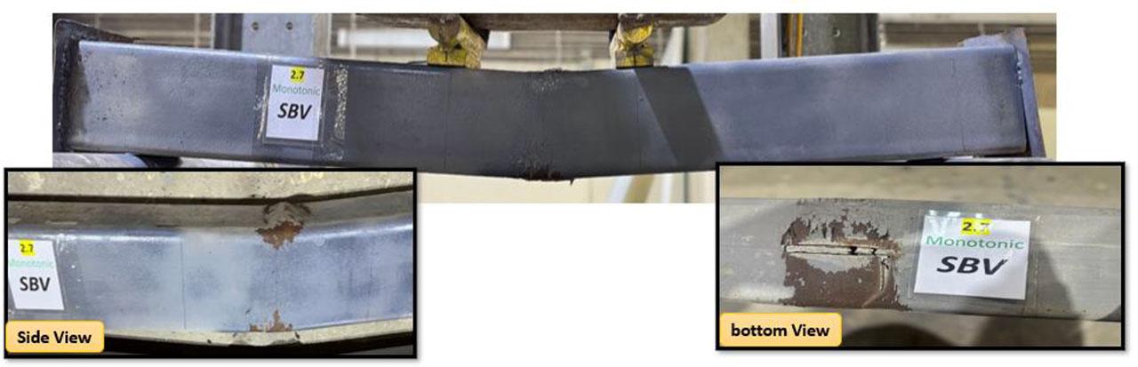
Failure behaviour of SBV beams with vertical notches in the tension zone with thickness 2.7.
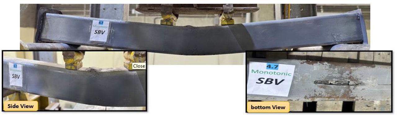
Failure behaviour of SBV beams with vertical notches in the tension zone with thickness 4.7.
The 2.7 mm specimen Fig. 18a exhibited notable global deflection under monotonic bending. Early in the loading process, the horizontal notch widened, leading to visible surface damage and partial tearing concentrated around the defect. The thin steel wall lacked sufficient tensile strength to counteract the localised stress concentration, resulting in progressive crack propagation along the tension face. Furthermore, local buckling was observed in the compression zone above the notch, indicating a combined failure mode involving tensile rupture and compressive instability.
The 4.7 mm specimen Fig. 18b, while demonstrating greater stiffness and improved resistance to overall deformation, also experienced severe localised failure at the notch. Contrary to initial impressions, closer inspection revealed a substantial tear emanating from the notch, characterised by clear material separation and extended cracking in the tension region. Despite the increased wall thickness, the horizontal notch was a critical weak point, initiating localised tensile rupture. Additionally, local compressive buckling developed above the notch, although it was less dominant in the overall failure response.
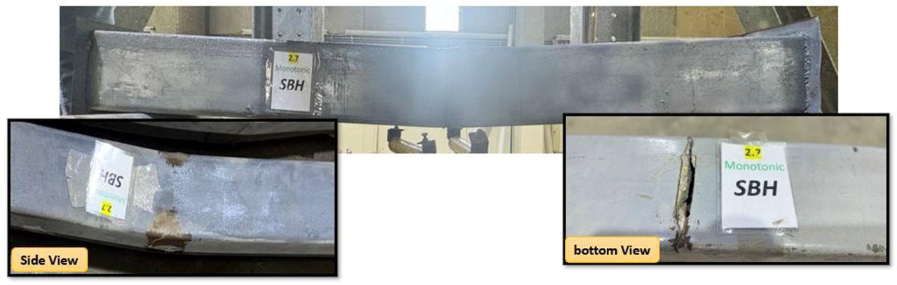
Failure behaviour of SBH beams with horizontal notches in the tension zone with thickness 2.7.
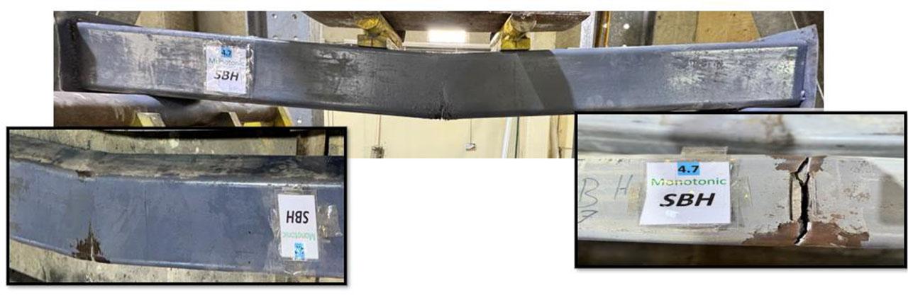
Failure behaviour of SBH beams with horizontal notches in the tension zone with thickness 4.7.
This study presented an experimental investigation into the flexural behaviour of concrete-filled steel tube (CFST) beams containing initial imperfections in the form of artificial notches. Twelve specimens-varying in notch orientation, location, and steel wall thickness-were tested under four-point bending. The main conclusions are as follows:
- 1)
Notch location sensitivity:
Notches located in the tension zone had the most detrimental impact on performance.
The most severe case, SBH-2.7, exhibited:
A 30.12% reduction in ultimate load,
A 76.19 decrease in deflection indicating a major loss in ductility.
These notches acted as crack initiators and significantly reduced the energy absorption capacity.
- 2)
Influence of notch orientation:
Horizontal notches were generally more destructive than vertical ones, particularly in the tension zone.
Their alignment across the cross-section facilitated early fracture and reduced post-yield resistance.
In contrast, vertical notches—especially in the compression zone—had a more stable and delayed failure behaviour.
- 3)
Effect of Wall Thickness
Increasing the steel wall thickness from 2.7 mm to 4.7 mm enhanced overall performance:
Improved strength by up to 85%,
Increased ductility and delayed buckling.
However, thicker walls alone did not fully eliminate the negative effects of notches—especially in tension-dominant areas.
- 4)
Contribution of Concrete Core
The concrete infill significantly improved stiffness, load capacity, and resistance to local failure.
Compared to hollow tubes, CFST beams showed:
Up to 72.71% higher strength.
Greater confinement and stability under bending.
- 5)
Engineering Implications
Even small imperfections, such as notches from fabrication or damage, can drastically reduce CFST performance.
Structural design should:
Instead, designers should account for possible imperfections in high-stress regions, include adequate safety factors, and implement strict quality control measures during fabrication and installation.
Extend the study using finite element modelling to simulate different notch shapes and loading conditions.
Explore strengthening techniques (e.g., FRP wraps or localized steel reinforcements) for damaged CFST elements.
Investigate the fatigue and cyclic behaviour of notched CFST beams to enhance design for seismic and dynamic applications.