
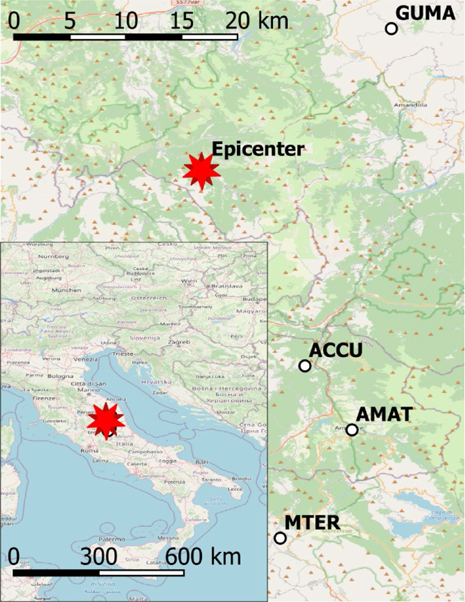
Figure 1.
Distribution of the earthquake epicenter and GNSS stations
Table 1.
Parameters of the analyzed earthquake (after Kudlacik et al. 2019)
| Parameter | Value |
|---|---|
| Date | 10.26.2016 19:18:08 UTC |
| Location | 3 km NNW of Visso, Italy |
| Epicenter | 42.862°N 13.096°E |
| Depth | 8 km |
| Magnitude | 6.1 |
| Focal mechanism | normal, NP1: 333°/40°/−92°, NP2: 155°/50°/−89° |
Table 2.
Summary of names, azimuths, and distances for GNSS stations and seismographs (Kudlacik et al. 2019)
| Sensor name | Azimuth of epicenter | Distance [km] | ||
|---|---|---|---|---|
| GNSS station | Seismograph | To Epic. epicenter | Between Sens. sensors | |
| ACCU | IT.ACCU | 158.9° | 25.4 | 0.08 |
| AMAT | IT.AMT | 157.0° | 33.7 | 0.77 |
| GUMA | IV.GUMA | 45.6° | 24.0 | 0.49 |
| MTER | IV.RM33 | 171.5° | 44.9 | 0.39 |
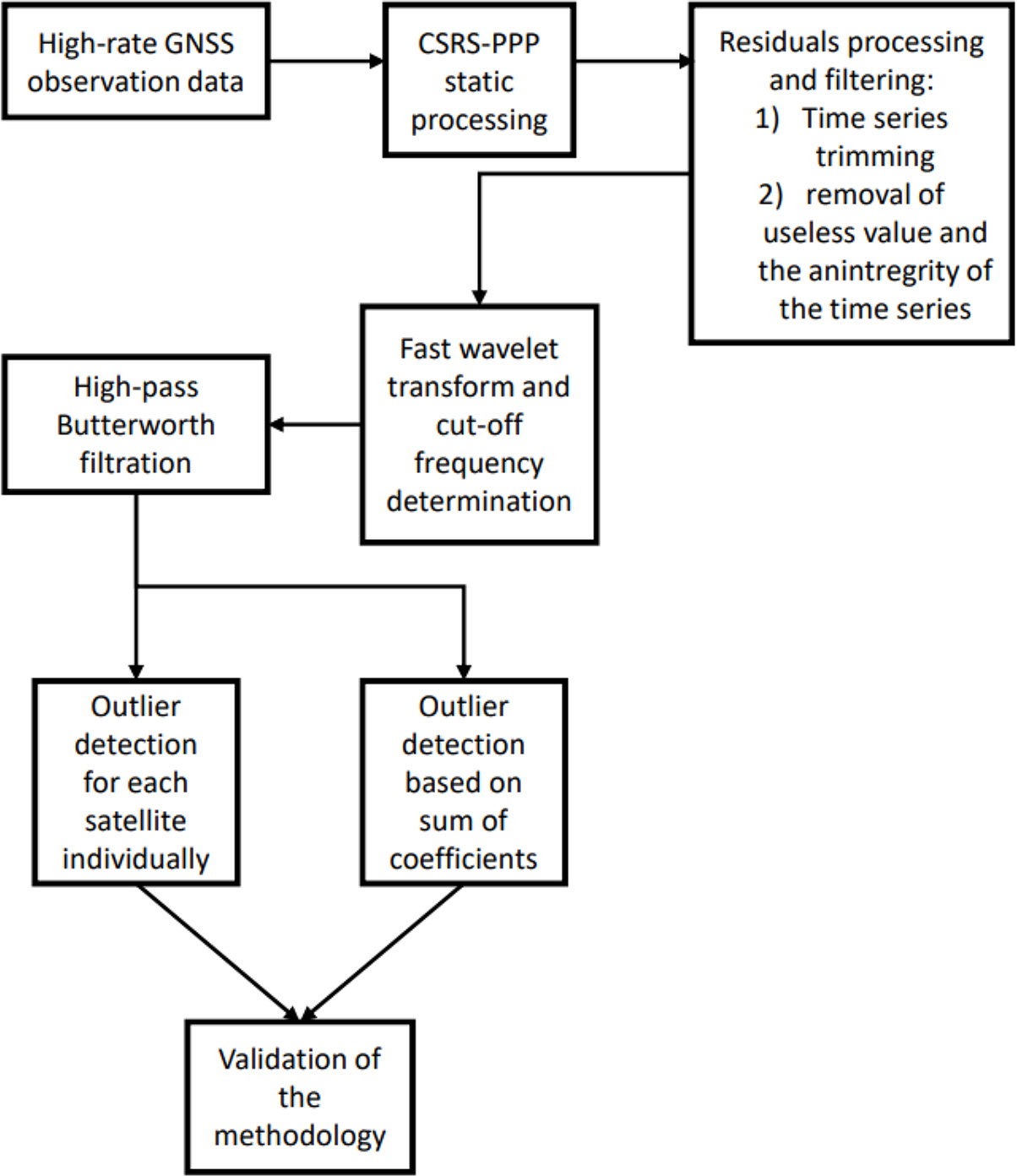
Figure 2.
Flow chart of the proposed method
Table 3.
Computational strategy in CSRS-PPP
| Section | Description |
|---|---|
| Mask elevation | 7.5° |
| Interval | 0.1 s |
| Observations | GPS + GLONASS |
| Tropospheric modeling | VMF1 (Boehm, Werl, and Schuh 2006) + horizontal and zenith gradient estimation |
| Ionosphere modeling | Estimated |
| Use of the precise products | Products from IGS + CSRS-PPP clock combination (Banville 2020) |
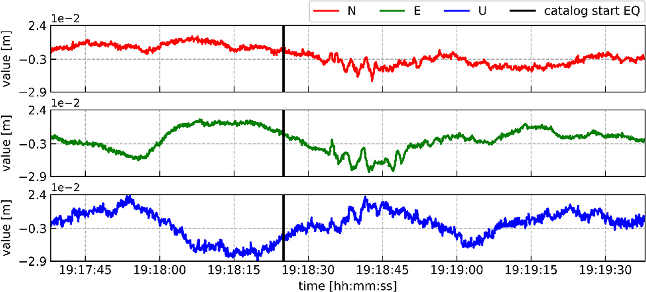
Figure 3.
Coordinate differences between a priori coordinates from the RINEX file header and estimated coordinates for each epoch obtained from the kinematic PPP. The vertical dashes define the earthquake ranges obtained from the seismograph for the ACCU station
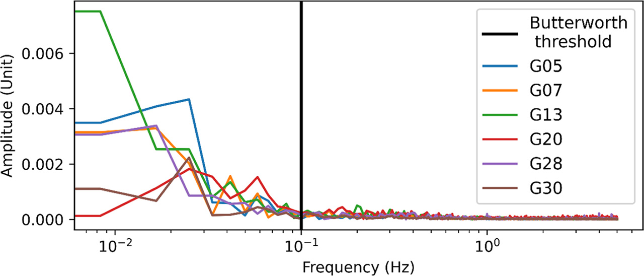
Figure 4.
Fast wavelet transform performed for a series of resistances for all satellites at frequency L1 for the ACCU station
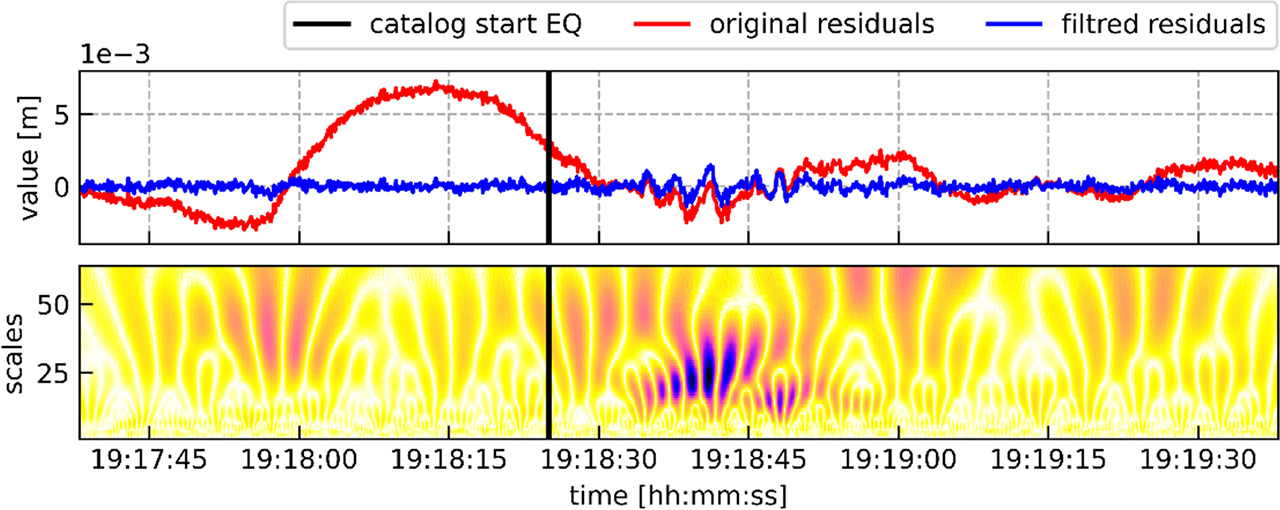
Figure 5.
GNSS observation residuals (red) and filtered residuals (blue, top panel), continuous wavelet transform scalar for scales 1–64 (bottom panel) for filtered observation residuals for the satellite G05 at frequency L1W for the ACCU station
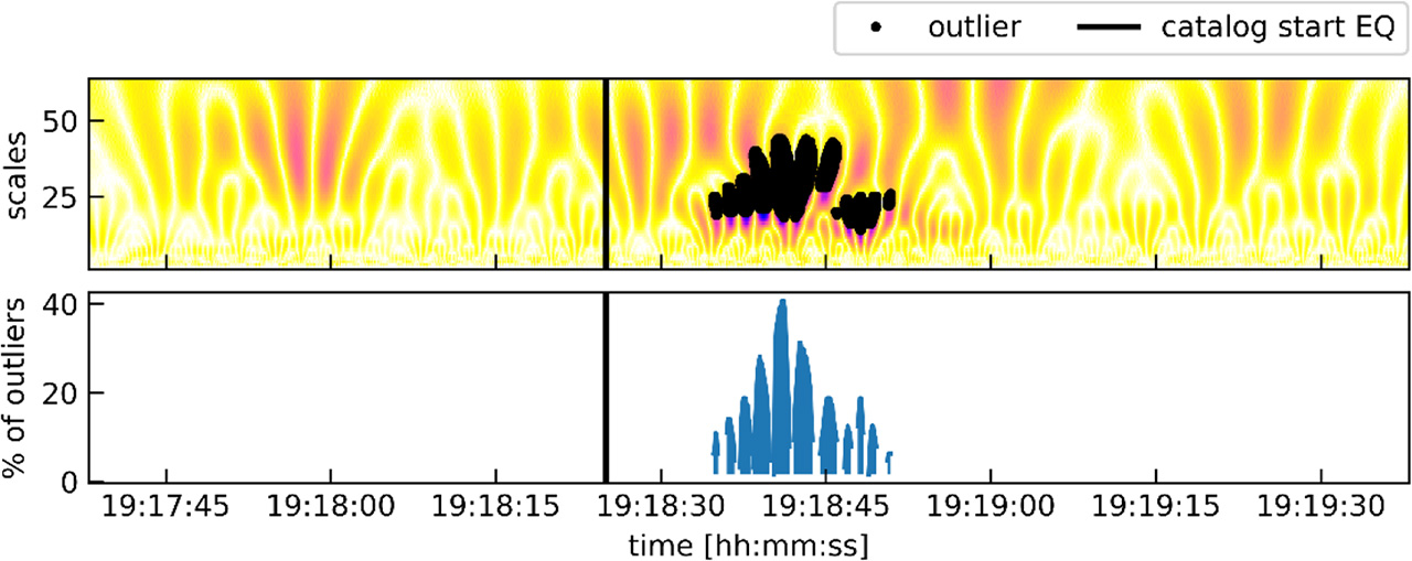
Figure 6.
Detected outliers derived from the scalogram coefficients of the filtered GNSS observation residuals for satellite G05 at frequency L1W (top panel) and the percentage of scalogram coefficients classified as outliers (bottom panel)
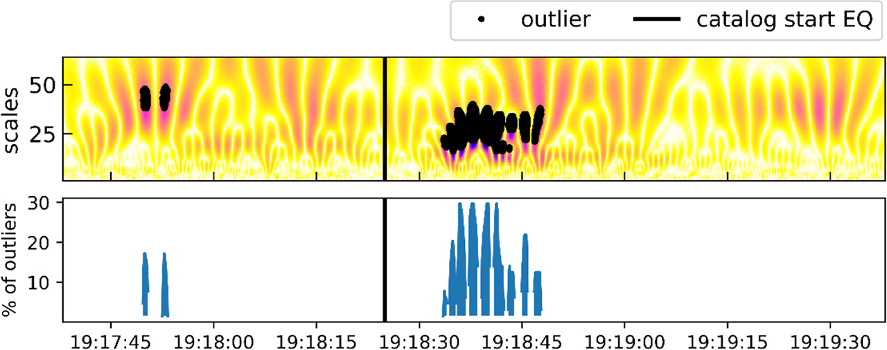
Figure 7.
Detected outliers obtained from summed scalogram coefficients for all satellites (top panel) and percentage of scalogram coefficients classified as outliers (bottom panel)
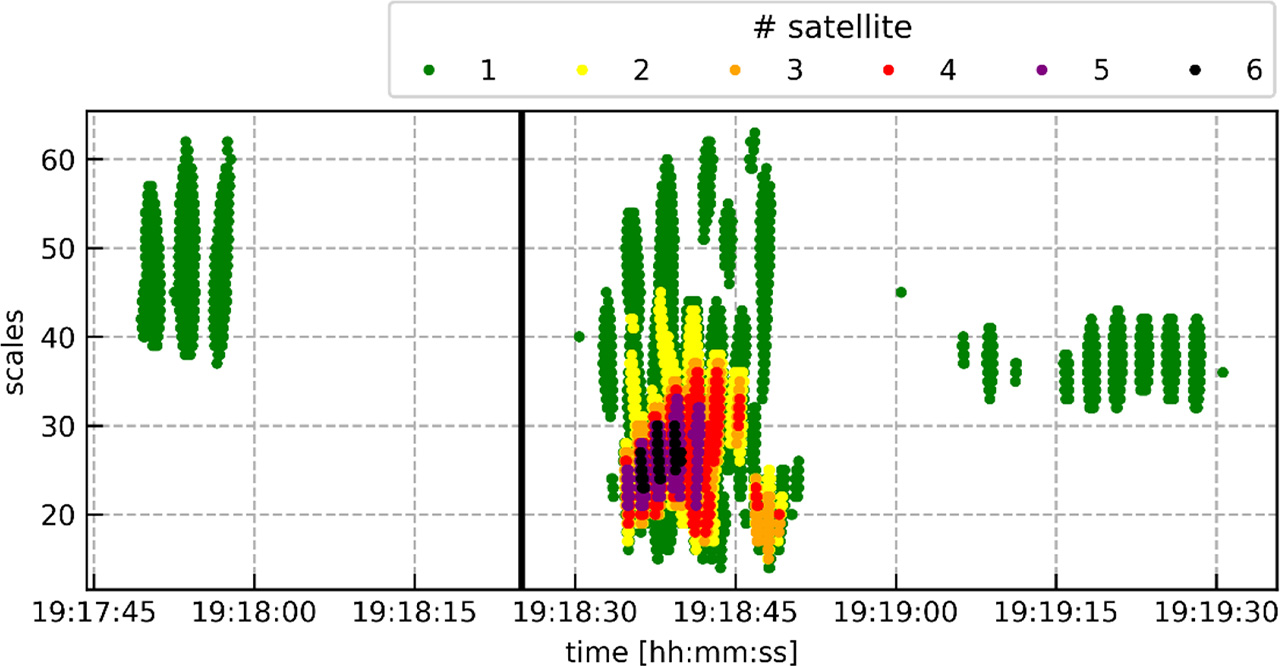
Figure 8.
Color combinations of outliers determined by a certain number of satellites on the L1W frequency for ACCU stations. Colors used; green: one satellite, yellow: two, orange: three, red: four, purple: five, black: six satellites.
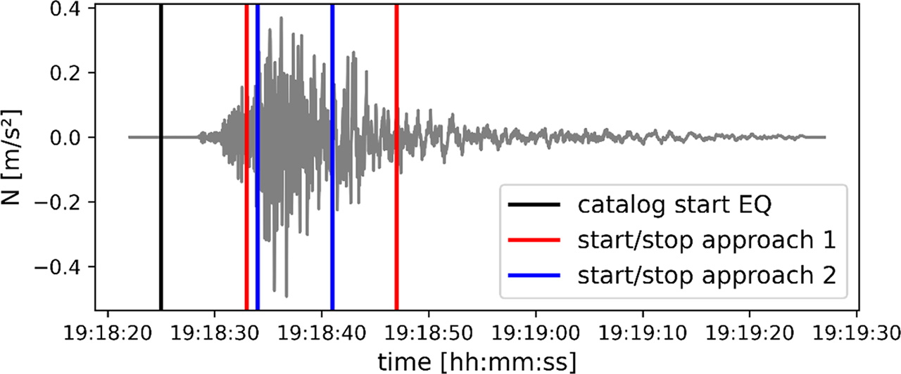
Figure 9.
Accelerations for the N component of the seismograph (black) and the designated earthquake range for the ACCU station detected using GNSS residuals