
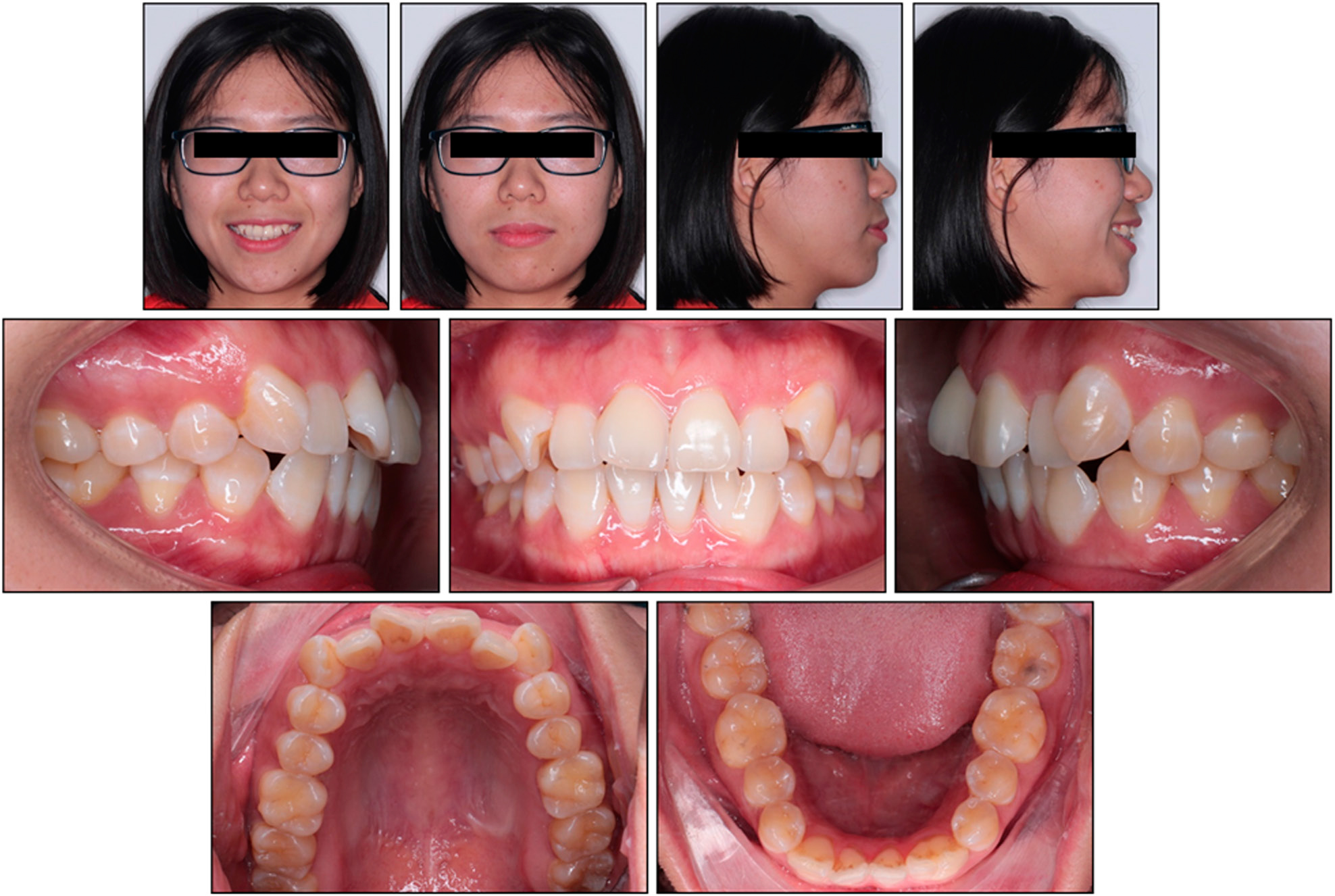
Figure 1.
Initial extra- and intra-oral clinical photographs.
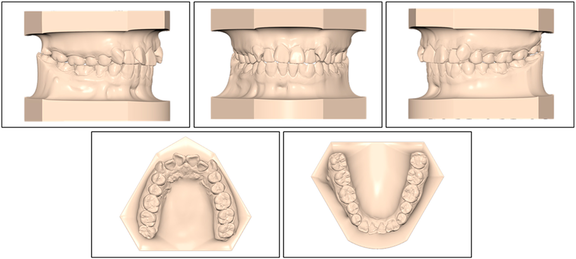
Figure 2.
Pretreatment maxillary and mandibular study models.
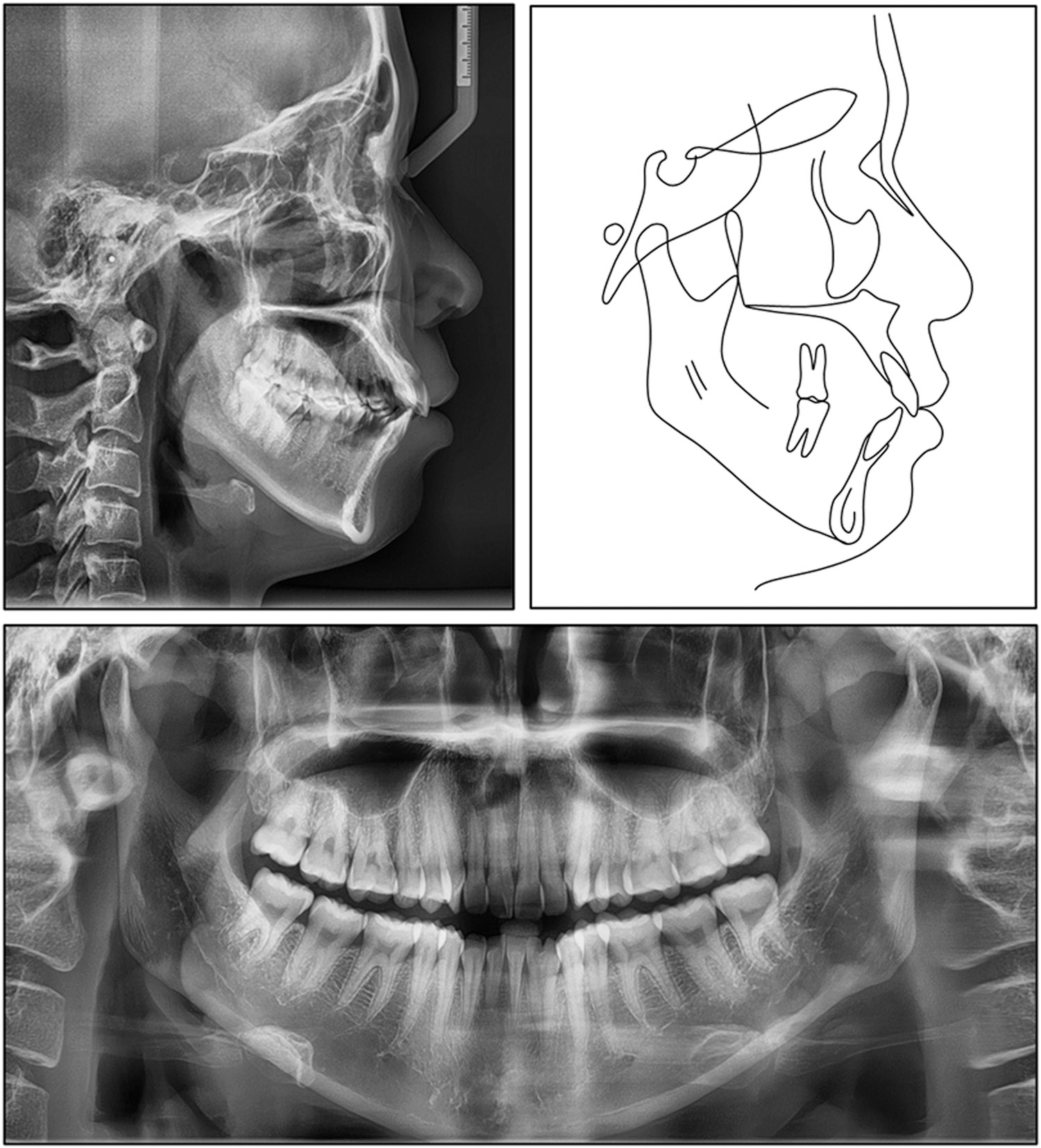
Figure 3.
Pretreatment lateral cephalogram, panoramic radiograph, and tracing.
Table I.
Cephalometric measurements: pretreatment and post-treatment values compared with population norms
| Measurement | Pretreatment | Post-treatment | Normal |
|---|---|---|---|
| Skeletal | |||
| SNA (°) | 83.52 | 83.02 | 81.08 ± 3.7 |
| ANB (°) | 4.36 | 4.04 | 2.46 ± 1.8 |
| SNB (°) | 79.16 | 78.97 | 79.17 ± 3.8 |
| Wits appraisal (mm) | –0.17 | 0.21 | –0.33 ± 2.7 |
| Pog to N-Perp (°) | –4.46 | –6.05 | –1.8 ± 2.5 |
| A to N-Perp (°) | 2.15 | 1.27 | 0.4 ± 2.3 |
| Gonial angle (°) | 129.07 | 129.21 | 124.31 ± 5.4 |
| FMA (°) | 33.86 | 33.77 | 25 ± 4 |
| Bjork sum (°) | 402.49 | 402 | 397.16 ± 3.6 |
| Dental | |||
| Cant of occlusal plane (°) | 8.51 | 8.21 | 9.3 ± 3.8 |
| Upper incisal display (mm) | 4.27 | 1.72 | 2.5 ± 1.5 |
| L1 to NB (°) | 31.49 | 25.33 | 25 ± 5 |
| L1 to NB (mm) | 9.31 | 6.17 | 4 ± 2 |
| U1 to NA (°) | 23.35 | 15.87 | 22 ± 5 |
| U1 to NA (mm) | 6.98 | 3.29 | 4 ± 3 |
| Interincisal angle (°) | 120.8 | 134.75 | 128 ± 5.3 |
| IMPA (°) | 89.85 | 84.35 | 90 ± 3.5 |
| U1 to SN (°) | 106.87 | 98.89 | 105.28 ± 6.6 |
| Overbite (mm) | 2.62 | 2.26 | 2 ± 2 |
| Overjet (mm) | 4.2 | 3.02 | 2 ± 2 |
| Soft-tissue | |||
| Nasolabial angle (°) | 86.45 | 101.58 | 95 ± 5 |
| Upper lip to E-plane (mm) | 1.44 | –2.03 | 0 ± 2 |
| Lower lip to E-plane (mm) | 2.29 | –0.71 | 0 ± 2 |
1 A, point A; ANB, angle between N–A and N–B; E-plane, esthetic plane (Prn-Pog’); FMA, Frankfort-mandibular plane angle; IMPA, incisor-mandibular plane angle; L1, mandibular central incisor; NA, nasion-point A; NB, nasion-point B lines; N-Perp, line perpendicular to nasion; Pog, pogonion; SN, Sella–Nasion plane; SNA, angle between S–N and N–A; SNB, angle between S–N and N–B; U1, maxillary central incisor.
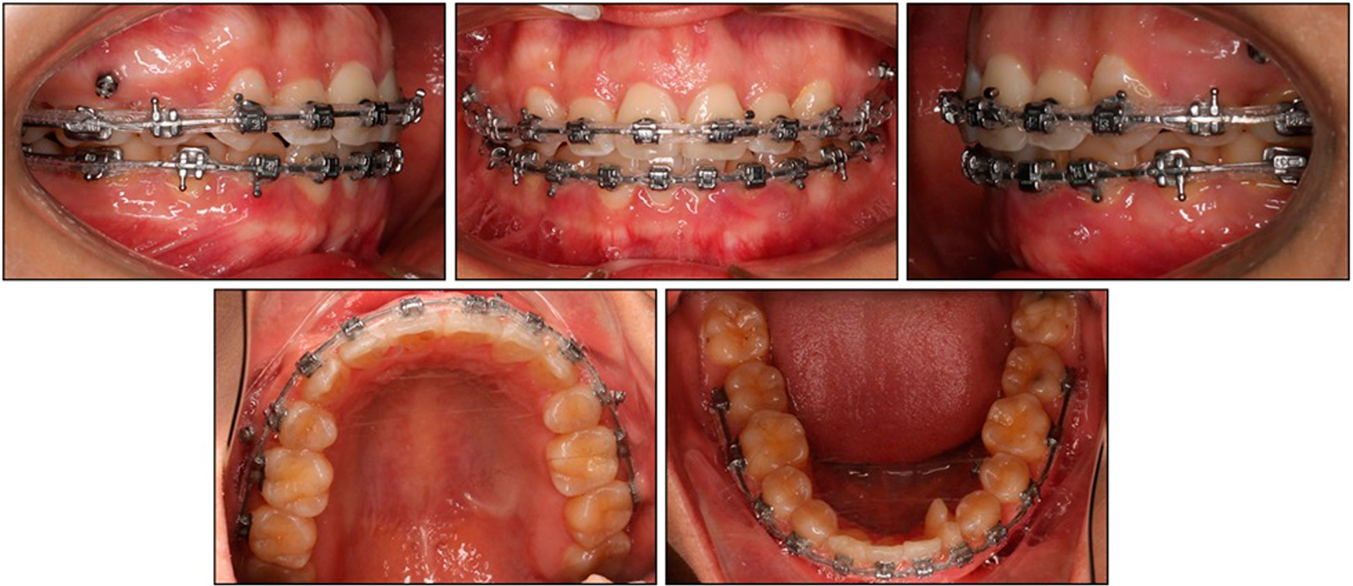
Figure 4.
Clinical photographs after 13 months of treatment.
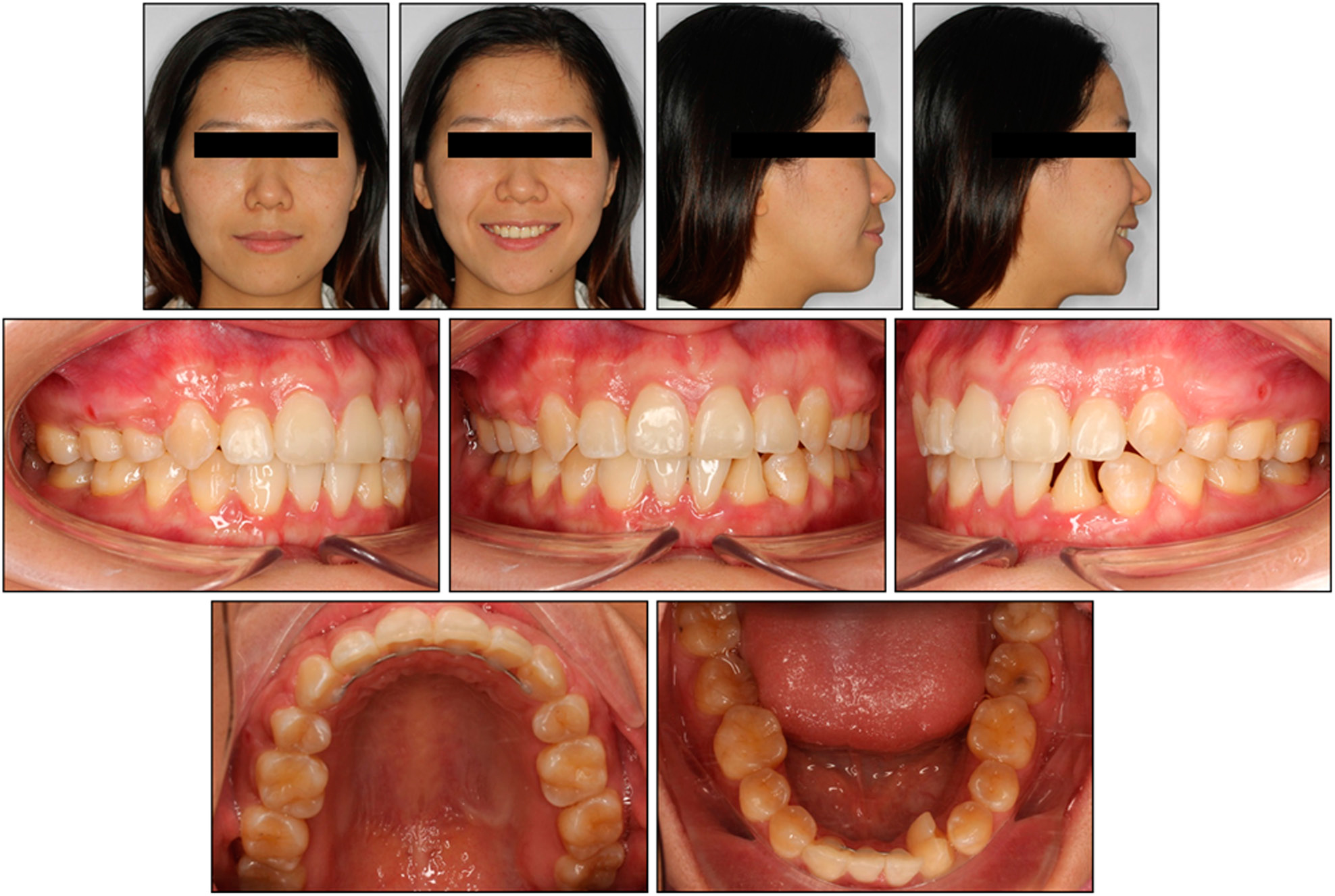
Figure 5.
Post-treatment extra- and intra-oral clinical photographs.
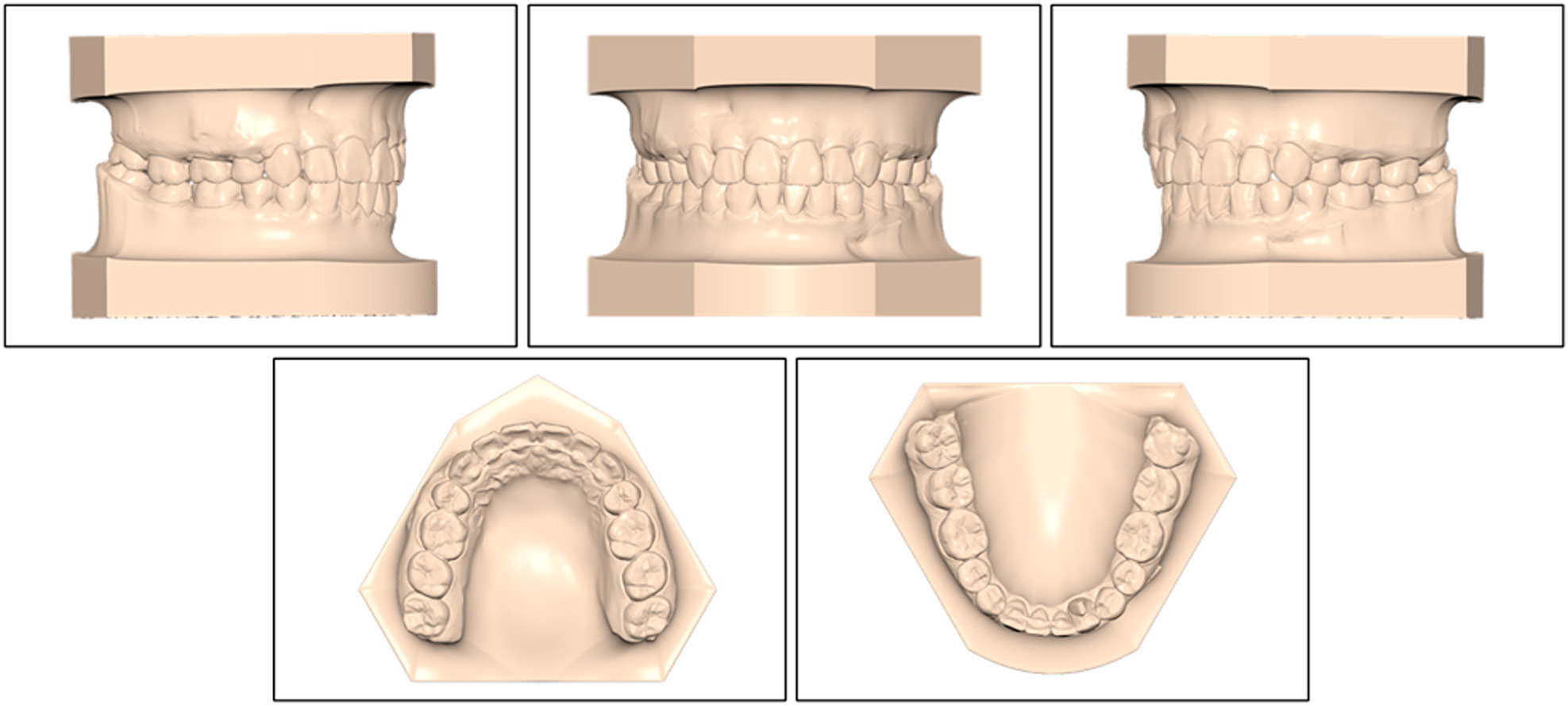
Figure 6.
Post-treatment maxillary and mandibular study models.
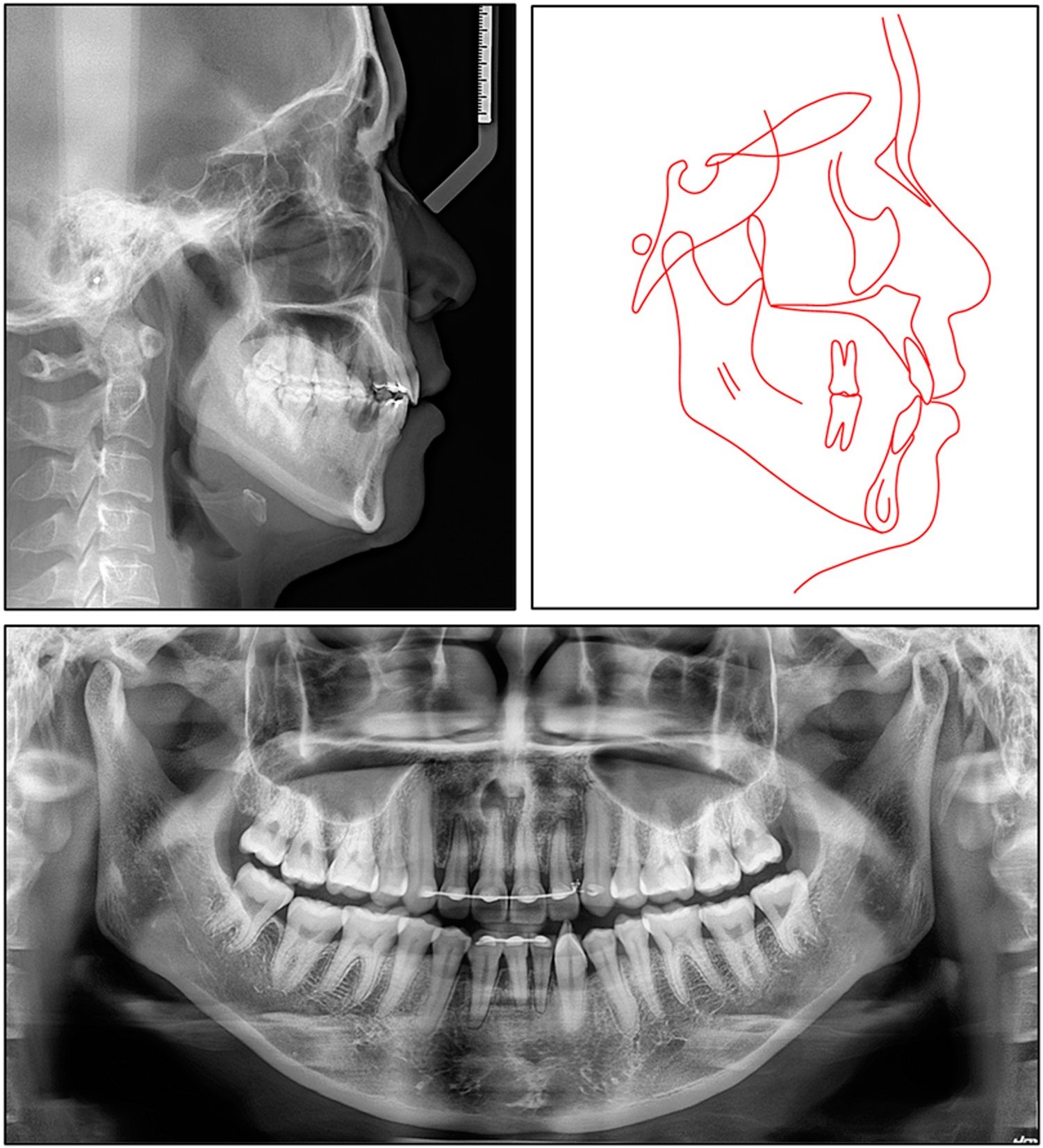
Figure 7.
Post-treatment lateral cephalogram, panoramic radiograph, and tracing.
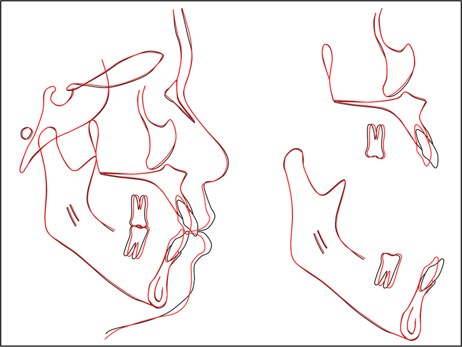
Figure 8.
Superimposed pretreatment and post-treatment cephalometric tracings.
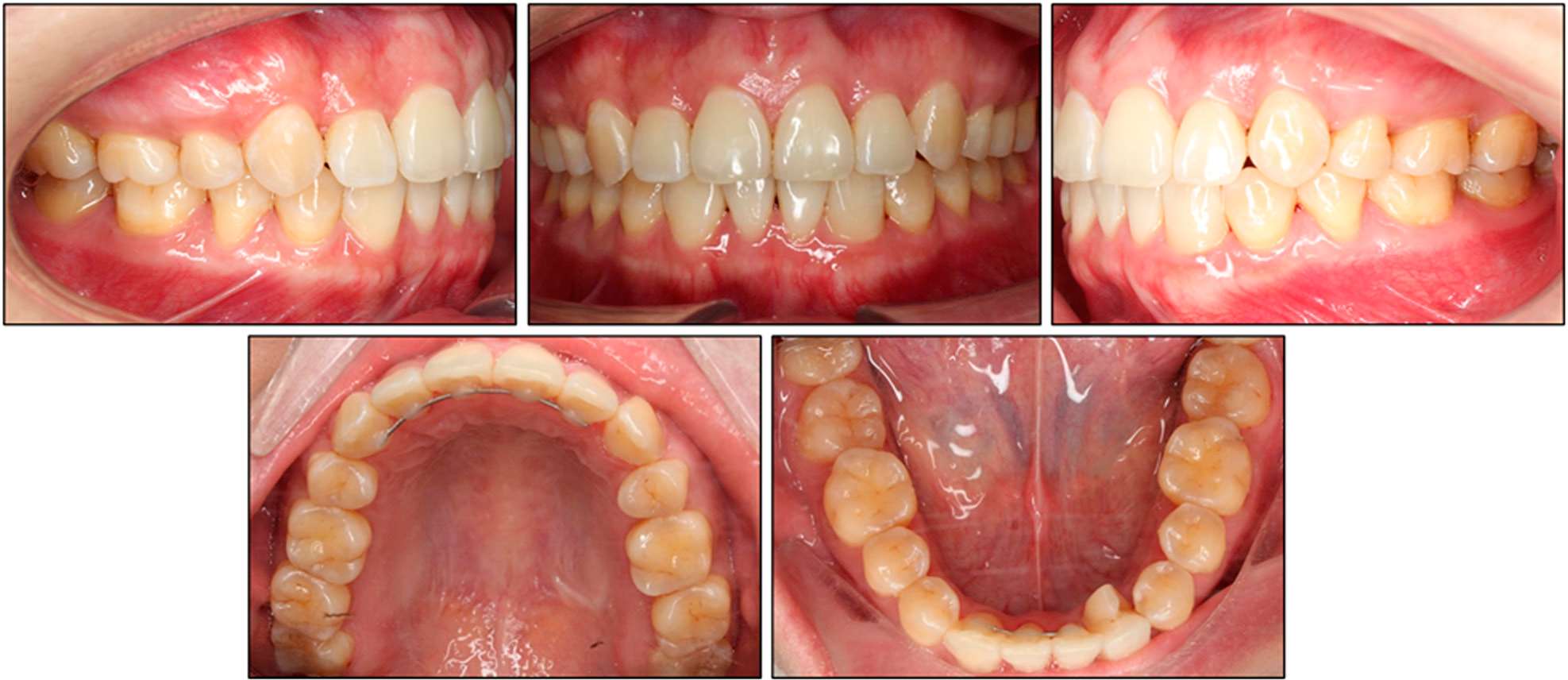
Figure 9.
Three-year retention intra-oral photographs.