
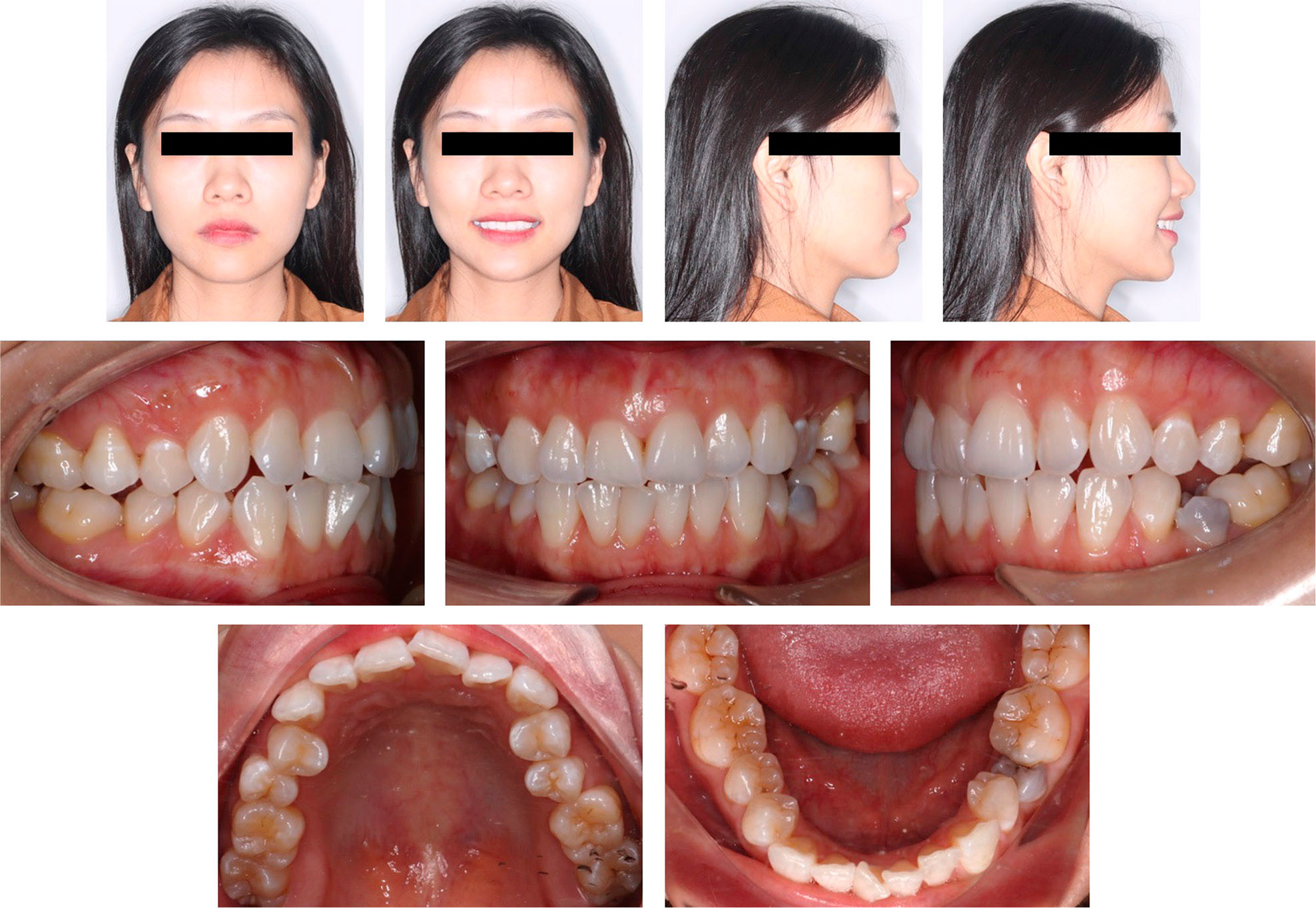
Figure 1.
Pretreatment facial and intraoral photographs.
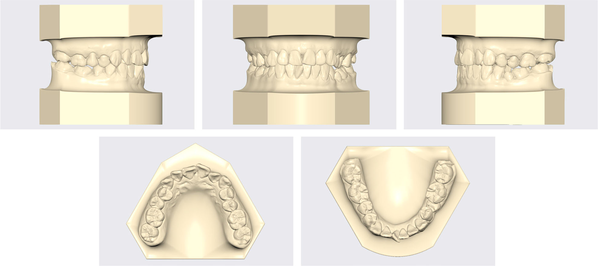
Figure 2.
Pretreatment models.
Table I.
Cephalometric measurements
| Pretreatment | Posttreatment | |
|---|---|---|
| Skeletal | ||
| SNA (°) | 81.8 | 81.8 |
| SNB (°) | 78.2 | 77.9 |
| ANB (°) | 3.6 | 3.9 |
| FMA (°) | 27.4 | 27.8 |
| Dental | ||
| U1-SN (°) | 101.7 | 96.7 |
| U1-NA (°) | 19.9 | 14.4 |
| U1-NA (mm) | 4.5 | 2.6 |
| L1-MP (°) | 96.8 | 94.1 |
| L1-NB (°) | 31.2 | 28.2 |
| L1-NB (mm) | 6.9 | 5.5 |
| U1-L1 (°) | 125.3 | 133.5 |
| Soft tissue | ||
| E-line/UL (mm) | -1.2 | -1.4 |
| E-line/LL (mm) | -0.7 | -0.2 |
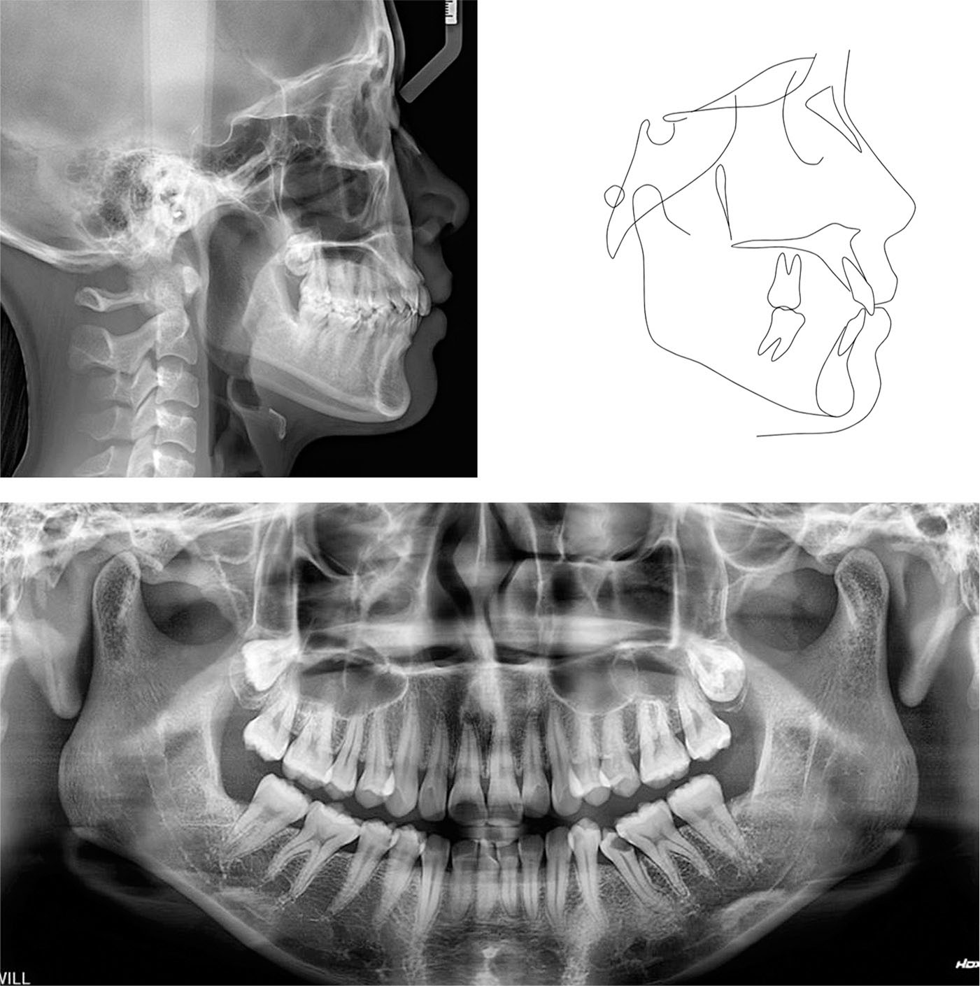
Figure 3.
Pretreatment radiographs and tracing.
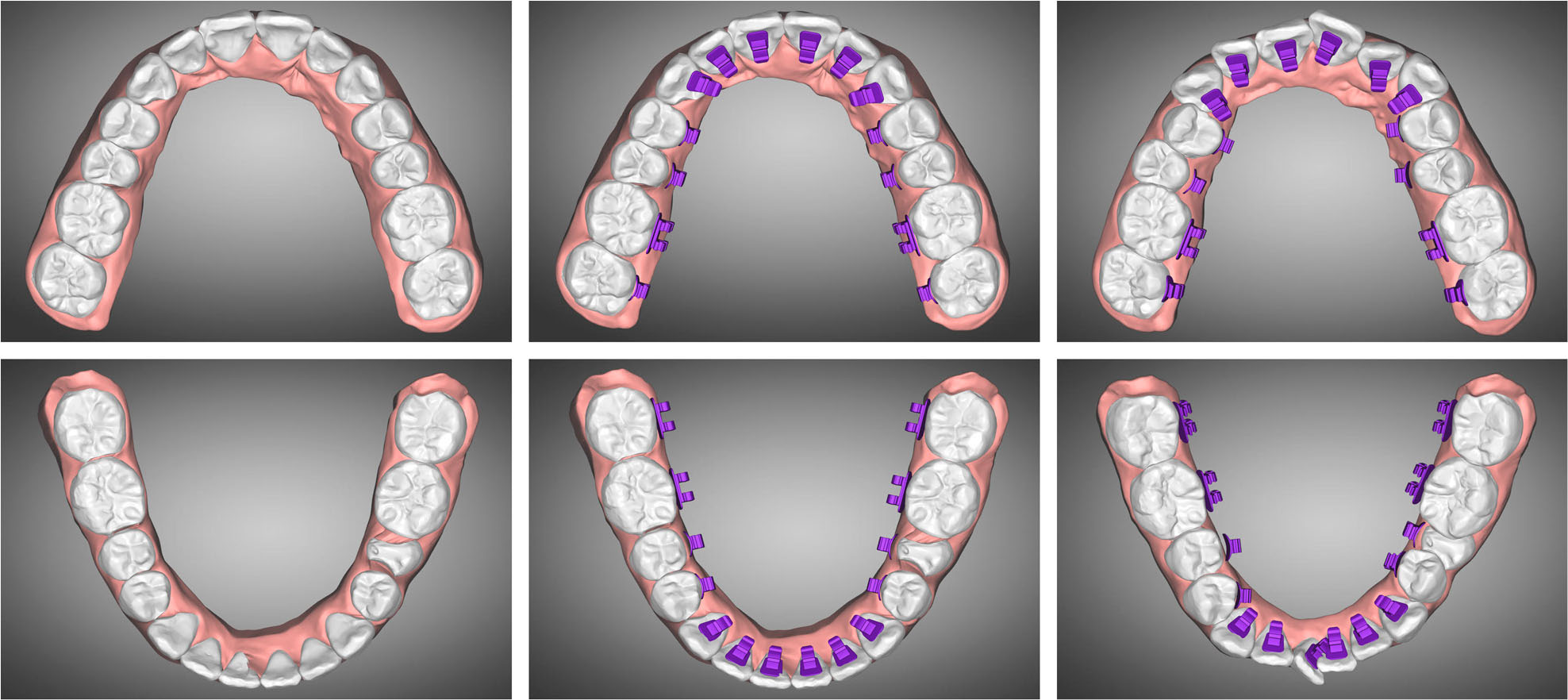
Figure 4.
Orthodontic setup and virtual bracket placement.
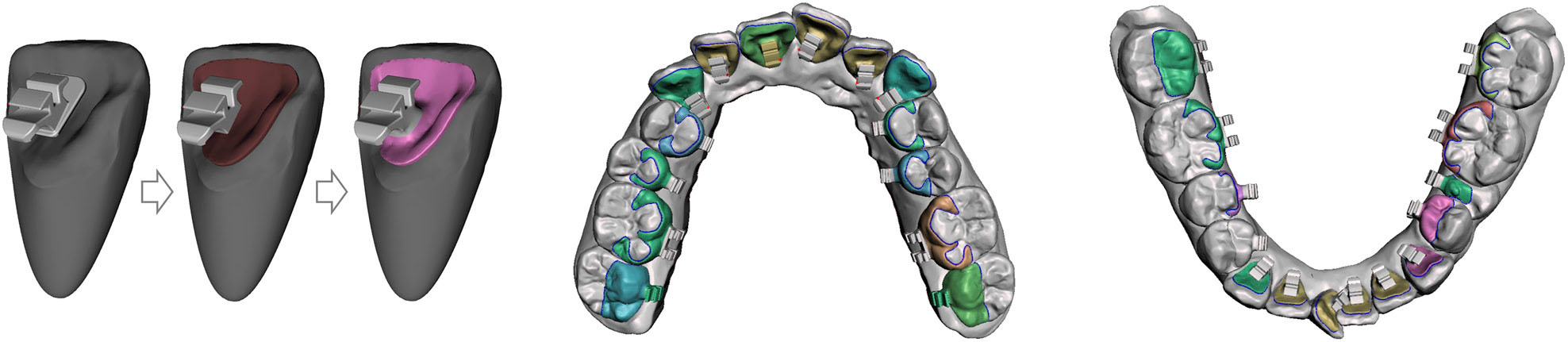
Figure 5.
Customised lingual bracket design.
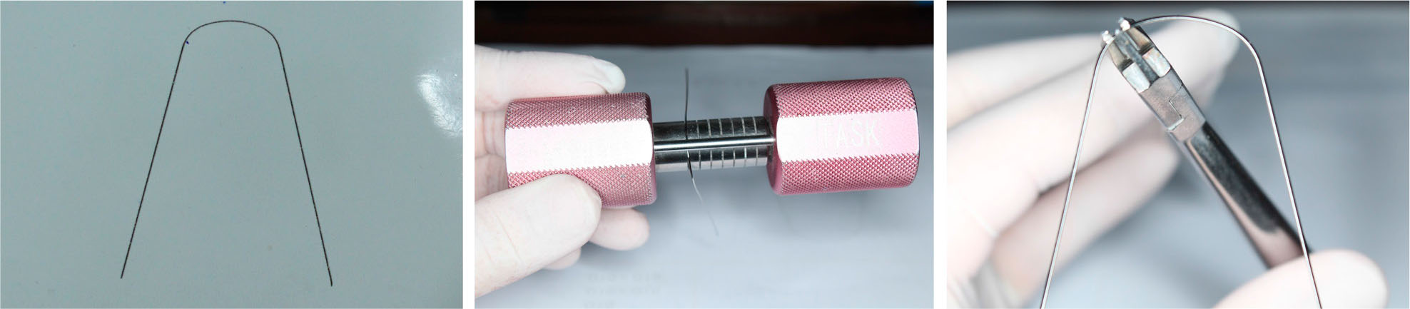
Figure 6.
Customised straight lingual arch wire forming.

Figure 7.
Upper incisor proclination and increased overjet after the levelling and alignment stage.
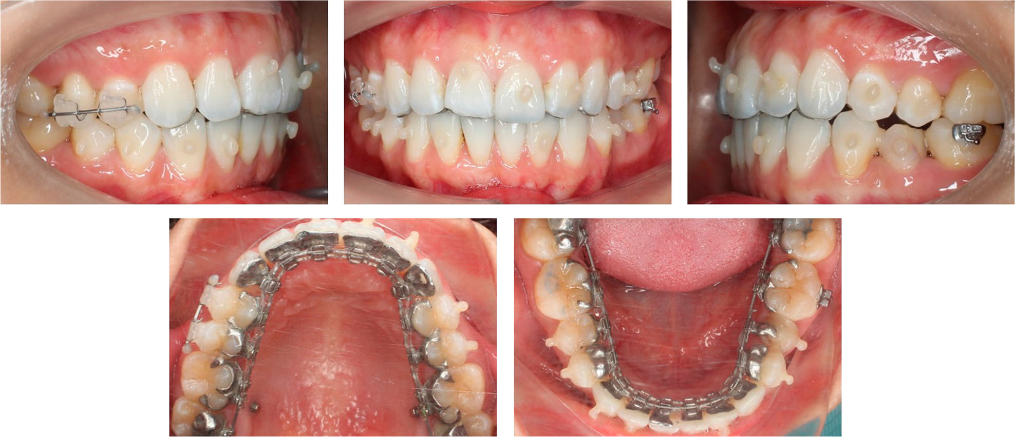
Figure 8.
Finishing stage with composite buttons for applying vertical settling elastics.
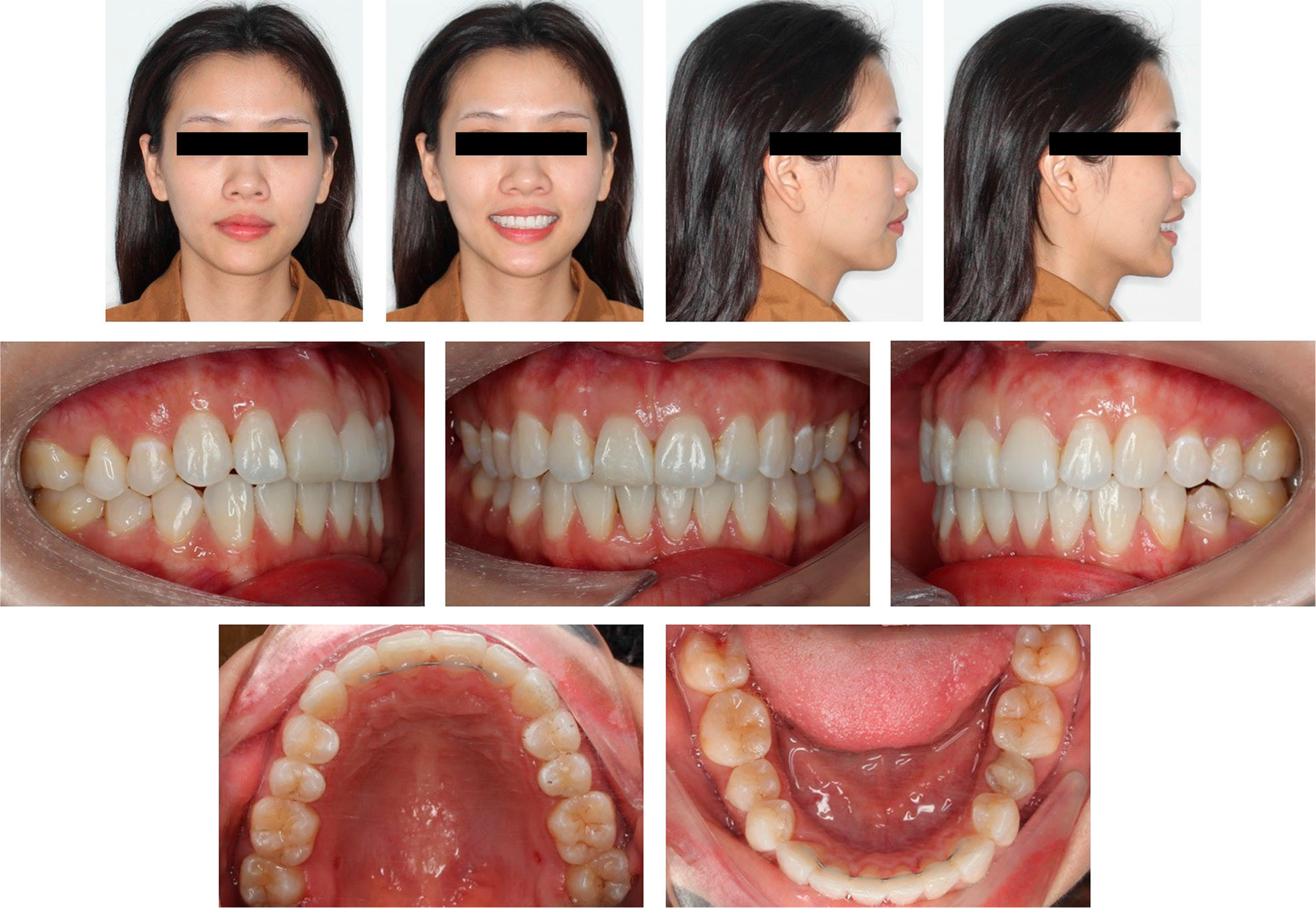
Figure 9.
Post-treatment facial and intraoral photographs.
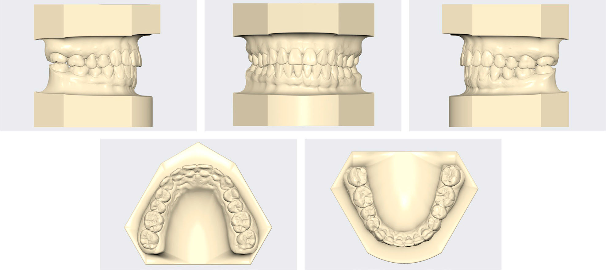
Figure 10.
Post-treatment models.
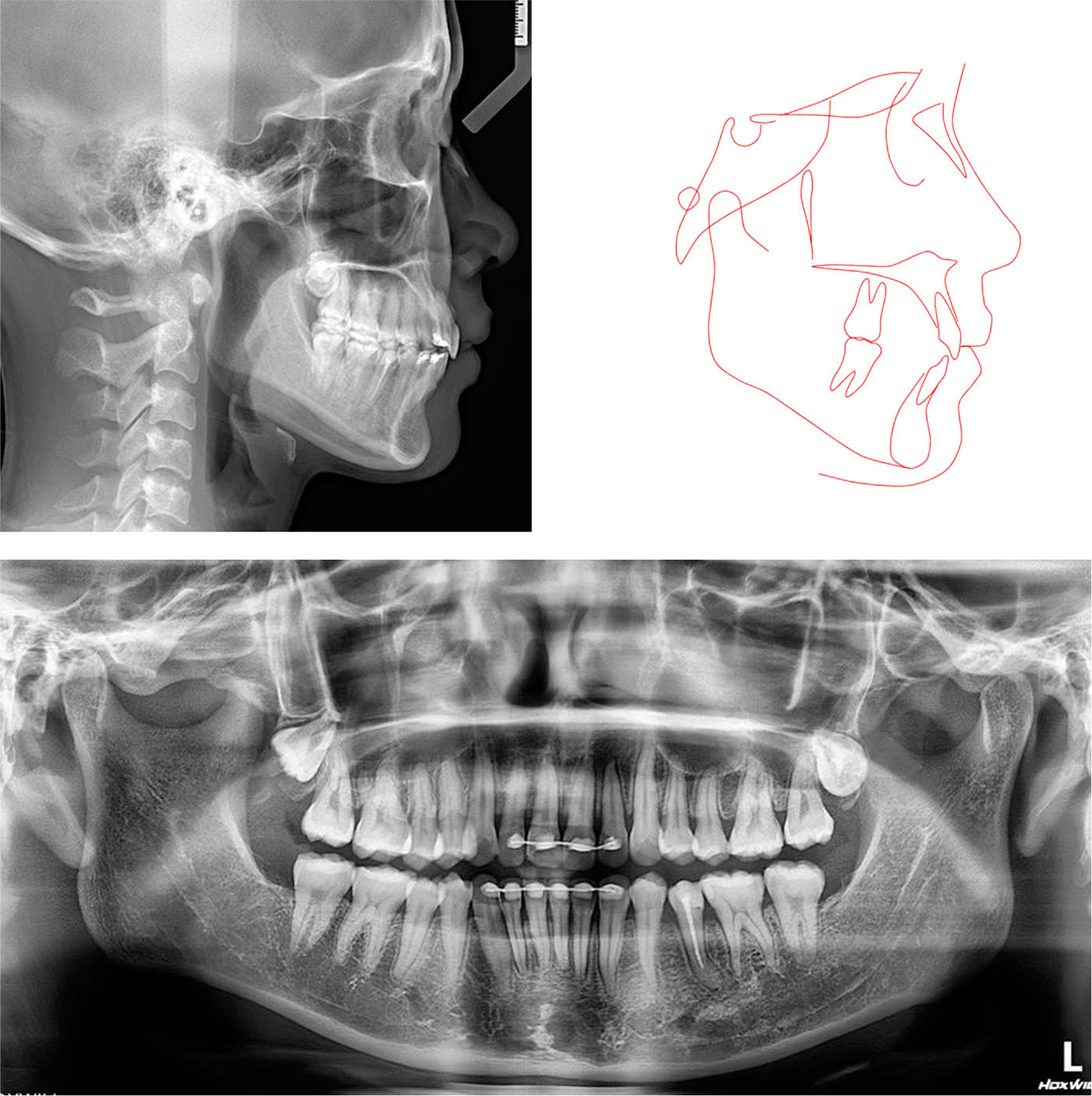
Figure 11.
Post-treatment radiographs and tracing.
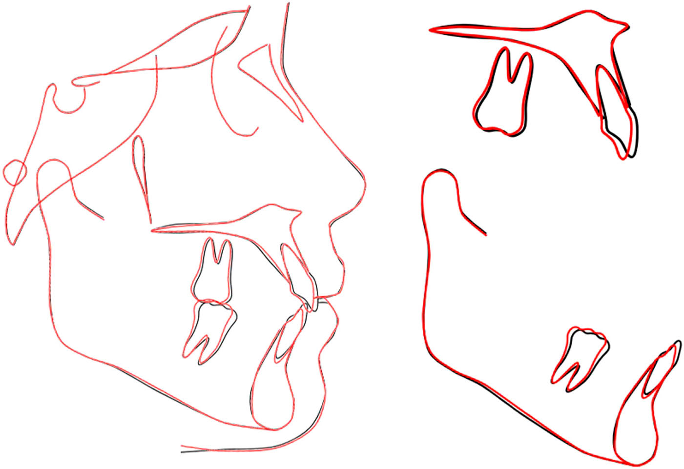
Figure 12.
Overall and regional cephalometric superimpositions of the initial (black) and final (red) lateral cephalometric tracings.
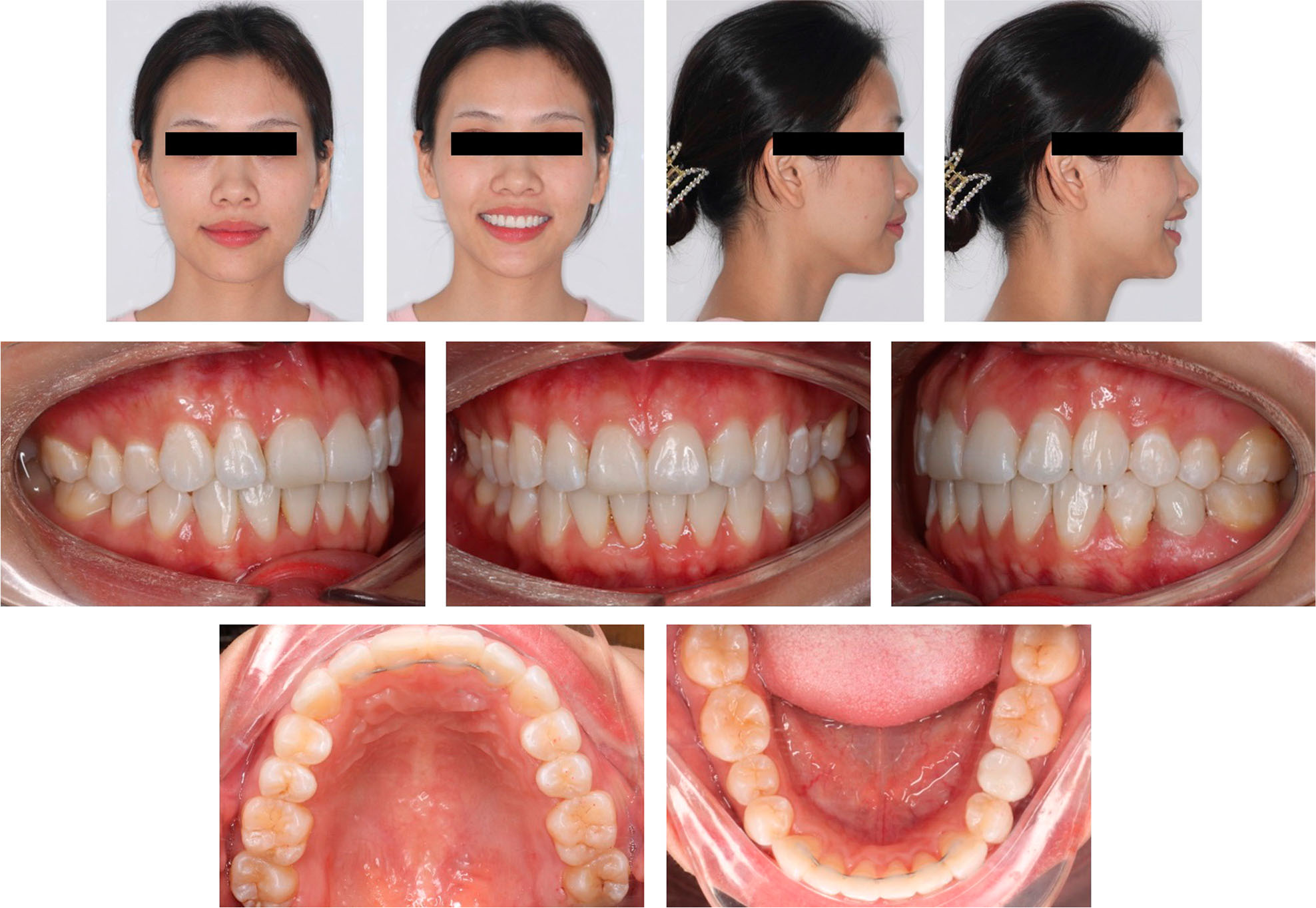
Figure 13.
One-year retention photographs.
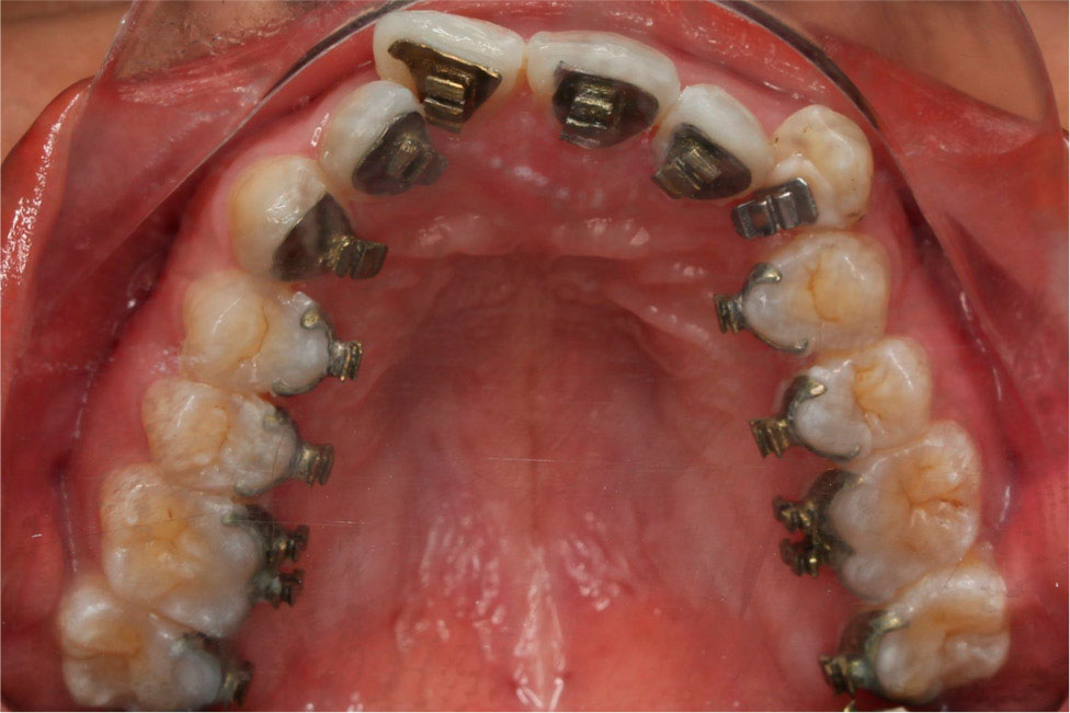
Figure 14.
Titanium bracket color variation by anodising.
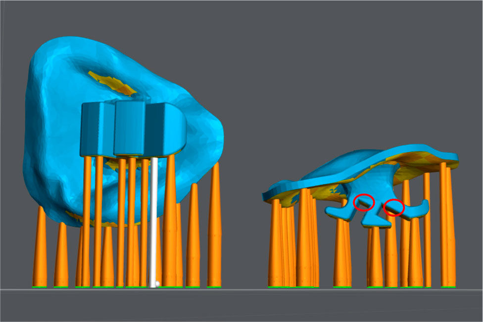
Figure 15.
Correct orientation of the bracket during 3D printing (left). Incorrect orientation leads to unsupported areas (red) which would be incorrectly printed (right).