
Tab. 1.
Chemical composition and minimum mechanical properties of S355J2C+N steel [20]
| Maximum element content, % | |||||
| C | Mn | Si | P | S | N |
| 0.22 | 1.5 | 0.55 | 0.035 | 0.035 | - |
| Minimal mechanical properties | |||||
| ReH MPa | Rm MPa | A % | |||
| 355 | 490 | 20 | |||
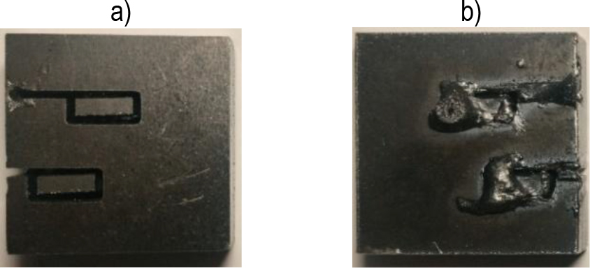
Fig. 1.
An attempt to cut out samples from S355J2C+N steel using the manufacturer's parameters: a) surface view, b) underside view
Tab. 2.
Cutting parameters used
| Steel S355J2C+N Laser Settings | |||||
|---|---|---|---|---|---|
| Focus [mm] | Speed [mm/s] | Peak Power [W] | Mount Rc | ||
| X1 | X2 | X3 | Y | Y’ | |
| 1 | 2 | 3 | 4 | 5 | 6 |
| 1 | 0.2 | 25.334 | 3600 | 45.82 | 45.65 |
| 2 | 0.2 | 25.334 | 4000 | 61.56 | 61.73 |
| 3 | 0.2 | 28 | 3600 | 55.01 | 55.18 |
| 4 | 0.2 | 28 | 4000 | 43.00 | 42.84 |
| 5 | 0.3 | 25.334 | 3600 | 58.41 | 58.58 |
| 6 | 0.3 | 25.334 | 4000 | 79.70 | 79.53 |
| 7 | 0.3 | 28 | 3600 | 42.88 | 42.71 |
| 8 | 0.3 | 28 | 4000 | 35.07 | 35.24 |
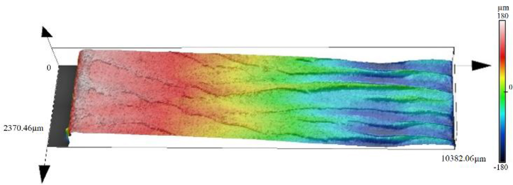
Fig. 2.
Example of surface topography obtained at the following settings: focal length 0.2 mm; feed rate 28 mm/s and peak power 3600 W (see Table 1 column 1, sample number 3)
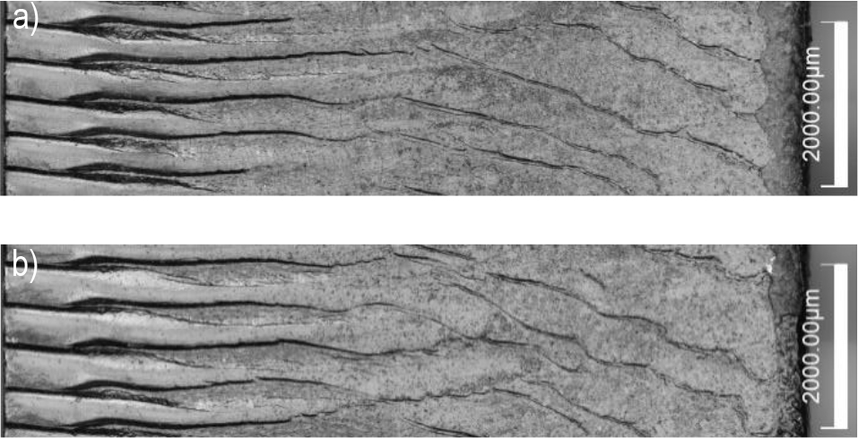
Fig. 3.
Photographs of the lateral surface of the cut specimen according to the parameters marked in Table 2, Column 1, as: a) Sample 1, b) Sample 2.
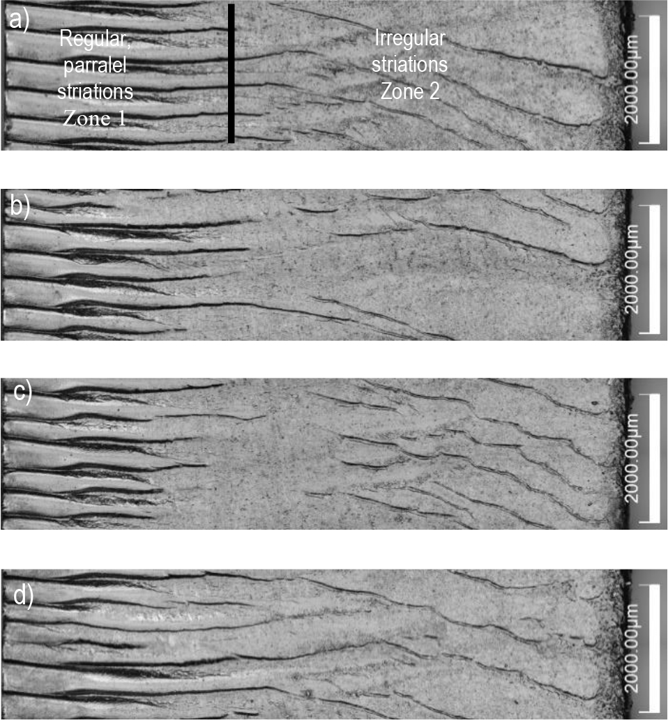
Fig. 4.
Photographs of the lateral surface of the cut specimen according to the parameters marked in Table 2, Column 1, as: a) Sample 5, b) Sample 6, c) Sample 7, d) Sample 8
Tab. 3.
Analysis of variance (ANOVA) results for the influence of cutting parameters on Rc
| Source 1 | DF 2 | Adj SS 3 | Adj MS 4 | F-Value 5 | P-Value 6 |
|---|---|---|---|---|---|
| Model | 6 | 1393.79 | 232.298 | 1039.10 | 0.024 |
| Linear | 3 | 655.54 | 218.513 | 977.44 | 0.024 |
| Focal length [mm] | 1 | 14.18 | 14.176 | 63.41 | 0.080 |
| Feed speed [mm/s] | 1 | 604.34 | 604.337 | 2703.27 | 0.012 |
| Peak power [W] | 1 | 37.03 | 37.026 | 165.62 | 0.049 |
| 2-Way Interaction | 3 | 738.25 | 246.083 | 1100.76 | 0.022 |
| Focal length [mm]* Feed speed [mm/s] | 1 | 322.51 | 322.512 | 1442.64 | 0.017 |
| Focal length [mm]*Peak power [W] | 1 | 11.87 | 11.868 | 53.09 | 0.087 |
| Feed speed [mm/s]*Peak power [W] | 1 | 403.87 | 403.867 | 1806.55 | 0.015 |
| Error | 1 | 0.22 | 0.224 | ||
| Total | 7 | 1394.01 |
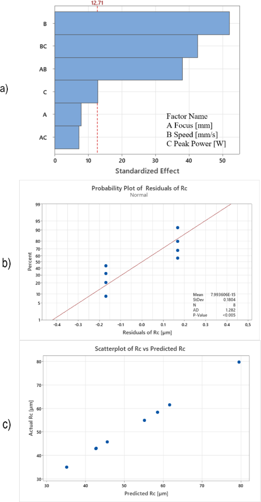
Fig. 5.
Pareto chart and diagnostic plots of the EPS production model.(a) Pareto chart of standardized effects, (b) Normal probability plot of residuals, (c) Predicted vs actual values.
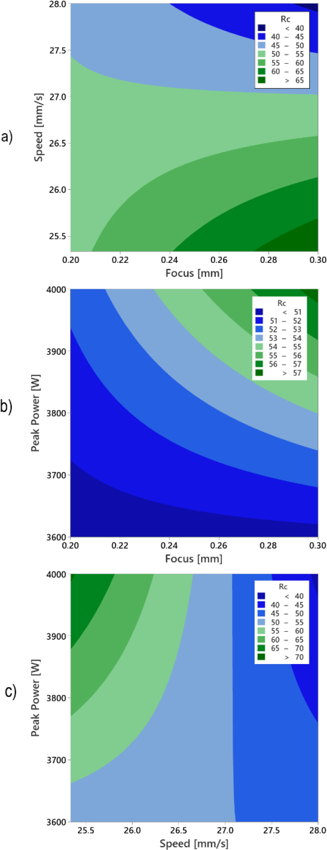
Fig. 6.
Influence of control factors on surface roughness Rc: a) Feed and focal speed; (b) Peak and focal power; (c) Peak power and feed speed
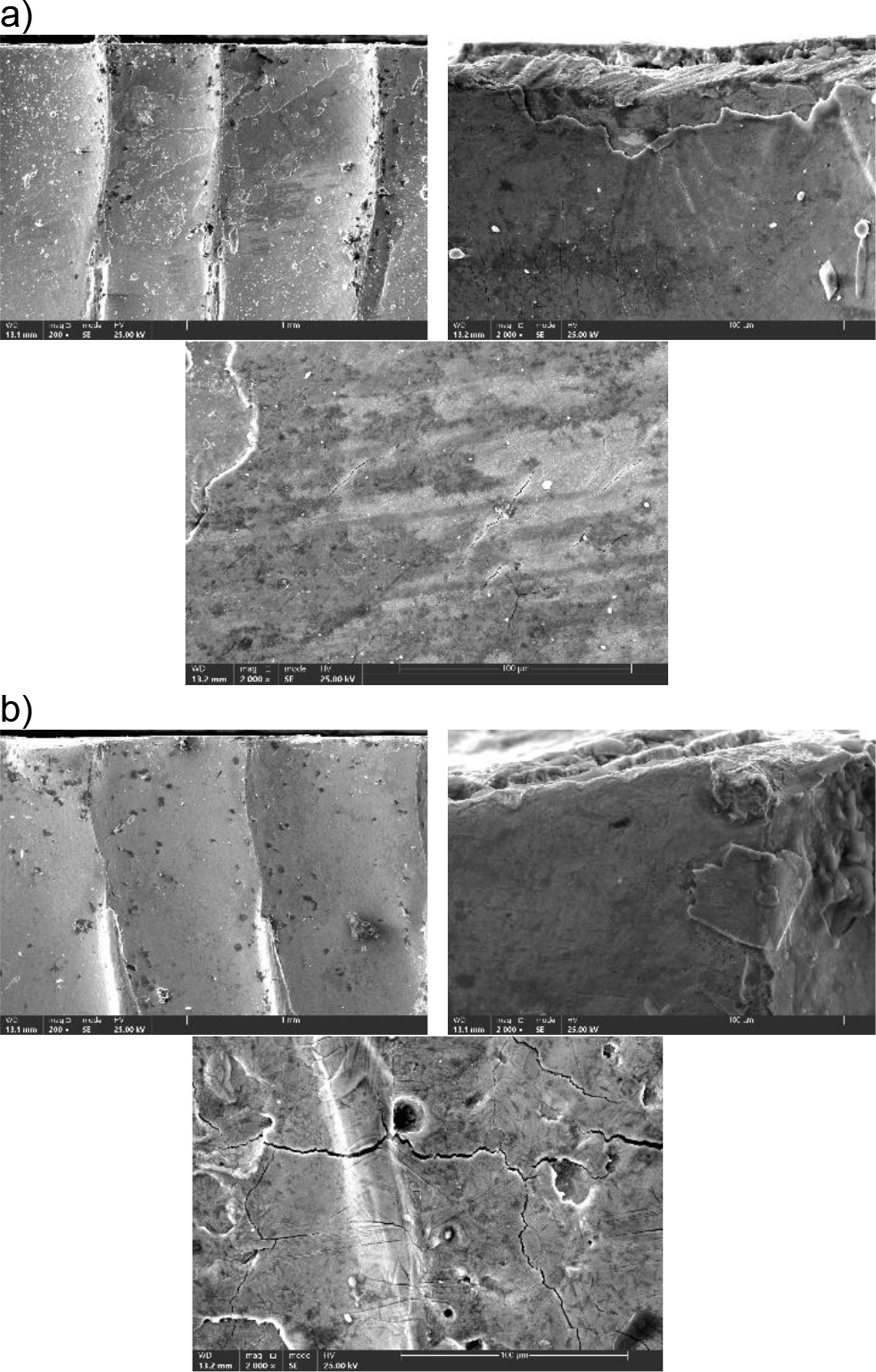
Fig. 7.
SEM photographs of the upper part of the cut surface. with visible cracks in the material, a) sample number 8; b) sample number 6 (see table 1)
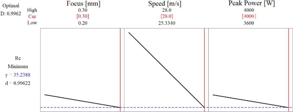
Fig. 8.
Response Optimizer ramp chart for Rc: optimal settings focus = 0.30 mm, speed = 28.0 mm/s, peak power = 4000 W; predicted minimum Rc = 35.24 μm with desirability D=0.996