
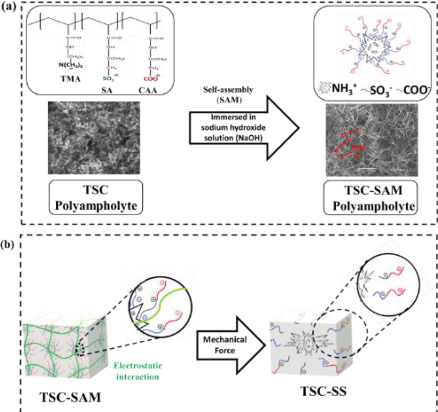
Scheme 1.
Schematic Diagram Illustration (a) Preparation of TSC Polyampholyte hydrogel (b) Preparation of TSC-SS Polyampholyte under mechanical force (uniaxial stress)
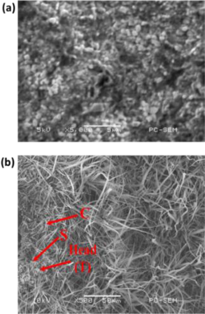
Fig. 1.
Scanning electron microscopy (SEM) images of TSC polyampholyte hydrogel (a) before and (b) after self-assembly process
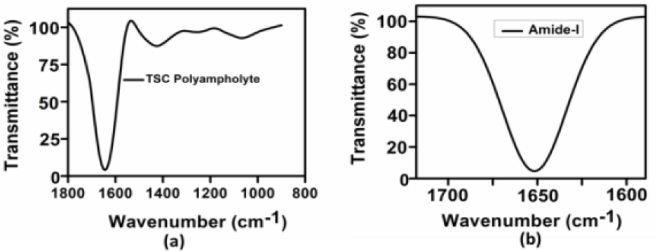
Fig. 2.
Characterization of TSC polyampholyte (a) IR spectra of the TSC Polyampholyte the representative of the IR absorbance spectra of the TSC Polyampholyte (b) The amide-I band region (~1600-1700 cm−1)
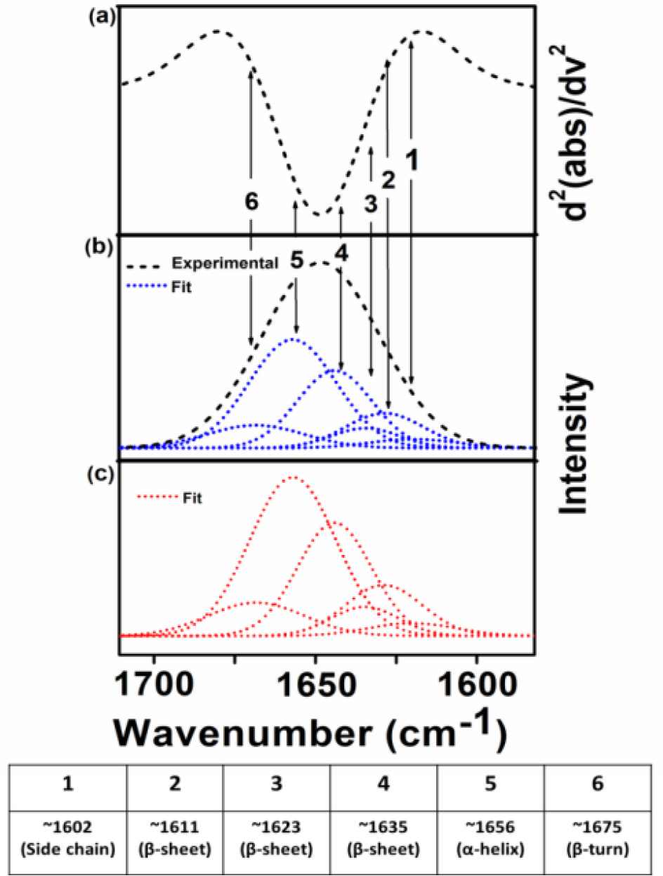
Fig. 3.
Spectra of protein secondary structure analysis (a) the IR absorbance spectra's second derivatives contained to the amide-I band (b) IR spectra in the amide-I were fitted by approximating the number and position, which experimental curve (▪▪▪) and simulated fits (---) (c) Result simulated fits are the six Gaussian band prof.
Tab. 1.
Amide-I number and position (cm−1) of TSC polyampholyte
| TSC polyampholyte | Amide-I number and position (cm−1) | |||||
|---|---|---|---|---|---|---|
| 1 | 2 | 3 | 4 | 5 | 6 | |
| T1S1C0 | ~1601 (Side chain) | ~1602 (Side chain) | ~1617 (β-sheet) | ~1633 (β-sheet) | ~1651 (α-helix) | ~1664 (β-turn) |
| T1S0.5C0.5 | ~1602 (Side chain) | ~1611 (β-sheet) | ~1623 (β-sheet) | ~1635 (β-sheet) | ~1656 (α-helix) | ~1675 (β-turn) |
| T1S0C1 | ~1602 (Side chain) | ~1619 (Side chain) | ~1631 (β-sheet) | ~1650 (α-helix) | ~1665 (β-turn) | ~1680 (β-turn) |
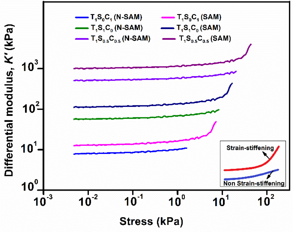
Fig. 4.
Strain-stiffening curves of TSC polyampholyte
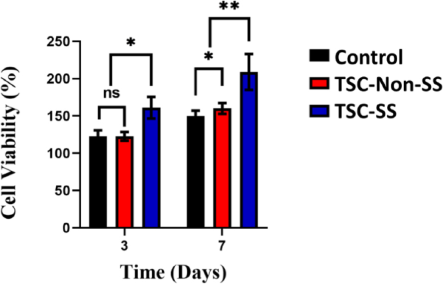
Fig. 5.
The cell viability of HDF-a of the different culture plate (control), TSC-Non-SS polyampholyte and TSC-SS polyampholyte
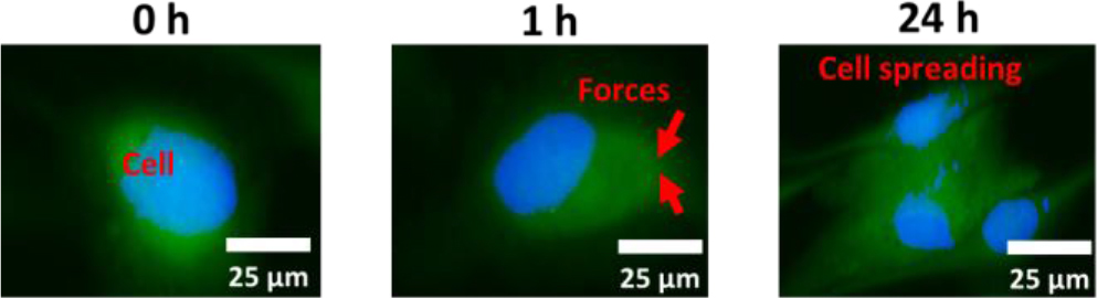
Fig. 6.
The HDF-a cells spreading on strain-stiffening of TSC polyampholyte. Scale bar 25 μm
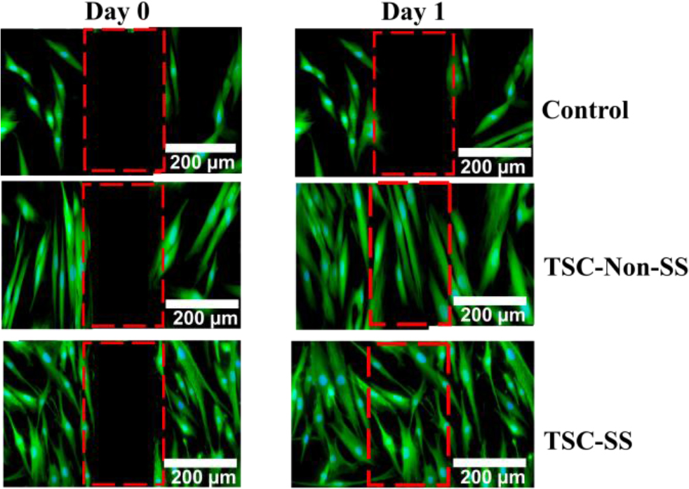
Fig. 7.
In vitro cell culture, strain-stiffening polyampholyte (TSC-SS), nonstrain-stiffening polyampholyte (TSC-Non-SS) and control induce motility in HDF-a cells after 1 day. Scale bar = 200 μm
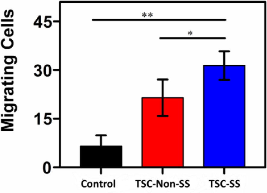
Fig. 8.
Cell migration quantification of TSC polyampholyte