
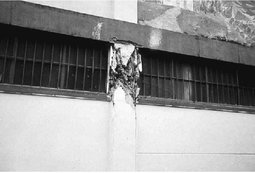
Figure 1
Short column failure due to partial infill wall, the 1999 Colombia earthquake [5].
Source: Guevara and Garcia
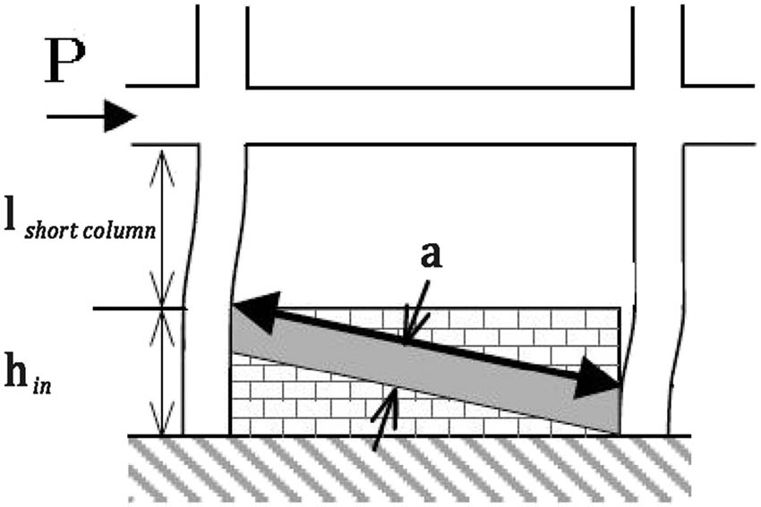
Figure 2
Equivalent strut of partial infill wall.
Source: Authors’ contribution.
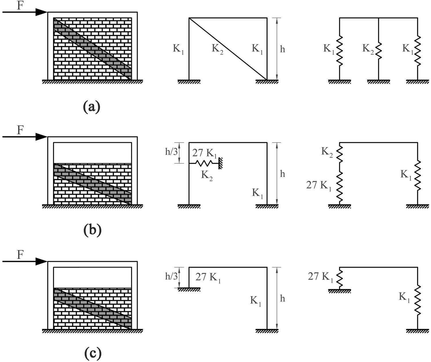
Figure 3
The total stiffness of infilled frame in three cases: (a) fully infilled frame, (b) partially infilled frame, and (c) partially infilled frame with a rigid wall.
Source: Authors’ contribution.
Table 1
Concrete and reinforcing rebar properties [23]
| Weight per unit volume (kg/m3) | Modulus of elasticity (N/mm2) | Poisson’s ratio (–) | Coefficient of thermal expansion (1/°c) | f′c Concrete compressive strength (N/mm2) | fy Bending reinforcement yield stress (N/mm2) | fys Shear reinforcement yield stress (N/mm2) |
|---|---|---|---|---|---|---|
| 2,500 | 24,516 | 0.15 | 1 × 10⁻⁵ | 24.5 | 392 | 392 |
Source: Noorifard et al.

Figure 4
The effect of mesh size of infill wall with shell element on the shear distribution (models were analyzed in ETABS software): (a) 10 cm mesh, (b) 20 cm mesh, and (c) 50 cm mesh.
Source: Authors’ contribution.
Table 2
Maximum shear in the right column and stiffness of partially infilled frame with different mesh sizes of infill wall with shell element (models were analyzed in ETABS software)
| Mesh size | Maximum shear in the right column (kN) | Stiffness (kN/m) |
|---|---|---|
| 50 cm | 158.6 | 68,680 |
| 20 cm | 156.5 | 65,120 |
| 10 cm | 156.1 | 64,410 |
Source: Authors’ contribution.
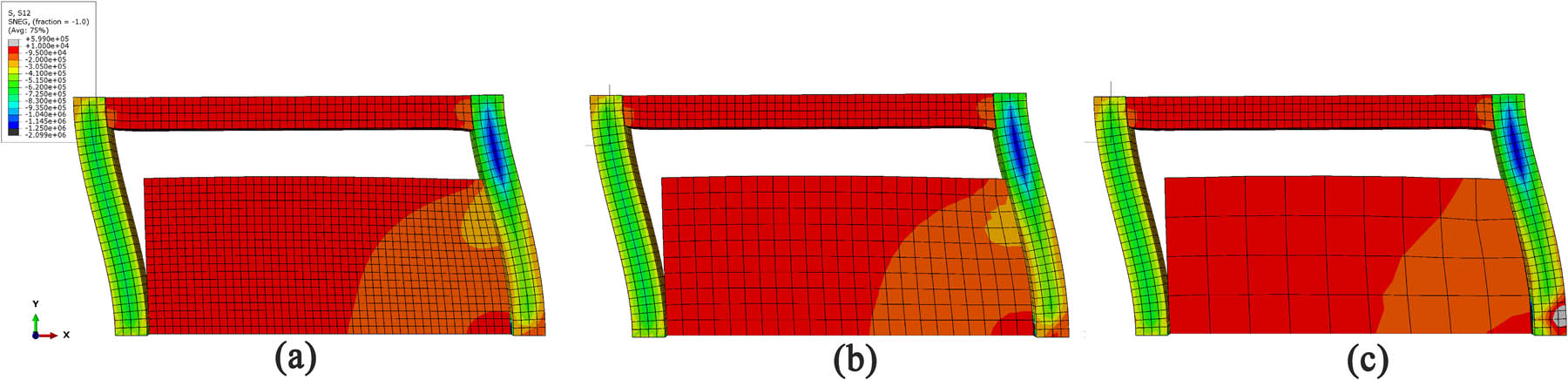
Figure 5
The effect of mesh size of infill wall with shell element on the stress distribution (models were analyzed in ABAQUS software): (a) 10 cm mesh, (b) 20 cm mesh, and (c) 50 cm mesh.
Source: Authors’ contribution.
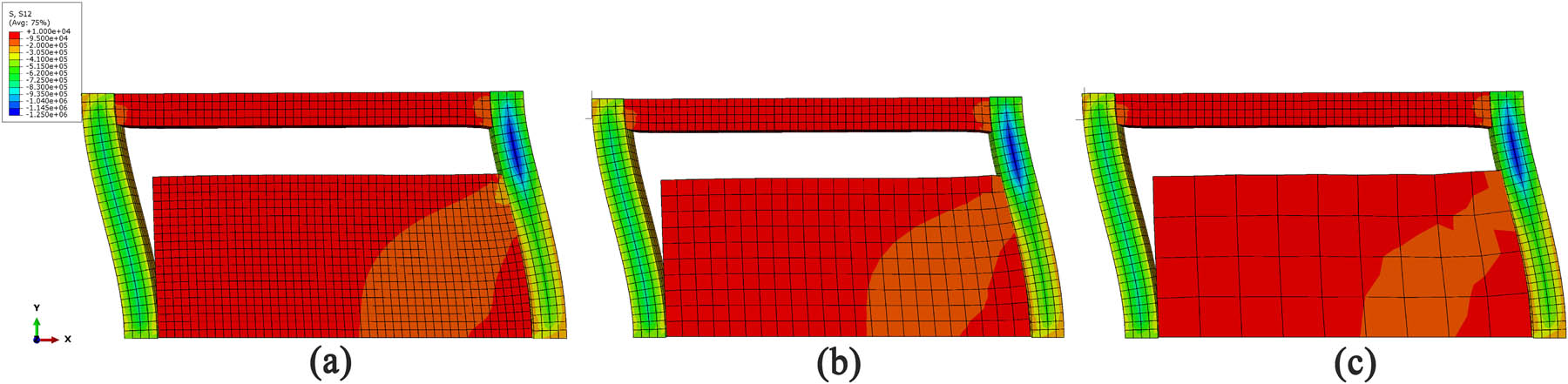
Figure 6
The effect of mesh size of infill wall with solid element on the stress distribution (models were analyzed in ABAQUS software): (a) 10 cm mesh, (b) 20 cm mesh, and (c) 50 cm mesh.
Source: Authors’ contribution.
Table 3
Shear in the right column and stiffness of partially infilled frame with different mesh sizes of shell and solid element of infill wall (models were analyzed in ABAQUS software)
| Element type | Mesh size (cm) | Shear in the right column (kN) | Stiffness (kN/m) | ||||||
|---|---|---|---|---|---|---|---|---|---|
| Point 1 | Point 2 | Point 3 | Point 4 | Point 5 | Average of 5 points | Average of 3 midpoints | |||
| Shell | 50 | 85.5 | 141.9 | 198.0 | 141.2 | 84.8 | 130.3 | 160.3 | 60,610 |
| Solid | 50 | 81.5 | 135.8 | 191.3 | 138.2 | 84.0 | 126.2 | 155.1 | 54,050 |
| Shell | 20 | 84.6 | 140.0 | 194.9 | 139.1 | 83.7 | 128.5 | 158.0 | 58,820 |
| Solid | 20 | 81.9 | 136.6 | 192.5 | 139.0 | 84.4 | 126.9 | 156.1 | 55,560 |
| Shell | 10 | 84.4 | 140.0 | 195.5 | 139.9 | 84.3 | 128.8 | 158.5 | 58,820 |
| Solid | 10 | 84.9 | 140.0 | 193.9 | 137.6 | 82.5 | 127.8 | 157.2 | 55,560 |
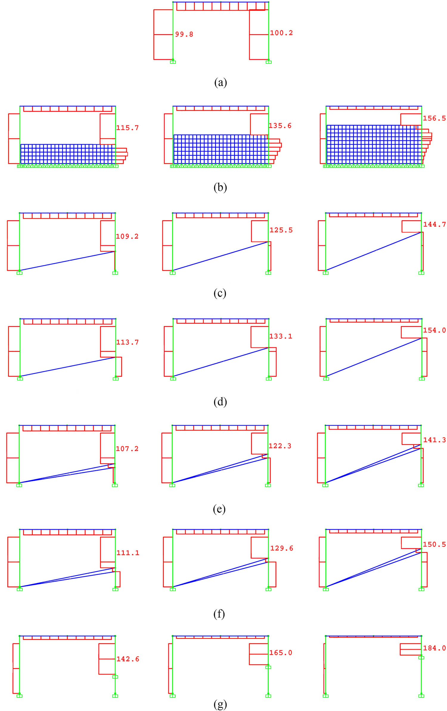
Figure 7
Six methods for modeling partially infilled frame and shear force diagram of a one-story, one-bay partially infilled frame with wall heights of 1/3, 1/2, and 2/3 of the frame height under the same force: (a) bare frame, (b) finite element, (c) New Zealand equivalent strut, (d) 0.2 d equivalent strut, (e) two struts with half of the width of New Zealand equivalent strut, (f) two struts with half of the width of 0.2 d equivalent strut, and (g) fixed support at the bottom of short column.
Source: Authors’ contribution.
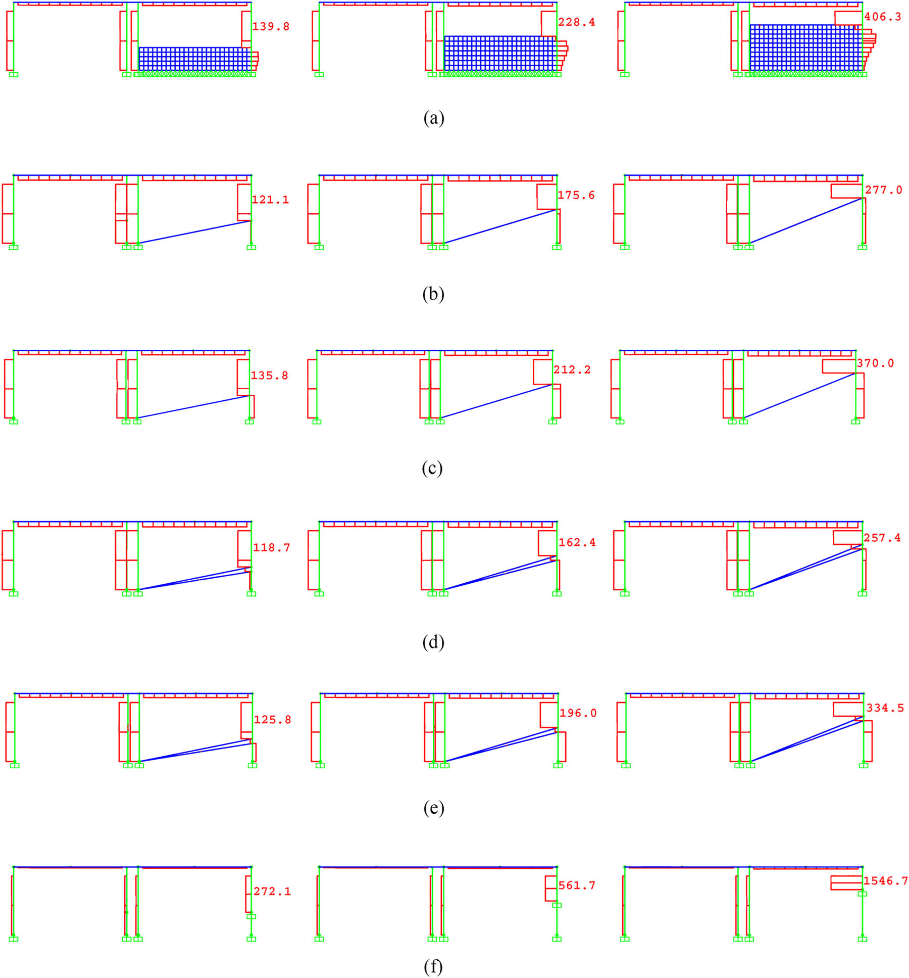
Figure 8
Six methods for modeling partially infilled frame and shear force diagram of a one-story, one-bay partially infilled frame with wall heights of 1/3, 1/2, and 2/3 of the frame height under the same displacement: (a) finite element, (b) New Zealand equivalent strut, (c) 0.2 d equivalent strut, (d) two struts with half of the width of New Zealand equivalent strut, (e) two struts with half of the width of 0.2 d equivalent strut, and (f) fixed support at the bottom of short column.
Source: Authors’ contribution.
Table 4
Six methods for modeling partially infilled frame and calculation of stiffness and shear force of a one-story, one-bay partially infilled frame with wall heights of 1/3, 1/2, and 2/3 of the frame height under the same force and the same displacement
| Stiffness | Shear in the right column under the same force | Shear in the right column under the same displacement | |||||||
|---|---|---|---|---|---|---|---|---|---|
| Ux (mm) | Kx (kN/m) | Infilled frame to bare frame (–) | Infilled frame (kN) | Infilled frame to bare frame (–) | Infilled frame (kN) | Bare frame (kN) | Infilled frame to bare frame (–) | ||
| Bare frame | 7.9 | 25,290 | — | 100 | — | — | — | — | |
| Partially infilled frame with wall height of 1/3 of the frame height | Finite element | 6.5 | 30,740 | 1.2 | 115.7 | 1.16 | 139.8 | 99.3 | 1.41 |
| New Zealand equivalent strut | 7.1 | 28,220 | 1.1 | 109.2 | 1.09 | 121.1 | 99.3 | 1.22 | |
| 0.2 d equivalent strut | 6.7 | 29,920 | 1.2 | 113.7 | 1.14 | 135.8 | 100.8 | 1.35 | |
| Two struts with half of the width of New Zealand equivalent strut | 7.3 | 27,520 | 1.1 | 107.2 | 1.07 | 118.7 | 99.5 | 1.19 | |
| Two struts with half of the width of 0.2 d equivalent strut | 6.9 | 28,900 | 1.1 | 111.1 | 1.11 | 125.8 | 96.9 | 1.30 | |
| Fixed support at the bottom of short column | 4.1 | 48,230 | 1.9 | 142.6 | 1.43 | 272.1 | 99.5 | 2.73 | |
| Partially infilled frame with wall height of 1/2 of the frame height | Finite element | 4.8 | 41,800 | 1.7 | 135.6 | 1.36 | 228.4 | 101.8 | 2.24 |
| New Zealand equivalent strut | 5.7 | 35,260 | 1.4 | 125.5 | 1.26 | 175.6 | 100.3 | 1.75 | |
| 0.2 d equivalent strut | 5.0 | 39,970 | 1.6 | 133.1 | 1.33 | 212.2 | 100.8 | 2.11 | |
| Two struts with half of the width of New Zealand equivalent strut | 5.9 | 33,650 | 1.3 | 122.3 | 1.22 | 162.4 | 97.5 | 1.67 | |
| Two struts with half of the width of 0.2 d equivalent strut | 5.3 | 37,740 | 1.5 | 129.6 | 1.30 | 196.0 | 99.0 | 1.98 | |
| Fixed support at the bottom of short column | 2.3 | 85,660 | 3.4 | 165.0 | 1.65 | 561.7 | 99.9 | 5.62 | |
| Partially infilled frame With wall height of 2/3 of the frame height | Finite element | 3.1 | 65,120 | 2.6 | 156.5 | 1.57 | 406.3 | 107.0 | 3.80 |
| New Zealand equivalent strut | 4.1 | 48,930 | 1.9 | 144.7 | 1.45 | 277.0 | 98.8 | 2.80 | |
| 0.2 d equivalent strut | 3.3 | 60,710 | 2.4 | 154.0 | 1.54 | 370.0 | 100.0 | 3.70 | |
| Two struts with half of the width of New Zealand equivalent strut | 4.4 | 45,880 | 1.8 | 141.3 | 1.41 | 257.4 | 98.1 | 2.62 | |
| Two struts with half of the width of 0.2 d equivalent strut | 3.6 | 56,030 | 2.2 | 150.5 | 1.51 | 334.5 | 98.0 | 3.41 | |
| Fixed support at the bottom of short column | 0.9 | 212,220 | 8.4 | 184.0 | 1.84 | 1546.7 | 99.7 | 15.51 | |
Source: Authors’ contribution.
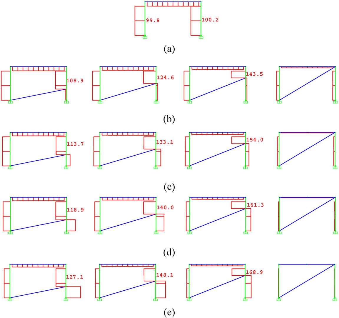
Figure 9
Shear force diagram of a one-story, one-bay partially infilled frame with wall heights of 1/3, 1/2, and 2/3 of the frame height, and fully infilled frame with different modulus of elasticity under the same force by using 0.2 d equivalent strut: (a) bare frame, (b) half of the original modulus of elasticity, (c) the original modulus of elasticity, (d) two times of the original modulus of elasticity, and (e) ten times of the original modulus of elasticity.
Source: Authors’ contribution.
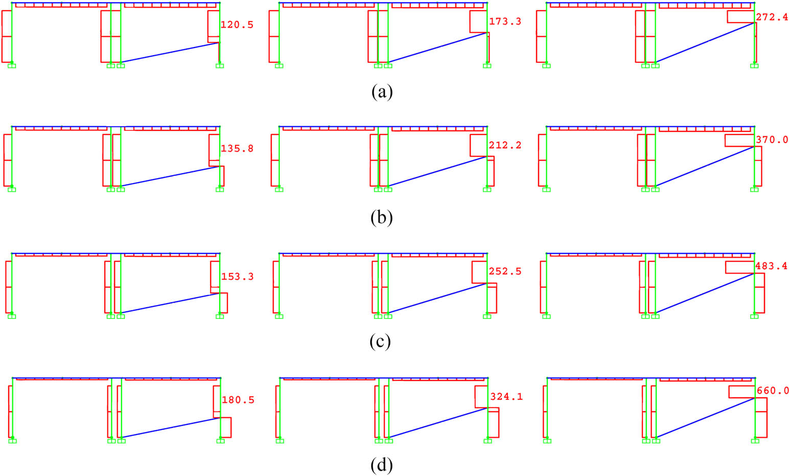
Figure 10
Shear force diagram of a one-story, one-bay partially infilled frame with wall heights of 1/3, 1/2, and 2/3 of the frame height with different modulus of elasticity under the same displacement by using 0.2 d equivalent strut: (a) half of the original modulus of elasticity, (b) the original modulus of elasticity, (c) two times of the original modulus of elasticity, and (d) ten times of the original modulus of elasticity.
Source: Authors’ contribution.
Table 5
Calculation of stiffness and shear force of a one-story one-bay partially infilled frame with heights of 1/3, ½, and 2/3, and fully infilled frame with different modulus of elasticity under the same force and the same displacement by using 0.2 d equivalent strut
| Stiffness | Shear in the right column under the same force | Shear in the right column under the same displacement | |||||||
|---|---|---|---|---|---|---|---|---|---|
| Ux (Mm) | Kx (kN/m) | Infilled frame to bare frame (–) | Infilled frame (kN) | Infilled frame to bare frame (–) | Infilled frame (kN) | Bare frame (kN) | Infilled frame to bare frame (–) | ||
| Bare frame | 7.9 | 25,290 | — | 100 | — | — | — | — | |
| Partially infilled frame with wall height of 1/3 of the frame height | 0.5E | 7.1 | 28,090 | 1.1 | 108.9 | 1.09 | 120.5 | 99.5 | 1.21 |
| E | 6.7 | 29,920 | 1.2 | 113.7 | 1.14 | 135.8 | 100.8 | 1.35 | |
| 2E | 6.2 | 32,170 | 1.3 | 118.9 | 1.19 | 153.3 | 101.3 | 1.51 | |
| 10E | 5.5 | 36,550 | 1.4 | 127.1 | 1.27 | 180.5 | 98.2 | 1.84 | |
| Partially infilled frame with wall height of 1/2 of the frame height | 0.5E | 5.8 | 34,750 | 1.4 | 124.6 | 1.25 | 173.3 | 101.1 | 1.71 |
| E | 5.0 | 39,970 | 1.6 | 133.1 | 1.33 | 212.2 | 100.8 | 2.11 | |
| 2E | 4.4 | 45,560 | 1.8 | 140.0 | 1.40 | 252.5 | 100.0 | 2.53 | |
| 10E | 3.7 | 54,430 | 2.2 | 148.1 | 1.48 | 324.1 | 101.5 | 3.19 | |
| Partially infilled frame with wall height of 2/3 of the frame height | 0.5E | 4.2 | 47,730 | 1.9 | 143.5 | 1.44 | 272.4 | 100.4 | 2.71 |
| E | 3.3 | 60,710 | 2.4 | 154.0 | 1.54 | 370.0 | 100.0 | 3.70 | |
| 2E | 2.7 | 75,120 | 3.0 | 161.3 | 1.61 | 483.4 | 100.7 | 4.80 | |
| 10E | 2.0 | 99,160 | 3.9 | 168.9 | 1.69 | 660.0 | 99.5 | 6.63 | |
| Fully infilled frame | 0.5E | 2.1 | 93,310 | 3.7 | — | — | — | — | — |
| E | 1.3 | 158,840 | 6.3 | — | — | — | — | — | |
| 2E | 0.7 | 283,050 | 11.2 | — | — | — | — | — | |
| 10E | 0.2 | 1,032,520 | 40.8 | — | — | — | — | — | |
Source: Authors’ contribution.
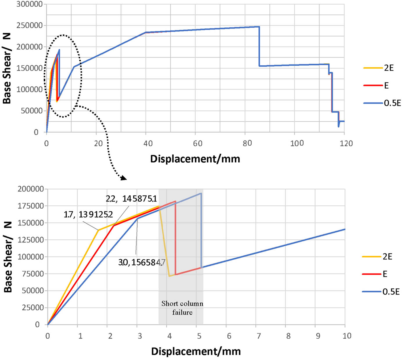
Figure 11
The pushover curves of three partially infilled frames with wall heights of 2/3 of the frame height with three different modulus of elasticity of infill wall.
Source: Authors’ contribution.
Table 6
Initial stiffness, ultimate strength, and lateral displacement in short column failure of three partially infilled frames with wall heights of 2/3 of the frame height with three different modulus of elasticity of infill wall
| Initial stiffness (kN/m) | Ultimate strength (kN) | Lateral displacement in short column failure (mm) | |
|---|---|---|---|
| 0.5E | 521,950 | 247.49 | 5.2 |
| E | 663,070 | 247.49 | 4.3 |
| 2E | 818,380 | 247.49 | 3.8 |
Source: Authors’ contribution.
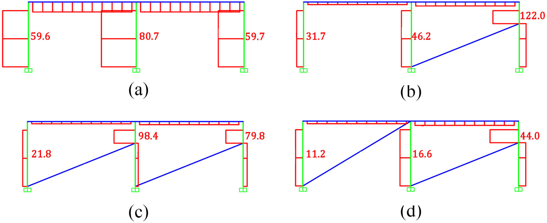
Figure 12
Shear force diagram of a one-story, two-bay frame under the same force by using 0.2 d equivalent strut: (a) two bare frames, (b) one partially infilled frame, one bare frame, (c) two partially infilled frames, (d) one partially infilled frame, one fully infilled frame.
Source: Authors’ contribution.
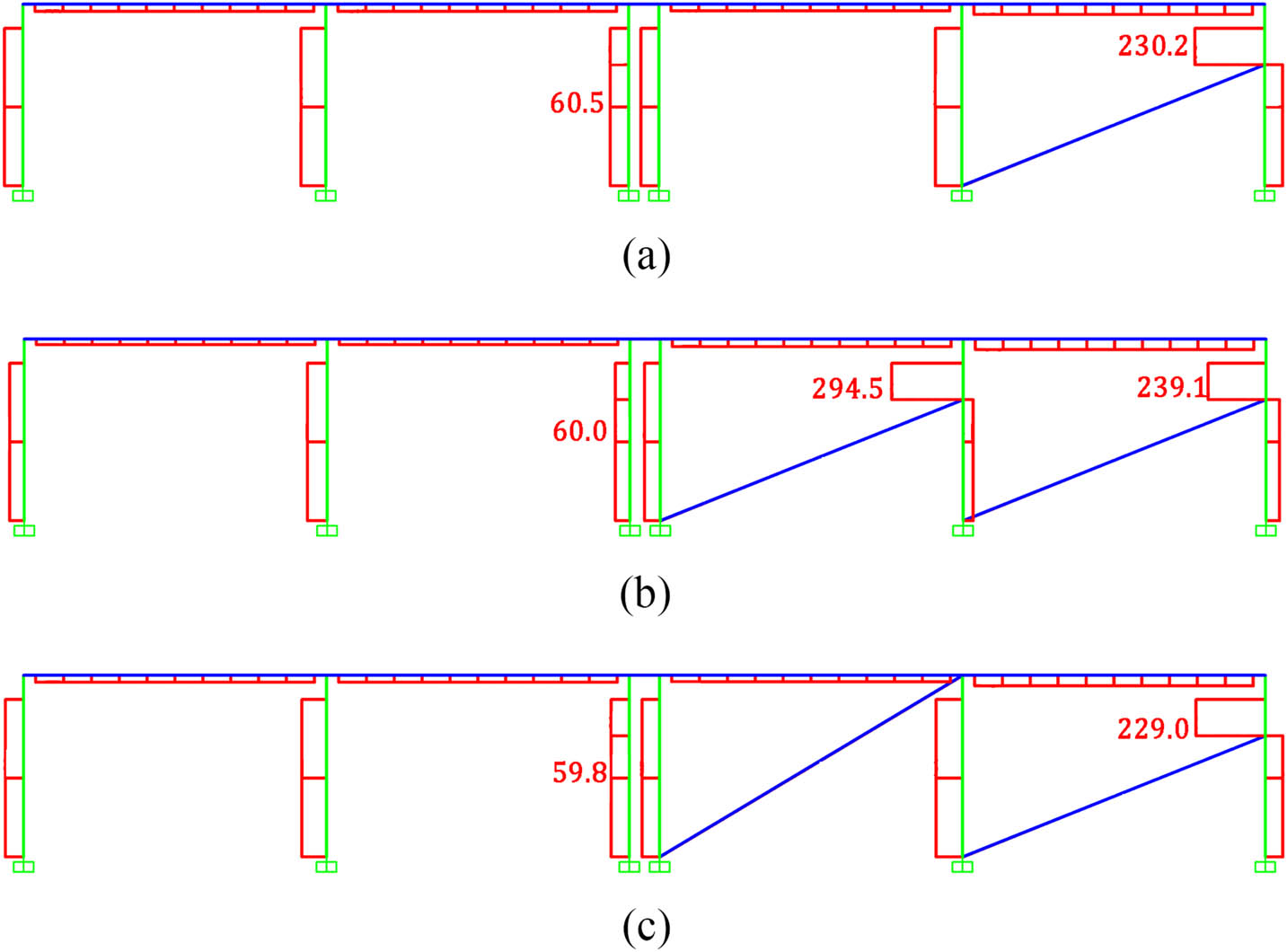
Figure 13
Shear force diagram of a one-story, two-bay frame under the same displacement by using 0.2 d equivalent strut: (a) one partially infilled frame, one bare frame, (b) two partially infilled frames, (c) one partially infilled frame, one fully infilled frame.
Source: Authors’ contribution.
Table 7
Calculation of stiffness and shear force of a one-story, two-bay partially infilled frame with different conditions of adjacent frame under the same force and the same displacement by using 0.2 d equivalent strut,
| Stiffness | Shear in the right column under the same force | Shear in the right column under the same displacement | ||||||
|---|---|---|---|---|---|---|---|---|
| Ux (mm) | Kx (kN/m) | Infilled frame to bare frame (–) | Infilled frame (kN) | Infilled frame to bare frame (–) | Infilled frame (kN) | Bare frame (kN) | Infilled frame to bare frame (–) | |
| Two bare frames | 4.9 | 40,510 | — | 59.7 | — | — | — | — |
| One partially infilled frame, one bare frame | 2.7 | 75,140 | 1.9 | 122.0 | 2.04 | 230.2 | 60.5 | 3.80 |
| Two partially infilled frames | 1.7 | 120,290 | 3.0 | 79.8 | 1.34 | 239.1 | 60.0 | 3.99 |
| One partially infilled frame, one fully infilled frame | 1.0 | 209,640 | 5.2 | 44.0 | 0.74 | 229.0 | 59.8 | 3.83 |
Source: Authors’ contribution.
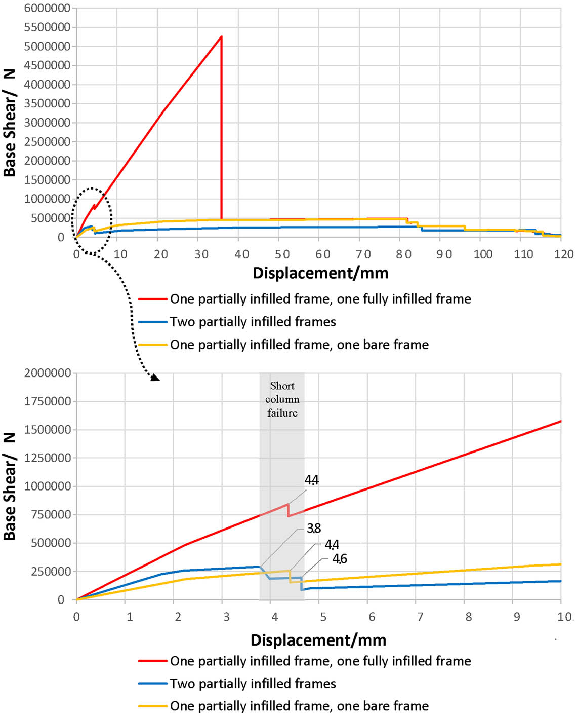
Figure 14
The pushover curves of three one-story, two-bay partially infilled frame with different conditions of adjacent frame.
Source: Authors’ contribution.
Table 8
Initial stiffness, ultimate strength, and lateral displacement in short column failure of three one-story, two-bay partially infilled frame with different conditions of adjacent frame
| Initial stiffness (kN/m) | Ultimate strength (kN) | Lateral displacement in short column failure (mm) | |
|---|---|---|---|
| One partially infilled frame, one bare frame | 81,080 | 472.70 | 04.4 |
| Two partially infilled frames | 130,170 | 272.15 | 3.8, 4.6 |
| 29.18 | |||
| One partially infilled frame, one fully infilled frame | 215,680 | 5257.64 | 4.4 |
Source: Authors’ contribution.
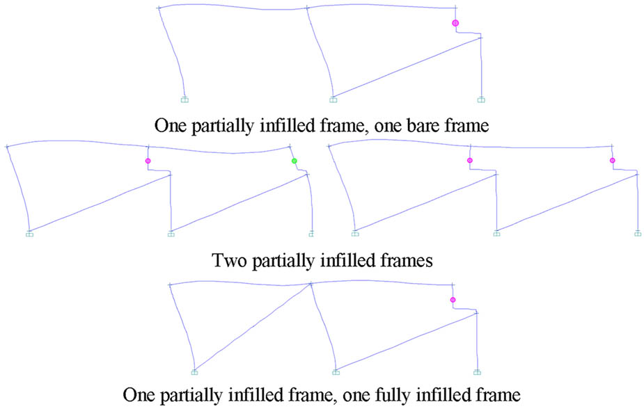
Figure 15
Formation of the plastic hinges in three one-story, two-bay partially infilled frame with different conditions of adjacent frame in the displacement range of 0.38–0.46 cm.
Source: Authors’ contribution.