
1. Introduction
Past earthquake events have shown that the presence of openings reduces the effect of infill walls on structural behavior [1], but these infilled frames generally have a better performance than bare frames under seismic load. However, when a frame is only partially infilled, the formation of a short-column mechanism may lead to adverse seismic performance [2,3] (Figure 1). A short column is formed when a portion of the column height is laterally restrained, resulting in the concentration of all deformation demands and stresses within the unrestrained segment. A common example occurs when infill walls do not extend over the full story height, leaving partial openings for windows or other architectural features [4]. Short column conditions are a major source of severe earthquake damage and typically arise from architectural design decisions [5]. In the following sections, some research related to the short column is reviewed.
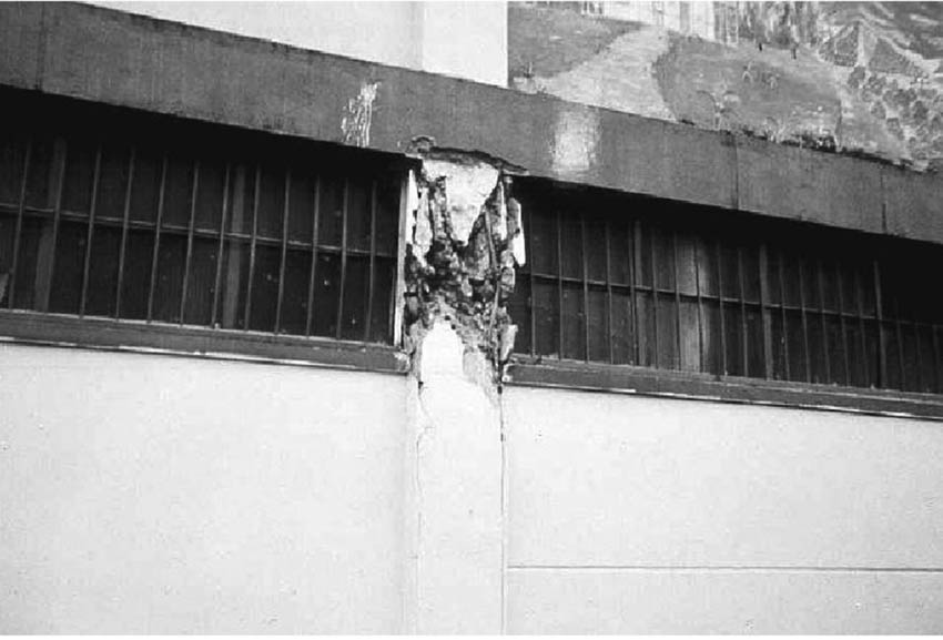
Figure 1
Short column failure due to partial infill wall, the 1999 Colombia earthquake [5].
Source: Guevara and Garcia
Since the conditions of short column originate primarily from architectural design of the building, Guevara and Garcia presented the architectural factors responsible for their formation and described their detrimental effect on the seismic performance of buildings in nontechnical language. In this article, examples of damage of short column in numerous earthquakes were presented, the architectural decisions leading to these damages were reviewed, and the structural explanation of the observed behavior was discussed. Finally, they proposed recommendations for mitigating this issue [5]. In a study conducted in 2011, Bikce examined the effects of parameters such as the width and height of the band window, the number of bays and stories, and the story height using time history analyses. The results indicated that, to reduce the short column effects, the width of the band windows should be less than 60% of the clear column spacing, while their height should exceed 35% of the clear story height [6]. The shear force generated at the points where infill walls terminate within a frame on the windward side can lead to failure of the adjacent column. Pradhan tried to identify the shear force values at such critical locations through analytical formula. In this article, various formulations of equivalent strut width proposed in the literature were compared with the established formula for verification, and subsequently used to evaluate shear forces at various locations in partially infilled frames. The equivalent strut width formulation can be used directly in structural analysis of both partially and fully infilled frames [2]. In 2018, Zhou et al. studied the effects of the infill walls and connections on structural behavior experimentally and analytically. Their results showed that the height of the infill, the type of connection between the infill and the frame, and the shear capacity ratio of the column to the infill significantly affect both the mechanical performance and failure mode. In the case of the infilled frame with rigid connection, as the height of the infill increases, the shear capacity decreases. In the case of the infilled frame with flexible connection, as the lateral restraint of the column is decreased, the risk of short column is decreased [7]. In 2020, Tabeshpour and Noorifard investigated all common types of windows used in architectural design, including central, eccentric, corner, and full length opening in the literature for reduction factor of equivalent strut of infill walls with opening. Due to the limited available research in some cases, both micro- and macro-models were employed. As a result, a comprehensive and practical algorithm based on the size and location of openings for modeling infilled frames with openings was proposed [1].
Several studies have proposed different strategies to mitigate the adverse effect of the short column. Cagatay et al. investigated an effective approach to prevent short-column failure by adding infill walls around the short column region. They conducted an analytical study on single-story infilled frames with one to five bays with different percentages of additional infill walls around the short column. In the following, a multistory building damaged due to the short column effect during the 1998 Adana-Ceyhan earthquake in Turkey was investigated. The results demonstrated that providing additional infill walls around the short column, the shear force is significantly reduced [8]. In 2011, Dogan studied the causes of short column and its influence on structural behavior under seismic loads. The study concluded that reducing stirrup spacing, controlling and limiting shear stress, and introducing elastic materials between column and infill walls are effective measures for minimizing short-column effects [9]. In 2012, Jayaguru and Subramanian presented the results of analytical and experimental investigations of a two-bay two-story RC frames with partial infill in the first story under lateral cyclic loading. The experimental findings indicated that the retrofitted frame with glass fiber reinforced polymer (GFRP) exhibits significantly higher ultimate strength and stiffness. The use of GFRP prevents the formation of captive-column conditions and so enhances the global performance of the partially infilled structure under seismic loads [10].
There are also several case studies on the short column phenomenon in the literature. Moon et al. evaluated the seismic performance of existing school buildings in Korea according to the procedure specified in ATC 63. They proposed analytical models to simulate the structural behavior of columns, infill walls, and their interaction. The accuracy of the proposed model was verified by comparing the analytical results with experimental test results for single-bay frames with and without infill walls containing openings. It was observed that columns may behave as short columns governed by shear action due to the presence of masonry infill walls with openings [11]. In 2016, Yadollahi et al. analyzed the effect of infill wall in formation of short column in a military aid watchtower in Turkey and compared the analysis result with the effect of earthquake that have been seen after earthquake [12]. In 2020, Duran et al. conducted both field investigations and analytical studies on adjacent buildings affected by the 2016 Turkey earthquake. A building with a basement story and full-length opening at the ground level was collapsed, whereas a neighboring building without a basement was not significantly damaged. Pushover analyses of both structures, modeled as infilled frames, showed that the primary cause of collapse was the increased shear demand associated with short-column effects [13].
Despite extensive studies on short columns, a macro-scale modeling approach suitable for engineering applications that accounts for variations in infill wall materials and heights and the conditions of adjacent frames has not yet been adequately developed. This study investigates different approaches for modeling short columns and examines the effects of three key parameters on short-column behavior at the macro scale: the height of the partial infill wall, the stiffness of the infill wall, and the conditions of adjacent frames. From a global perspective, it influences the distribution of stiffness throughout the structure, both in plan and along the building height. Accordingly, shear force and structural stiffness are considered the primary dependent variables in this study.
2. Equation for determining the width of the equivalent strut of short infill wall for estimating the stiffness of partially infilled frame
Some references and research have proposed a reduction factor for initial stiffness or ultimate strength of infilled frames with openings, these factors are typically expressed as functions of the ratio of the opening area to the infill wall area, or the opening length to the wall length [14–19]. However, the behavior of partially infilled frames differs from that of infilled frames containing conventional openings. According to the recommendations of NZSEE, FEMA 356, and Al-Chaar, the equation used to determine the equivalent strut width of a short infill wall, or an infill wall with a full-length opening, is similar to the equation of fully infill wall. The only modification involves the effective height of the infill wall; therefore, no opening reduction factor is required [14,15,20] (Figure 2) (Equations 1, 2).
where = diagonal length of infill wall, = column height between centrelines of beams, = height of infill wall, = modulus of elasticity of frame material, = modulus of elasticity of infill material, = moment of inertial of column, = thickness of infill wall, = angle of diagonal of wall, and = coefficient used to determine equivalent width of infill wall.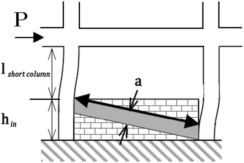
Figure 2
Equivalent strut of partial infill wall.
Source: Authors’ contribution.
By accepting a similar equation for the equivalent strut width in both fully and partially infill wall, simpler equations in the literature such as 0.2 times the infill wall diagonal [21,22] may also be used.
There is a fundamental difference between the macro-modeling of fully infilled and partially infilled frames. For simplicity, the beam is assumed to possess sufficiently high stiffness. In a fully infilled frame, the stiffness of infill wall and the surrounding frame can be modeled as parallel springs. However, in a partially infilled frame, the stiffness of infill wall acts in series with the windward column, and the resulting combined stiffness acts in parallel with the leeward column. For an extremely stiff infill wall, the short wall may be assumed to behave as a rigid element, causing the effective fixed support of the windward column to shift to the level immediately above the wall. In this case, the system becomes equivalent to two parallel springs, where the windward spring has a very high stiffness because of the rigid short infill wall (Figure 3). In equations (3)–(7), K t is the total stiffness of the infilled frame system, K 1 is the stiffness of the columns, and K 2 is the stiffness of the infill wall.
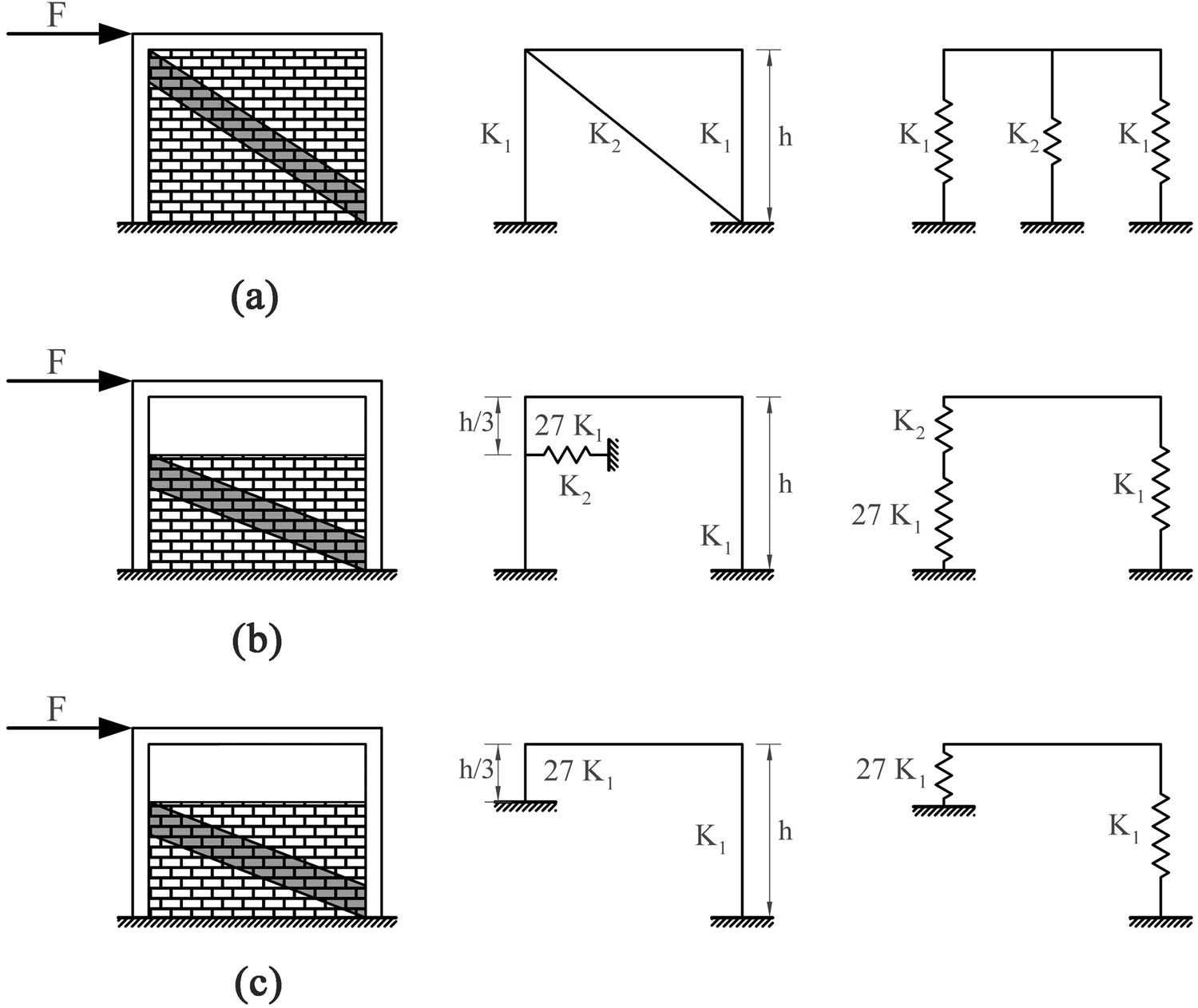
Figure 3
The total stiffness of infilled frame in three cases: (a) fully infilled frame, (b) partially infilled frame, and (c) partially infilled frame with a rigid wall.
Source: Authors’ contribution.
Stiffness of infill wall (equivalent compression strut):
Case a: Case b: Case c:3. Investigating different modeling methods for partially infilled frames and the effect of wall height on short column formation
In this section, different methods for modeling partially infilled frame are examined. The investigation was conducted on a one-story, one-bay reinforced concrete frame with a span length of 5 m and a story height of 3 m. The columns have a cross-sectional dimension of 40 cm × 40 cm, while the beam has a cross section of 30 cm × 40 cm. The column reinforcement consists of 4Φ10 stirrups at 25 cm spacing and 12Φ20 longitudinal reinforcing bars. The material properties of concrete and reinforcing bar are presented in Table 1. The modulus of elasticity of the masonry infill walls was assumed to be 4,800 MPa. The frames were analyzed under a lateral force of 200 kN applied from right to left by using ETABS software.
Table 1
Concrete and reinforcing rebar properties [23]
| Weight per unit volume (kg/m3) | Modulus of elasticity (N/mm2) | Poisson’s ratio (–) | Coefficient of thermal expansion (1/°c) | f′c Concrete compressive strength (N/mm2) | fy Bending reinforcement yield stress (N/mm2) | fys Shear reinforcement yield stress (N/mm2) |
|---|---|---|---|---|---|---|
| 2,500 | 24,516 | 0.15 | 1 × 10⁻⁵ | 24.5 | 392 | 392 |
Source: Noorifard et al.
3.1. Validation of finite element models
First, due to the importance of the finite element model, as a basis for comparison with other modeling approaches, a sensitivity analysis was conducted for mesh size of infill wall. Three partially infilled frames with mesh size of 10, 20, and 50 cm were modeled. In all models, infill walls were made with shell element. According to the shear force diagram in Figure 4 and the results of analysis presented in Table 2, the 20 cm mesh size provides an appropriate balance between modeling accuracy and computational efficiency. Therefore, a mesh size of 20 cm was adopted for the infill walls in all subsequent finite element analyses.

Figure 4
The effect of mesh size of infill wall with shell element on the shear distribution (models were analyzed in ETABS software): (a) 10 cm mesh, (b) 20 cm mesh, and (c) 50 cm mesh.
Source: Authors’ contribution.
Table 2
Maximum shear in the right column and stiffness of partially infilled frame with different mesh sizes of infill wall with shell element (models were analyzed in ETABS software)
| Mesh size | Maximum shear in the right column (kN) | Stiffness (kN/m) |
|---|---|---|
| 50 cm | 158.6 | 68,680 |
| 20 cm | 156.5 | 65,120 |
| 10 cm | 156.1 | 64,410 |
Source: Authors’ contribution.
For verifying the results of the finite element models developed in ETABS software, these models were analyzed by using another finite element software. For this purpose, ABAQUS software was selected. In ABAQUS models, the frame was modeled using solid elements. Since the mortar strength was assumed to be greater than that of the bricks, the infill wall was considered a homogeneous continuum and modeled using both shell and solid elements. The geometric dimensions and material properties were kept identical to those used in the ETABS models. In these models, the mesh type of frame and infill wall with solid element was hex and structured, and the mesh type of infill wall with shell element was quad and structured. In the models that infill wall was made with shell element; the windward column was connected to the infill wall through the shell to solid coupling constraint. In the models that infill wall was made with solid element, the interaction between infill and frame was defined by contact element, and a friction coefficient of 0.7 was assigned at the interface, allowing relative sliding between the frame and the infill wall while permitting separation under tensile stresses. The models are analyzed under a lateral force of 200 kN applied from right to left. Stress distributions of infilled frames are illustrated in Figures 5 and 6 for infill wall with shell element and solid element, respectively. These figures clearly demonstrate the formation of the equivalent diagonal compression strut within the infill wall. The shear force in the right column and the lateral stiffness of partially infilled frame for different mesh sizes of shell and solid element of infill wall are presented in Table 3. The results of analyses in both software and with two different element types of infill wall show that the shear force and stiffness of the models are within a similar range. Therefore, the finite element model developed in ETABS is considered sufficiently accurate and reliable for use as the reference model in the evaluation and comparison of the macro-modeling approaches.
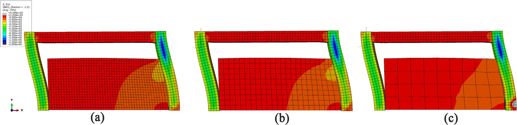
Figure 5
The effect of mesh size of infill wall with shell element on the stress distribution (models were analyzed in ABAQUS software): (a) 10 cm mesh, (b) 20 cm mesh, and (c) 50 cm mesh.
Source: Authors’ contribution.
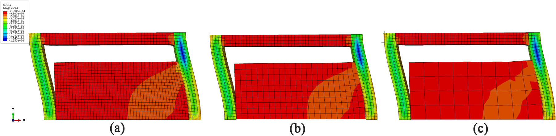
Figure 6
The effect of mesh size of infill wall with solid element on the stress distribution (models were analyzed in ABAQUS software): (a) 10 cm mesh, (b) 20 cm mesh, and (c) 50 cm mesh.
Source: Authors’ contribution.
Table 3
Shear in the right column and stiffness of partially infilled frame with different mesh sizes of shell and solid element of infill wall (models were analyzed in ABAQUS software)
| Element type | Mesh size (cm) | Shear in the right column (kN) | Stiffness (kN/m) | ||||||
|---|---|---|---|---|---|---|---|---|---|
| Point 1 | Point 2 | Point 3 | Point 4 | Point 5 | Average of 5 points | Average of 3 midpoints | |||
| Shell | 50 | 85.5 | 141.9 | 198.0 | 141.2 | 84.8 | 130.3 | 160.3 | 60,610 |
| Solid | 50 | 81.5 | 135.8 | 191.3 | 138.2 | 84.0 | 126.2 | 155.1 | 54,050 |
| Shell | 20 | 84.6 | 140.0 | 194.9 | 139.1 | 83.7 | 128.5 | 158.0 | 58,820 |
| Solid | 20 | 81.9 | 136.6 | 192.5 | 139.0 | 84.4 | 126.9 | 156.1 | 55,560 |
| Shell | 10 | 84.4 | 140.0 | 195.5 | 139.9 | 84.3 | 128.8 | 158.5 | 58,820 |
| Solid | 10 | 84.9 | 140.0 | 193.9 | 137.6 | 82.5 | 127.8 | 157.2 | 55,560 |
3.2. Six methods for modeling partially infilled frame
Six methods for modeling partially infilled frame are as follows. In this section, while studying different methods, by modeling infill walls with heights of 1/3, 1/2, 2/3 of the frame height simultaneously, the effect of wall height on formation of short column is also investigated.
Finite element: In this approach, the infill wall is modeled using shell elements, representing the actual behavior of the partially infilled frame. Due to the fact that infill wall is attached to the frame on windward side and it is separated from the frame on leeward side, this interaction is considered in modeling the infill wall with shell element in software.
New Zealand equivalent strut: According to NZSEE, FEMA 356, and Al-Chaar recommendations, equation for determining the strut width of infill wall in partially infilled frame is similar to the fully infilled frame.
0.2 d equivalent strut: This method is similar to the previous method; however, instead of using code-based formulations involving multiple parameters, the strut width is defined using a simplified expression available in the literature, taken as a fraction (0.2) of the infill wall diagonal length.
Two struts with half of the width of New Zealand equivalent strut: In the equivalent strut method, column rotation is not fully restrained at the contact region with the infill wall. To better capture the rotational behavior of the column adjacent to the top of short infill wall, two closely struts are introduced. In this method, each strut has half the area of the New Zealand equivalent strut.
Two struts with half of the width of 0.2 d equivalent strut: This method follows the same concept as the previous one, but each strut has half the area of 0.2 d equivalent strut.
Fixed support at the bottom of short column: This method represents the extreme case of short-column behavior by assuming a fully fixed boundary condition at the base of the short column region.
To study the behavior of short column by different methods of modeling, the systems were analyzed under a lateral force of 200 kN applied from right to left. The shear force diagram of partially infilled frame with wall heights of 1/3, 1/2, and 2/3 of the frame height under the same force and under the same displacement is demonstrated in Figures 7 and 8, respectively, while the corresponding numerical results are summarized in Table 4. The importance of studying the shear force in the same displacement is based on the philosophy of capacity-based design. For this purpose, a bare frame under a force of 200 kN in the left side is connected to the studied systems through a rigid link and the structure is analyzed. For investigating the failure of the reinforced concrete short column as a brittle failure, the main assessment tool is to control shear force in the same displacement. In reinforced concrete structures, long columns are typically designed based on seismic force demands, whereas short columns must be designed to resist forces corresponding to the capacity of long columns in order to ensure adequate ductility and prevent brittle shear failure.
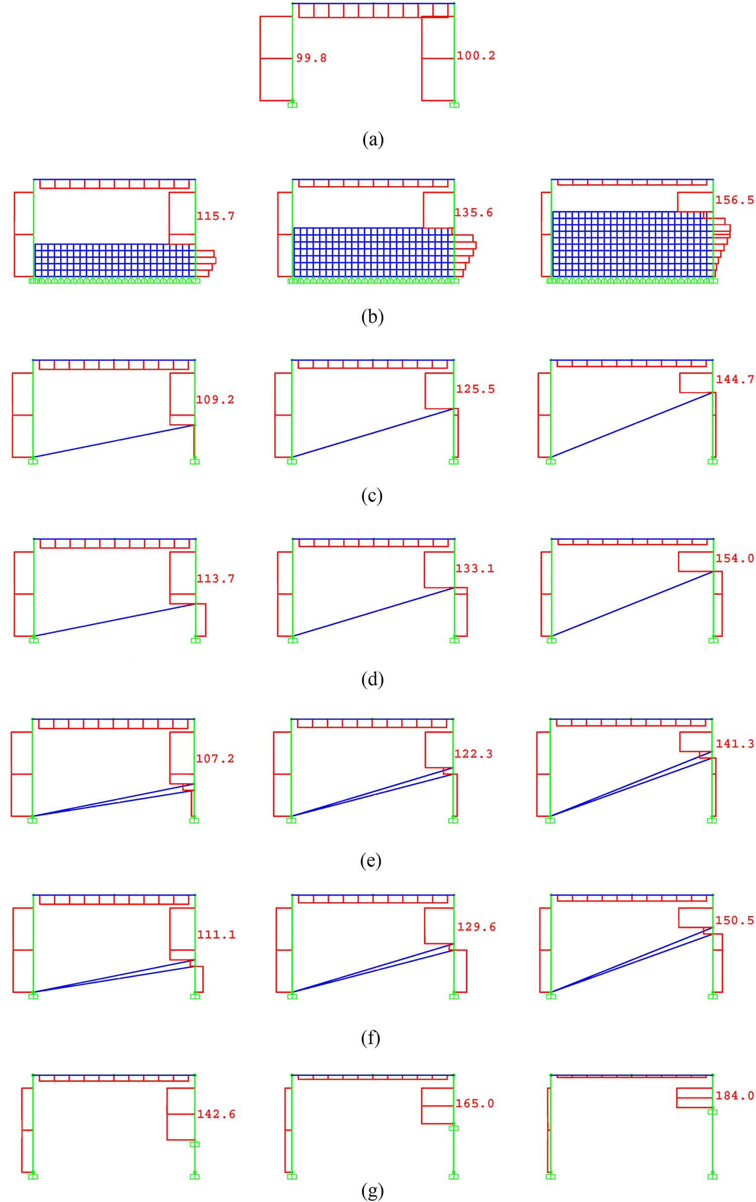
Figure 7
Six methods for modeling partially infilled frame and shear force diagram of a one-story, one-bay partially infilled frame with wall heights of 1/3, 1/2, and 2/3 of the frame height under the same force: (a) bare frame, (b) finite element, (c) New Zealand equivalent strut, (d) 0.2 d equivalent strut, (e) two struts with half of the width of New Zealand equivalent strut, (f) two struts with half of the width of 0.2 d equivalent strut, and (g) fixed support at the bottom of short column.
Source: Authors’ contribution.
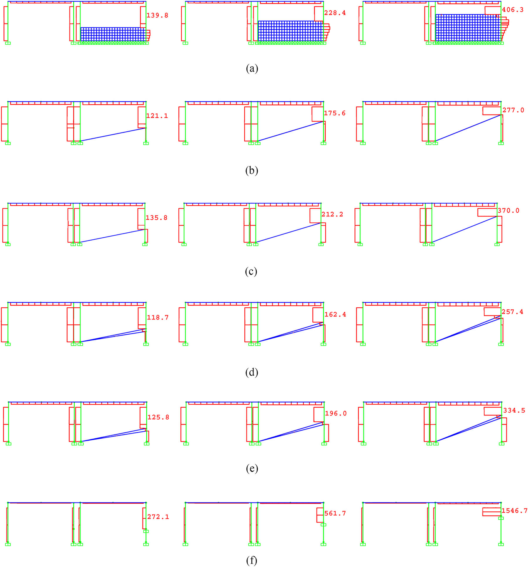
Figure 8
Six methods for modeling partially infilled frame and shear force diagram of a one-story, one-bay partially infilled frame with wall heights of 1/3, 1/2, and 2/3 of the frame height under the same displacement: (a) finite element, (b) New Zealand equivalent strut, (c) 0.2 d equivalent strut, (d) two struts with half of the width of New Zealand equivalent strut, (e) two struts with half of the width of 0.2 d equivalent strut, and (f) fixed support at the bottom of short column.
Source: Authors’ contribution.
Table 4
Six methods for modeling partially infilled frame and calculation of stiffness and shear force of a one-story, one-bay partially infilled frame with wall heights of 1/3, 1/2, and 2/3 of the frame height under the same force and the same displacement
| Stiffness | Shear in the right column under the same force | Shear in the right column under the same displacement | |||||||
|---|---|---|---|---|---|---|---|---|---|
| Ux (mm) | Kx (kN/m) | Infilled frame to bare frame (–) | Infilled frame (kN) | Infilled frame to bare frame (–) | Infilled frame (kN) | Bare frame (kN) | Infilled frame to bare frame (–) | ||
| Bare frame | 7.9 | 25,290 | — | 100 | — | — | — | — | |
| Partially infilled frame with wall height of 1/3 of the frame height | Finite element | 6.5 | 30,740 | 1.2 | 115.7 | 1.16 | 139.8 | 99.3 | 1.41 |
| New Zealand equivalent strut | 7.1 | 28,220 | 1.1 | 109.2 | 1.09 | 121.1 | 99.3 | 1.22 | |
| 0.2 d equivalent strut | 6.7 | 29,920 | 1.2 | 113.7 | 1.14 | 135.8 | 100.8 | 1.35 | |
| Two struts with half of the width of New Zealand equivalent strut | 7.3 | 27,520 | 1.1 | 107.2 | 1.07 | 118.7 | 99.5 | 1.19 | |
| Two struts with half of the width of 0.2 d equivalent strut | 6.9 | 28,900 | 1.1 | 111.1 | 1.11 | 125.8 | 96.9 | 1.30 | |
| Fixed support at the bottom of short column | 4.1 | 48,230 | 1.9 | 142.6 | 1.43 | 272.1 | 99.5 | 2.73 | |
| Partially infilled frame with wall height of 1/2 of the frame height | Finite element | 4.8 | 41,800 | 1.7 | 135.6 | 1.36 | 228.4 | 101.8 | 2.24 |
| New Zealand equivalent strut | 5.7 | 35,260 | 1.4 | 125.5 | 1.26 | 175.6 | 100.3 | 1.75 | |
| 0.2 d equivalent strut | 5.0 | 39,970 | 1.6 | 133.1 | 1.33 | 212.2 | 100.8 | 2.11 | |
| Two struts with half of the width of New Zealand equivalent strut | 5.9 | 33,650 | 1.3 | 122.3 | 1.22 | 162.4 | 97.5 | 1.67 | |
| Two struts with half of the width of 0.2 d equivalent strut | 5.3 | 37,740 | 1.5 | 129.6 | 1.30 | 196.0 | 99.0 | 1.98 | |
| Fixed support at the bottom of short column | 2.3 | 85,660 | 3.4 | 165.0 | 1.65 | 561.7 | 99.9 | 5.62 | |
| Partially infilled frame With wall height of 2/3 of the frame height | Finite element | 3.1 | 65,120 | 2.6 | 156.5 | 1.57 | 406.3 | 107.0 | 3.80 |
| New Zealand equivalent strut | 4.1 | 48,930 | 1.9 | 144.7 | 1.45 | 277.0 | 98.8 | 2.80 | |
| 0.2 d equivalent strut | 3.3 | 60,710 | 2.4 | 154.0 | 1.54 | 370.0 | 100.0 | 3.70 | |
| Two struts with half of the width of New Zealand equivalent strut | 4.4 | 45,880 | 1.8 | 141.3 | 1.41 | 257.4 | 98.1 | 2.62 | |
| Two struts with half of the width of 0.2 d equivalent strut | 3.6 | 56,030 | 2.2 | 150.5 | 1.51 | 334.5 | 98.0 | 3.41 | |
| Fixed support at the bottom of short column | 0.9 | 212,220 | 8.4 | 184.0 | 1.84 | 1546.7 | 99.7 | 15.51 | |
Source: Authors’ contribution.
The results of the analyses show that the 0.2 d equivalent strut method exhibits the closest behavior in term of stiffness and shear distribution under the same force and the same displacement to the finite element model. The extreme state of the models is related to the fixed support model, which is not applicable in multistory buildings. As the height of the infill wall increases, the stiffness of the system and the concentrated shear force in the short column increases under two conditions of the same force and the same displacement. For the fully infilled frame, the stiffness obtained using the New Zealand equivalent strut method is 99,680 kN/m, while the stiffness obtained using the 0.2 d equivalent strut method is 158,840 kN/m. Therefore, it can be concluded that in all methods, the stiffness of partially infilled frames is lower than fully infilled frames. The only exception is the partially infilled frame with an infill wall height of 2/3 of the frame height when it is modeled using a fixed support at the base of the short column. So, this method is not suitable for modeling partially infilled frame, as it may lead to physically unrealistic results.
4. The effect of wall stiffness on short column
In this section, the influence of the infill wall stiffness on the short column is investigated. For this purpose, the modulus of elasticity of infill wall is varied as 0.5, 2, and 10 times that of the original model. The infilled frame is modeled using the 0.2 d equivalent strut for three different infill wall heights. The shear force diagrams of the models under the same force and under the same displacement applied from right to left are demonstrated in Figures 9 and 10, respectively, while the corresponding numerical results are summarized in Table 5.
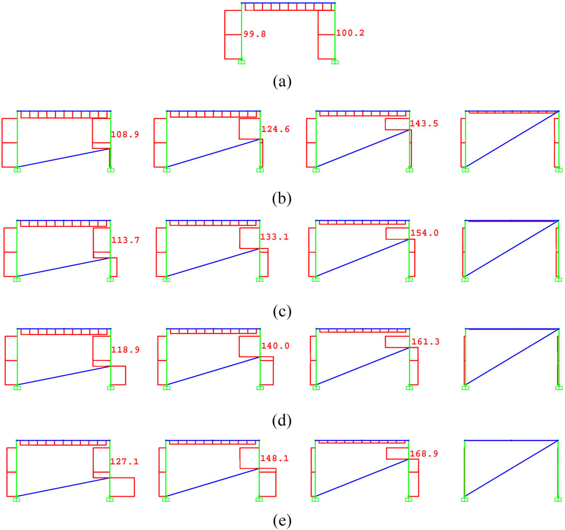
Figure 9
Shear force diagram of a one-story, one-bay partially infilled frame with wall heights of 1/3, 1/2, and 2/3 of the frame height, and fully infilled frame with different modulus of elasticity under the same force by using 0.2 d equivalent strut: (a) bare frame, (b) half of the original modulus of elasticity, (c) the original modulus of elasticity, (d) two times of the original modulus of elasticity, and (e) ten times of the original modulus of elasticity.
Source: Authors’ contribution.
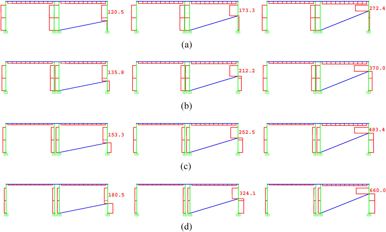
Figure 10
Shear force diagram of a one-story, one-bay partially infilled frame with wall heights of 1/3, 1/2, and 2/3 of the frame height with different modulus of elasticity under the same displacement by using 0.2 d equivalent strut: (a) half of the original modulus of elasticity, (b) the original modulus of elasticity, (c) two times of the original modulus of elasticity, and (d) ten times of the original modulus of elasticity.
Source: Authors’ contribution.
Table 5
Calculation of stiffness and shear force of a one-story one-bay partially infilled frame with heights of 1/3, ½, and 2/3, and fully infilled frame with different modulus of elasticity under the same force and the same displacement by using 0.2 d equivalent strut
| Stiffness | Shear in the right column under the same force | Shear in the right column under the same displacement | |||||||
|---|---|---|---|---|---|---|---|---|---|
| Ux (Mm) | Kx (kN/m) | Infilled frame to bare frame (–) | Infilled frame (kN) | Infilled frame to bare frame (–) | Infilled frame (kN) | Bare frame (kN) | Infilled frame to bare frame (–) | ||
| Bare frame | 7.9 | 25,290 | — | 100 | — | — | — | — | |
| Partially infilled frame with wall height of 1/3 of the frame height | 0.5E | 7.1 | 28,090 | 1.1 | 108.9 | 1.09 | 120.5 | 99.5 | 1.21 |
| E | 6.7 | 29,920 | 1.2 | 113.7 | 1.14 | 135.8 | 100.8 | 1.35 | |
| 2E | 6.2 | 32,170 | 1.3 | 118.9 | 1.19 | 153.3 | 101.3 | 1.51 | |
| 10E | 5.5 | 36,550 | 1.4 | 127.1 | 1.27 | 180.5 | 98.2 | 1.84 | |
| Partially infilled frame with wall height of 1/2 of the frame height | 0.5E | 5.8 | 34,750 | 1.4 | 124.6 | 1.25 | 173.3 | 101.1 | 1.71 |
| E | 5.0 | 39,970 | 1.6 | 133.1 | 1.33 | 212.2 | 100.8 | 2.11 | |
| 2E | 4.4 | 45,560 | 1.8 | 140.0 | 1.40 | 252.5 | 100.0 | 2.53 | |
| 10E | 3.7 | 54,430 | 2.2 | 148.1 | 1.48 | 324.1 | 101.5 | 3.19 | |
| Partially infilled frame with wall height of 2/3 of the frame height | 0.5E | 4.2 | 47,730 | 1.9 | 143.5 | 1.44 | 272.4 | 100.4 | 2.71 |
| E | 3.3 | 60,710 | 2.4 | 154.0 | 1.54 | 370.0 | 100.0 | 3.70 | |
| 2E | 2.7 | 75,120 | 3.0 | 161.3 | 1.61 | 483.4 | 100.7 | 4.80 | |
| 10E | 2.0 | 99,160 | 3.9 | 168.9 | 1.69 | 660.0 | 99.5 | 6.63 | |
| Fully infilled frame | 0.5E | 2.1 | 93,310 | 3.7 | — | — | — | — | — |
| E | 1.3 | 158,840 | 6.3 | — | — | — | — | — | |
| 2E | 0.7 | 283,050 | 11.2 | — | — | — | — | — | |
| 10E | 0.2 | 1,032,520 | 40.8 | — | — | — | — | — | |
Source: Authors’ contribution.
The results of the analyses indicate that the influence of increasing infill wall stiffness on the short-column response becomes more pronounced as the infill wall height increases. The effect of wall stiffness under the same force conditions is less than the same displacement conditions. It can be observed that increasing the stiffness of the infill wall does not lead to a substantial increase in the overall stiffness of the partially infilled frame when compared with a fully infilled frame. Therefore, wall stiffness is not an effective factor on the behavior of short column. Moreover, increasing the stiffness of short wall has a limited effect on increasing the shear force of the short column.
To confirm the results of linear analyses, three partially infilled frames with an infill wall height of 2/3 of the frame height, and three different modulus of elasticity of infill wall were analyzed nonlinearly. Flexural hinges were assigned at a distance of 0.05 L from both ends of the leeward column, while a shear hinge was assigned at a distance of 0.05 L above the top of the infill wall in the windward column. The corresponding pushover curves are presented in Figure 11, while the results summarized in Table 6 show that the ultimate strength of all models is approximately 250 kN, and short column failure occurs at displacements ranging from 3.8 to 5.2 mm. These results indicate that the modulus of elasticity of the infill wall has a negligible effect on the ultimate strength of the partially infilled frames, and only a minor influence on the displacement at which short-column failure occurs. This observation is consistent with the trends obtained from the linear analysis of models under the same displacement.
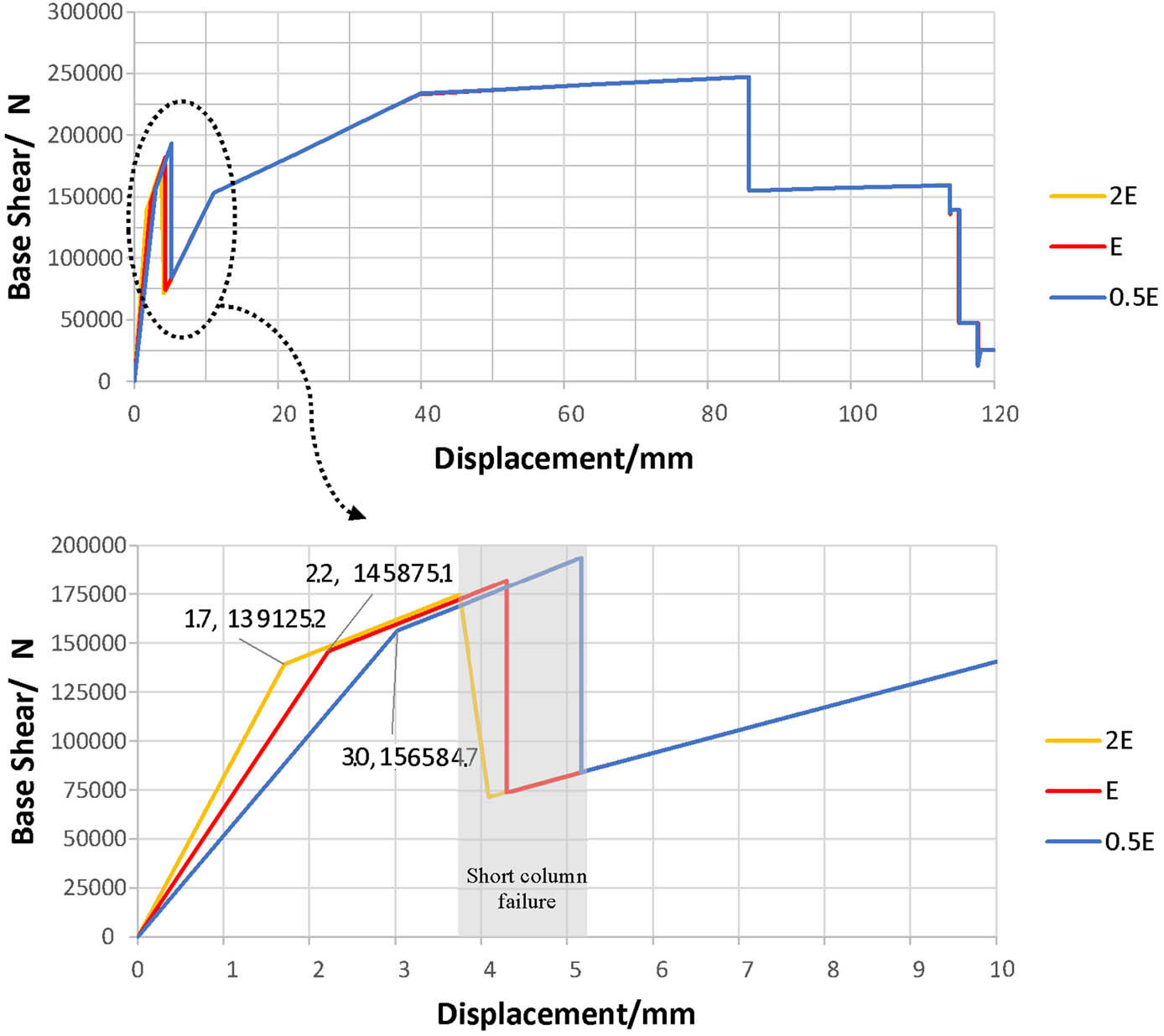
Figure 11
The pushover curves of three partially infilled frames with wall heights of 2/3 of the frame height with three different modulus of elasticity of infill wall.
Source: Authors’ contribution.
Table 6
Initial stiffness, ultimate strength, and lateral displacement in short column failure of three partially infilled frames with wall heights of 2/3 of the frame height with three different modulus of elasticity of infill wall
| Initial stiffness (kN/m) | Ultimate strength (kN) | Lateral displacement in short column failure (mm) | |
|---|---|---|---|
| 0.5E | 521,950 | 247.49 | 5.2 |
| E | 663,070 | 247.49 | 4.3 |
| 2E | 818,380 | 247.49 | 3.8 |
Source: Authors’ contribution.
5. The effect of adjacent frame conditions on the formation of short column
The analyses in previous sections show that the stiffness of a partially infilled frame is higher than a bare frame and lower than a fully infilled frame. Accordingly, in this section, the effect of adjacent frame conditions on the behavior of short column was studied. For this purpose, a one-story, two-bay frame was considered, in which one bay is partially infilled with a wall height equal to 2/3 of the frame height, while the adjacent bay is modeled under three different conditions: (i) a bare frame, (ii) a partially infilled frame, and (iii) a fully infilled frame. The systems were analyzed under a lateral force of 200 kN applied from right to left. The shear force diagrams under the same force and under the same displacement are demonstrated in Figures 12 and 13, respectively, while the corresponding numerical results are summarized in Table 7.
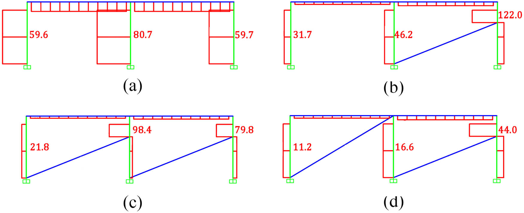
Figure 12
Shear force diagram of a one-story, two-bay frame under the same force by using 0.2 d equivalent strut: (a) two bare frames, (b) one partially infilled frame, one bare frame, (c) two partially infilled frames, (d) one partially infilled frame, one fully infilled frame.
Source: Authors’ contribution.
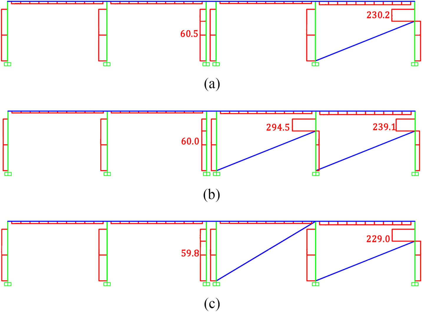
Figure 13
Shear force diagram of a one-story, two-bay frame under the same displacement by using 0.2 d equivalent strut: (a) one partially infilled frame, one bare frame, (b) two partially infilled frames, (c) one partially infilled frame, one fully infilled frame.
Source: Authors’ contribution.
Table 7
Calculation of stiffness and shear force of a one-story, two-bay partially infilled frame with different conditions of adjacent frame under the same force and the same displacement by using 0.2 d equivalent strut,
| Stiffness | Shear in the right column under the same force | Shear in the right column under the same displacement | ||||||
|---|---|---|---|---|---|---|---|---|
| Ux (mm) | Kx (kN/m) | Infilled frame to bare frame (–) | Infilled frame (kN) | Infilled frame to bare frame (–) | Infilled frame (kN) | Bare frame (kN) | Infilled frame to bare frame (–) | |
| Two bare frames | 4.9 | 40,510 | — | 59.7 | — | — | — | — |
| One partially infilled frame, one bare frame | 2.7 | 75,140 | 1.9 | 122.0 | 2.04 | 230.2 | 60.5 | 3.80 |
| Two partially infilled frames | 1.7 | 120,290 | 3.0 | 79.8 | 1.34 | 239.1 | 60.0 | 3.99 |
| One partially infilled frame, one fully infilled frame | 1.0 | 209,640 | 5.2 | 44.0 | 0.74 | 229.0 | 59.8 | 3.83 |
Source: Authors’ contribution.
The analyses results show that due to higher stiffness of partially infilled frame in comparison with bare frame and its lower stiffness in comparison with fully infilled frame, the shear force of short column under the same force depends on the conditions of adjacent frame. When the adjacent frame is fully infilled, the minimum shear force develops in the short column. In the studied frame, the shear force of short column is even lower than that of the bare frame. The shear force increases when both frames are partially infilled, while the maximum shear force occurs when the adjacent frame is bare. However, under the same displacement, the shear force of short column and its ratio to the shear force of bare frame in all different conditions are the same. Therefore, based on the explanations provided for the capacity-based design approach, it can be concluded that short column failure is expected to occur regardless of the conditions of adjacent frames.
To confirm the results of linear analyses, these models with different conditions of the adjacent frame were analyzed nonlinearly. The pushover curves are presented in Figure 14, and the results summarized in Table 8 indicate that both the initial stiffness and the ultimate strength of models depend on the conditions of the adjacent frame. The maximum initial stiffness is obtained when the adjacent frame is fully infilled. It decreases when both frames are partially infilled and reaches its minimum when the adjacent frame is bare. A different trend is observed for the ultimate strength. The highest ultimate strength is achieved when the adjacent frame is fully infilled, followed by the case with a bare adjacent frame, while the lowest ultimate strength is observed when both frames are partially infilled due to the failure of the short columns in both frames. In all models, short column failure occurs at displacements ranging from 3.8 to 4.6 mm. So, different conditions of the adjacent frame have no significant effect on the displacement where short column failure occurs. This observation is consistent with the results of the linear analyses of the models under the same displacement. The plastic hinges formed in the models within the displacement range of 3.8–4.6 mm are shown in Figure 15.
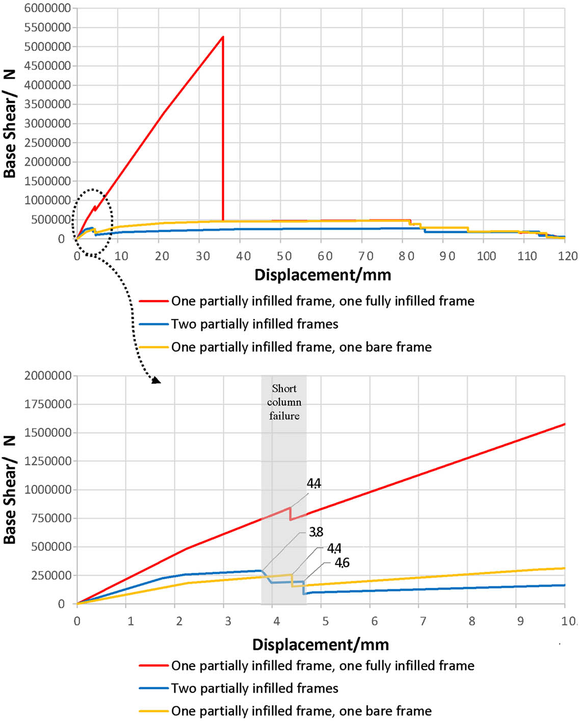
Figure 14
The pushover curves of three one-story, two-bay partially infilled frame with different conditions of adjacent frame.
Source: Authors’ contribution.
Table 8
Initial stiffness, ultimate strength, and lateral displacement in short column failure of three one-story, two-bay partially infilled frame with different conditions of adjacent frame
| Initial stiffness (kN/m) | Ultimate strength (kN) | Lateral displacement in short column failure (mm) | |
|---|---|---|---|
| One partially infilled frame, one bare frame | 81,080 | 472.70 | 04.4 |
| Two partially infilled frames | 130,170 | 272.15 | 3.8, 4.6 |
| 29.18 | |||
| One partially infilled frame, one fully infilled frame | 215,680 | 5257.64 | 4.4 |
Source: Authors’ contribution.
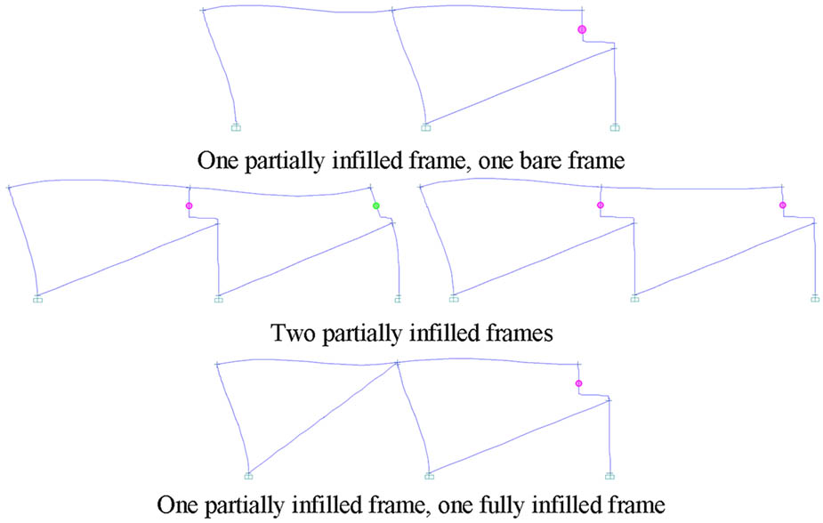
Figure 15
Formation of the plastic hinges in three one-story, two-bay partially infilled frame with different conditions of adjacent frame in the displacement range of 0.38–0.46 cm.
Source: Authors’ contribution.
6. Conclusion
In the present study, the results of the linear analyses were validated through nonlinear analyses. The findings demonstrate that linear analysis, despite its significantly lower computational cost and time, can provide valuable insight into structural behavior and distinguish between shear and flexural failure of concrete columns. This highlights the practical value of linear analysis as an efficient engineering tool.
The main results of the present study are summarized as follows:
The 0.2 d equivalent strut method provides the closest agreement with the finite element model in term of stiffness and shear distribution under the same force and the same displacement.
Increasing the height of the infill wall increases the stiffness of the system and the concentrated shear in the short column under both conditions of the same force and the same displacement.
Compared with a fully infilled frame, increasing the stiffness of the infill wall has little influence on the stiffness of partially infilled frame. In general, the stiffness of the infill wall is not a governing parameter in the behavior of short column.
Increasing the stiffness of short wall has only a limited effect on the shear force of the short column.
The stiffness of the infill wall has no significant effect on the ultimate strength of the partially infilled frame, and its effect on the displacement at which short column failure occurs is negligible. This observation from the nonlinear analyses is consistent with the results of the linear analyses performed under the same displacement.
Under the same force, the shear force of the short column depends on the conditions of adjacent frame. The minimum shear force occurs when the adjacent frame is fully infilled, increases when both frames are partially infilled, and reaches its maximum when the adjacent frame is bare.
Under the same displacement, the shear force of short column and its ratio to the shear force of bare frame remain unchanged regardless of the condition of the adjacent frame.
The results of the nonlinear analyses indicate that the initial stiffness of models depends on the conditions of the adjacent frame. The highest initial stiffness is obtained when the adjacent frame is fully infilled, followed by the case where both frames are partially infilled, while the lowest initial stiffness is observed when the adjacent frame is bare.
The results of the nonlinear analyses show that the ultimate strength of models depends on the conditions of the adjacent frame. The highest ultimate strength is achieved when the adjacent frame is fully infilled, followed by the case with a bare adjacent frame, whereas the lowest ultimate strength occurs when both frames are partially infilled due to short-column failure in both frames.
The results of the nonlinear analyses further demonstrate that different conditions of the adjacent frame have no significant effect on the displacement where short column failure occurs. This conclusion is consistent with the results of the linear analyses of the models under the same displacement. As a final result of the analyses, short wall in real buildings leads to the brittle short column failure regardless of the number of partially infilled, bare, or fully infilled frames within the structure.
Funding information
Authors state no funding involved.
Author contributions
Conceptualization: [Mohammad Reza Tabeshpour, Azadeh Noorifard], Methodology: [Mohammad Reza Tabeshpour, Azadeh Noorifard], Modeling and Formal analysis: [Azadeh Noorifard], Investigation the results: [Mohammad Reza Tabeshpour], Writing - original draft preparation, review and editing: [Azadeh Noorifard]; Literature review: [Azadeh Noorifard], Supervision: [Mohammad Reza Tabeshpour].
Conflict of interest statement
Authors state no conflict of interest.
Data availability statement
The data that support the findings of this study are available from the corresponding author, [Mohammad Reza Tabeshpour], upon reasonable request.