
Table 1
Simulation software used in flue system analysis: Advantages and limitations
| Software | Main capabilities | Advantages | Limitations |
|---|---|---|---|
| Kesa-aladin | Thermal, aerodynamic, and acoustic simulation of flue systems under real operating conditions |
|
|
| ANSYS Fluent | Computational fluid dynamics (CFD) for heat transfer and fluid flow |
|
|
| Energy Plus | Building energy modeling including HVAC and envelope components |
|
|
| COMSOL multiphysics | Multiphysics simulation, including heat transfer and structural performance |
|
|
| Solid works flow | Thermal and fluid dynamics simulation inside CAD-integrated environment |
|
|
| Simulation | |||
| Autodesk CFD | Simulation of airflow and temperature distribution |
|
|
| Open FOAM | Open-source CFD platform for customized simulations |
|
|
| Wufi Plus | Hygrothermal simulation of building components including airflows |
|
|
| TRNSYS | Transient system simulation for HVAC and energy systems |
|
|
Source: Refs. 36–45.
Table 2
Key output parameters in flue system analysis by simulation software
| Software | Thermal parameters | Fluid dynamics parameters | Structural/acoustic parameters | Additional features |
|---|---|---|---|---|
| Kesa-aladin | Flue gas temperature | Pressure drop | Acoustic transmission | Material compatibility |
| Heat loss | Flow velocity | Vibration behavior | Real-climate simulation | |
| Condensation risk | Turbulence levels | |||
| ANSYS Fluent | Heat transfer rate | Velocity vectors | Thermal stress (with coupling) | Soot deposition modeling |
| Temperature gradients | ||||
| Pressure distribution | ||||
| Combustion gas flow | ||||
| CFD turbulence | ||||
| EnergyPlus | Seasonal heating demand | Ventilation flow rates (simplified) | — | Energy efficiency metrics |
| Carbon emission estimates | ||||
| Fuel consumption | ||||
| COMSOL multiphysics | Heat flux | Flow resistance | Structural deformation | Coupled heat-structure-flow analysis |
| Thermal conductivity | ||||
| Material stress | ||||
| Airflow patterns | ||||
| SolidWorks flow simulation | Surface temperature | Internal airflow | — | Design iteration with CAD-based geometry |
| Pressure gradients | ||||
| Thermal loss | ||||
| Autodesk CFD | Cooling/heating loads | Laminar/turbulent flow paths | — | Cloud-based computing |
| Thermal comfort mapping | ||||
| Design visualization | ||||
| OpenFOAM | Temperature field | Dynamic pressure | – (can be extended with custom models) | Advanced scripting for transient and turbulent flow |
| Wall heat transfer rates | Flow separation | |||
| Wufi Plus | Dew point | Air leakage | — | Hygrothermal risk analysis |
| Water vapor diffusion | Moisture-related airflow | Climate-responsive simulations | ||
| TRNSYS | Time-based heat gain/loss | System airflow rates (HVAC) | — | Scenario simulation |
| Integration with renewable systems |
Table 3
Coverage of chimney components in simulation software
| Software | Cap | Flue pipe | Wall penetration | Shaft | Base/connection | Insulation layer |
|---|---|---|---|---|---|---|
| Kesa-aladin | ✓ | ✓ | ✓ | ✓ | ✓ | ✓ |
| ANSYS Fluent | ✓ | ✓ | ∼ | ✓ | ✓ | ∼ |
| EnergyPlus | × | ∼ | × | ∼ | ∼ | ∼ |
| COMSOL Multiphysics | ✓ | ✓ | ✓ | ✓ | ✓ | ✓ |
| SolidWorks Flow Sim. | ✓ | ✓ | ∼ | ∼ | ✓ | × |
| Autodesk CFD | ✓ | ✓ | ∼ | ∼ | ✓ | × |
| OpenFOAM | ✓ | ✓ | ✓ (custom) | ✓ | ✓ (custom) | ✓ (custom) |
| Wufi Plus | × | ∼ | ✓ | ∼ | × | ✓ |
| TRNSYS | × | ∼ | × | ∼ | ∼ | × |

|
| |||||
Source: Refs. 36–45.
Table 4
Computations and input and output parameters of Kesa-aladin simulation software [35]
| Software computations | Flue gas temperature profile |
| Flue gas velocity and density | |
| Pressure losses and draft behavior | |
| Sound levels generated by flue flow | |
| Heat losses through inner and outer chimney walls | |
| Wind speed effects under different external temperatures (±15°C) | |
| Input parameters | Boiler combustion data (fuel type, output power, exhaust temperature) |
| Chimney geometry and height | |
| Internal surface roughness coefficients for each material | |
| Outdoor air temperature and wind speed scenarios | |
| Insulation properties (Rockwool layer, stainless steel exterior, etc.) | |
| Output parameters | Mouth cross-sectional area (cm²) |
| Flow velocity (m/s) | |
| Flue gas density (kg/m³) | |
| Draft sound level (dBA) | |
| Wind interference velocity (m/s) at −15 and +15°C | |
| Stagnant pressure (Pa) | |
| Flue gas exit velocity (m/s) | |
| Maximum negative draft pressure (Pa) | |
| Flue gas temperature (°C) | |
| Inner wall and material surface temperature (°C) | |
| Insulation and outer wall temperature (°C) | |
| Direct airflow temperature and sidewall (R12) temperature (°C) |
Source: Author’s contribution.
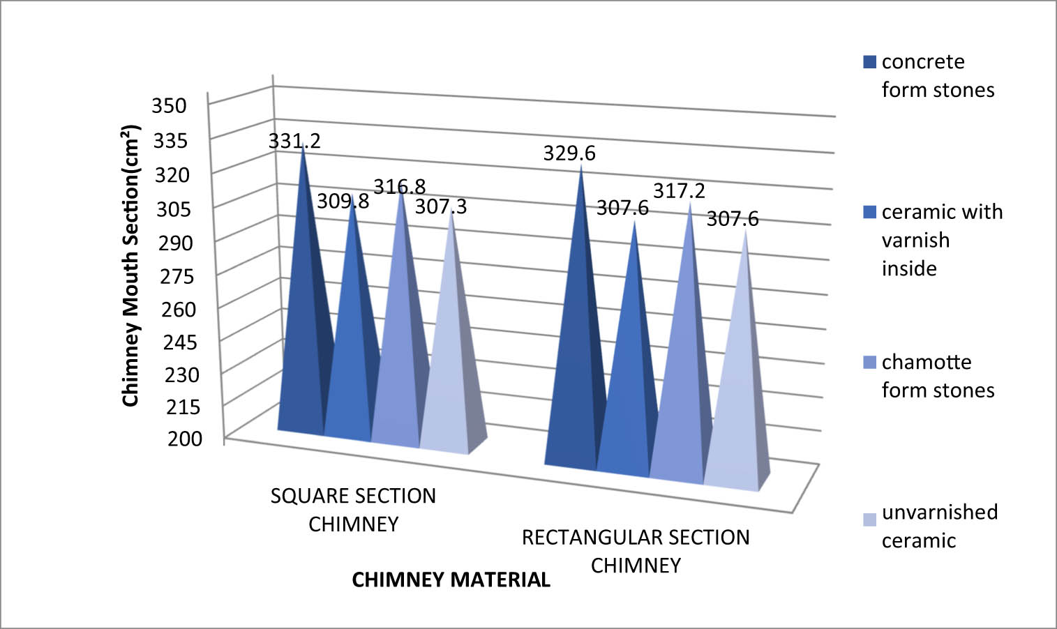
Figure 1
Comparison of rectangular and square form chimney mouth cross-section.
Source: Author’s contribution.
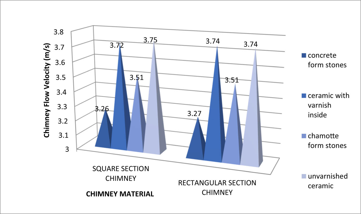
Figure 2
Comparison of stack flow velocity in rectangular and square form.
Source: Author’s contribution.
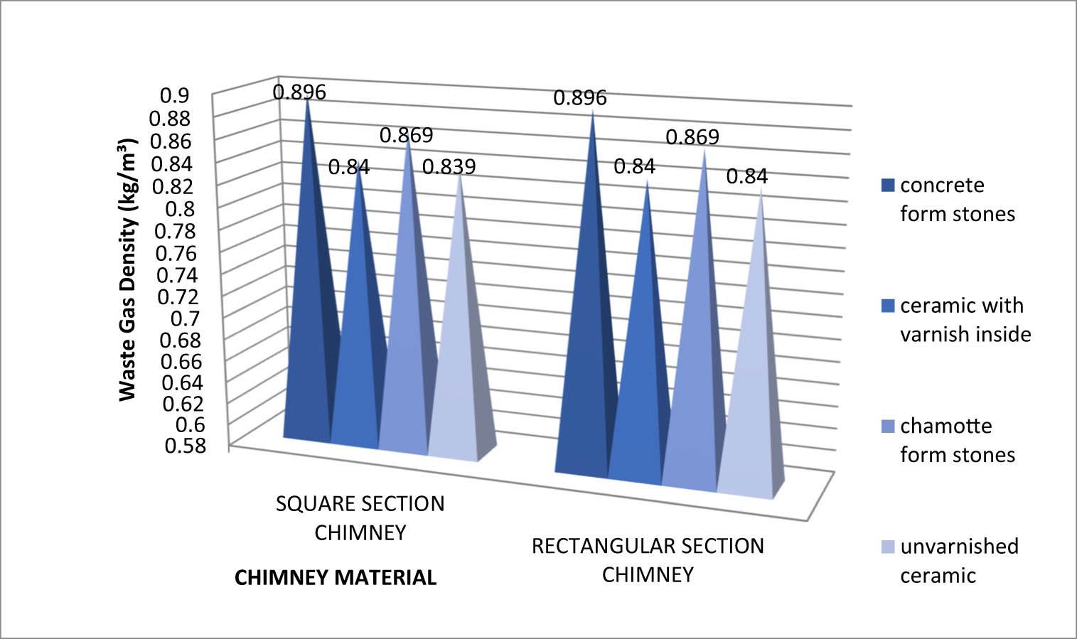
Figure 3
Comparison of flue gas density from rectangular and square stacks.
Source: Author’s contribution.
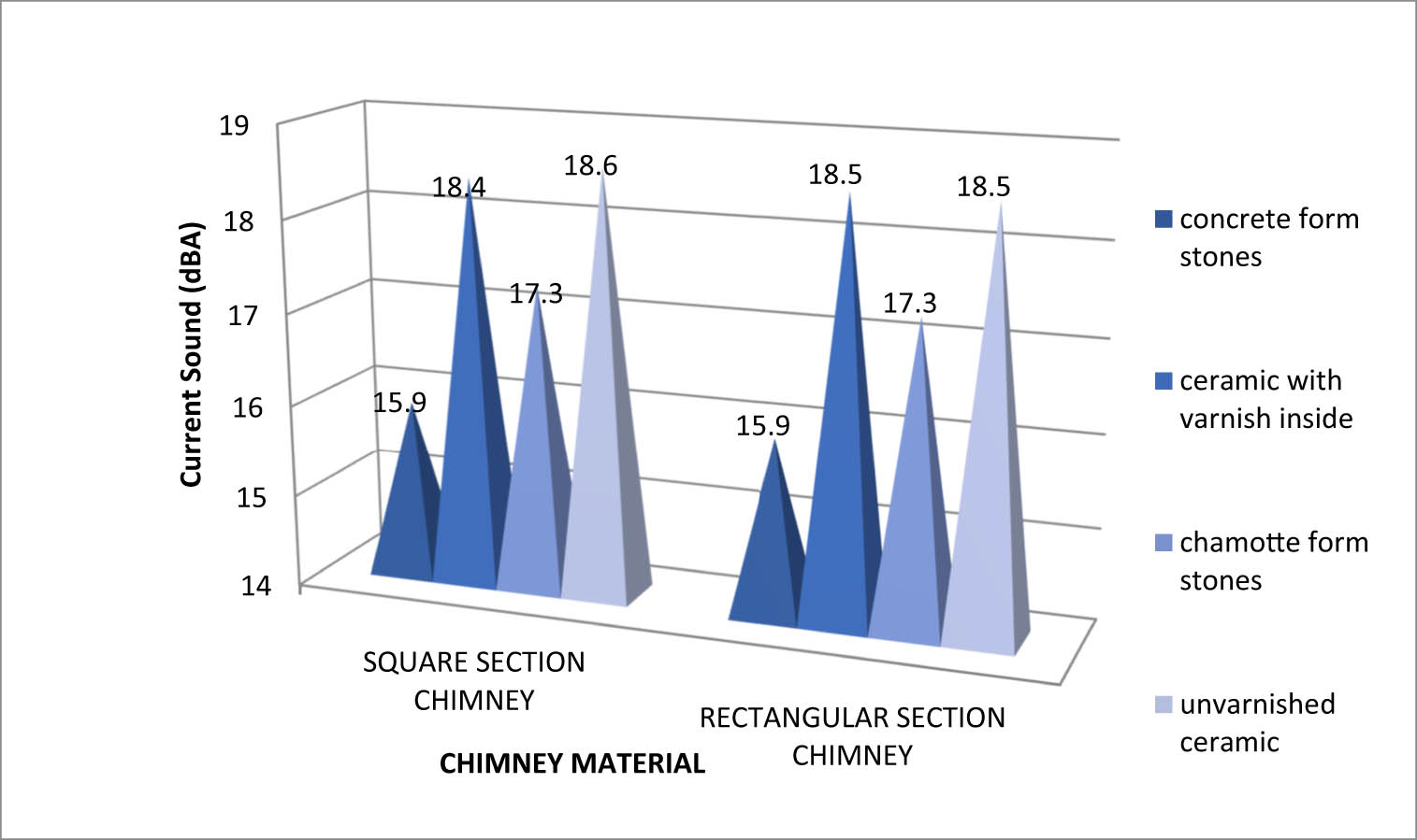
Figure 4
Comparison of chimney flow sound in rectangular and square forms.
Source: Author’s contribution.
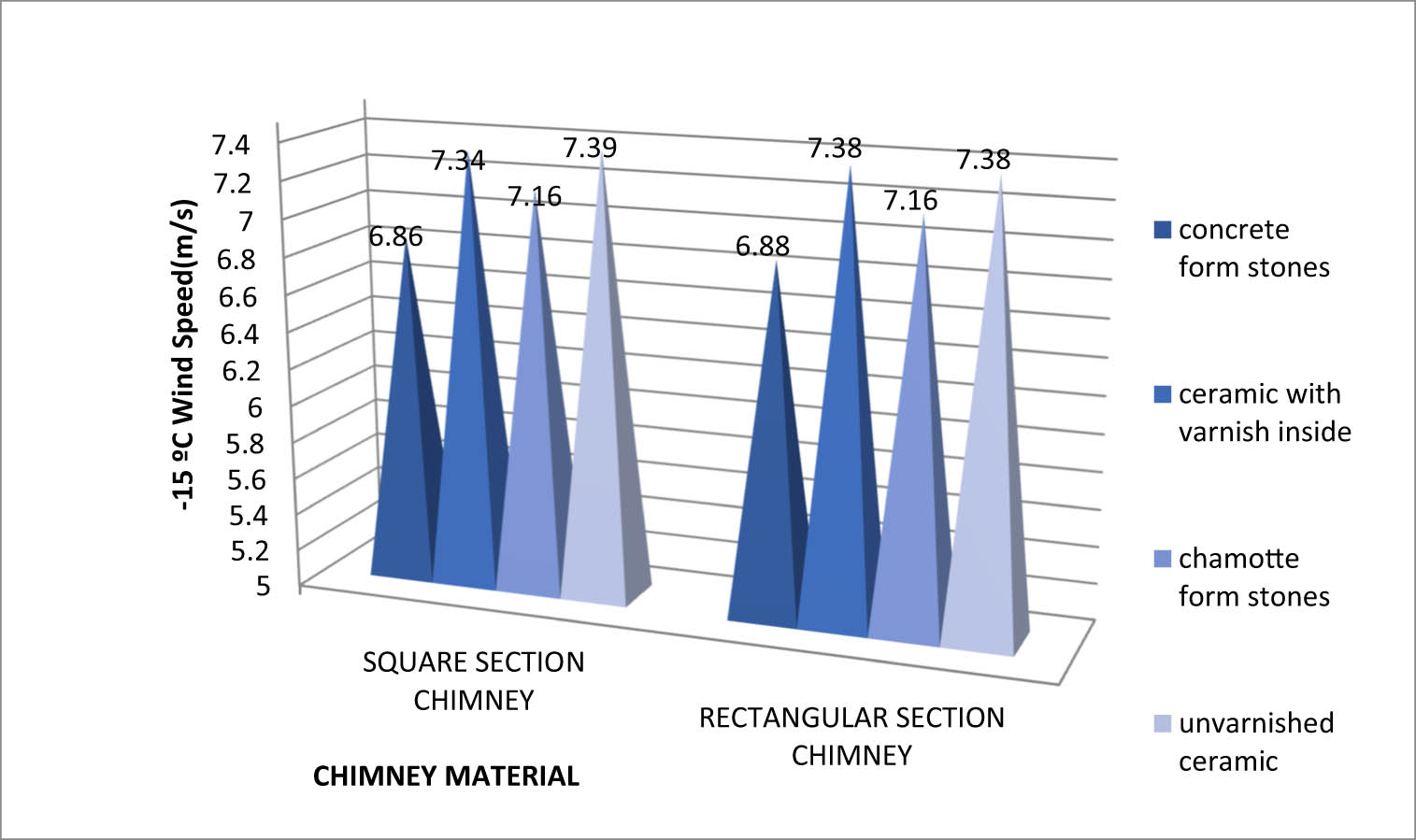
Figure 5
−15°C wind speed comparison for rectangular- and square-shaped chimneys.
Source: Author’s contribution.
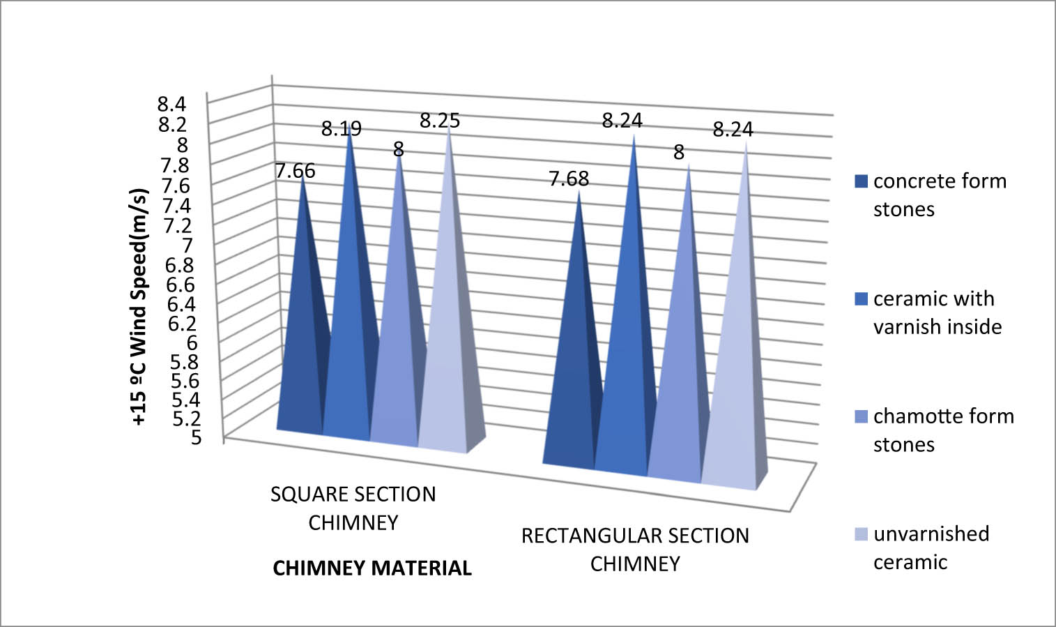
Figure 6
Comparison of wind speed (+15°C) of rectangular- and square-shaped chimney.
Source: Author’s contribution.
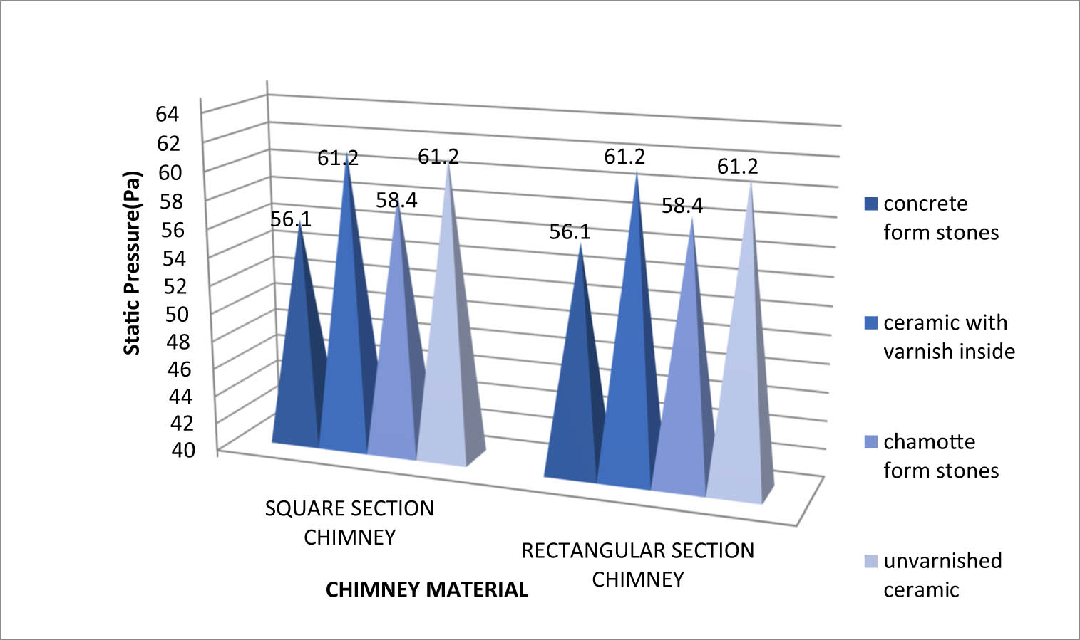
Figure 7
Comparison of stagnant pressure in rectangular- and square-shaped chimneys.
Source: Author’s contribution.
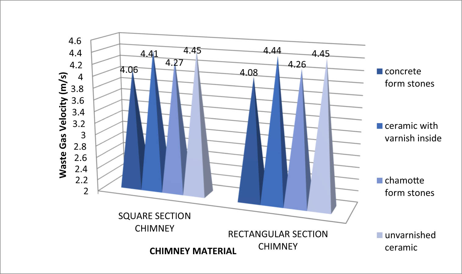
Figure 8
Comparison of flue gas velocity in rectangular- and square-shaped chimneys.
Source: Author’s contribution.
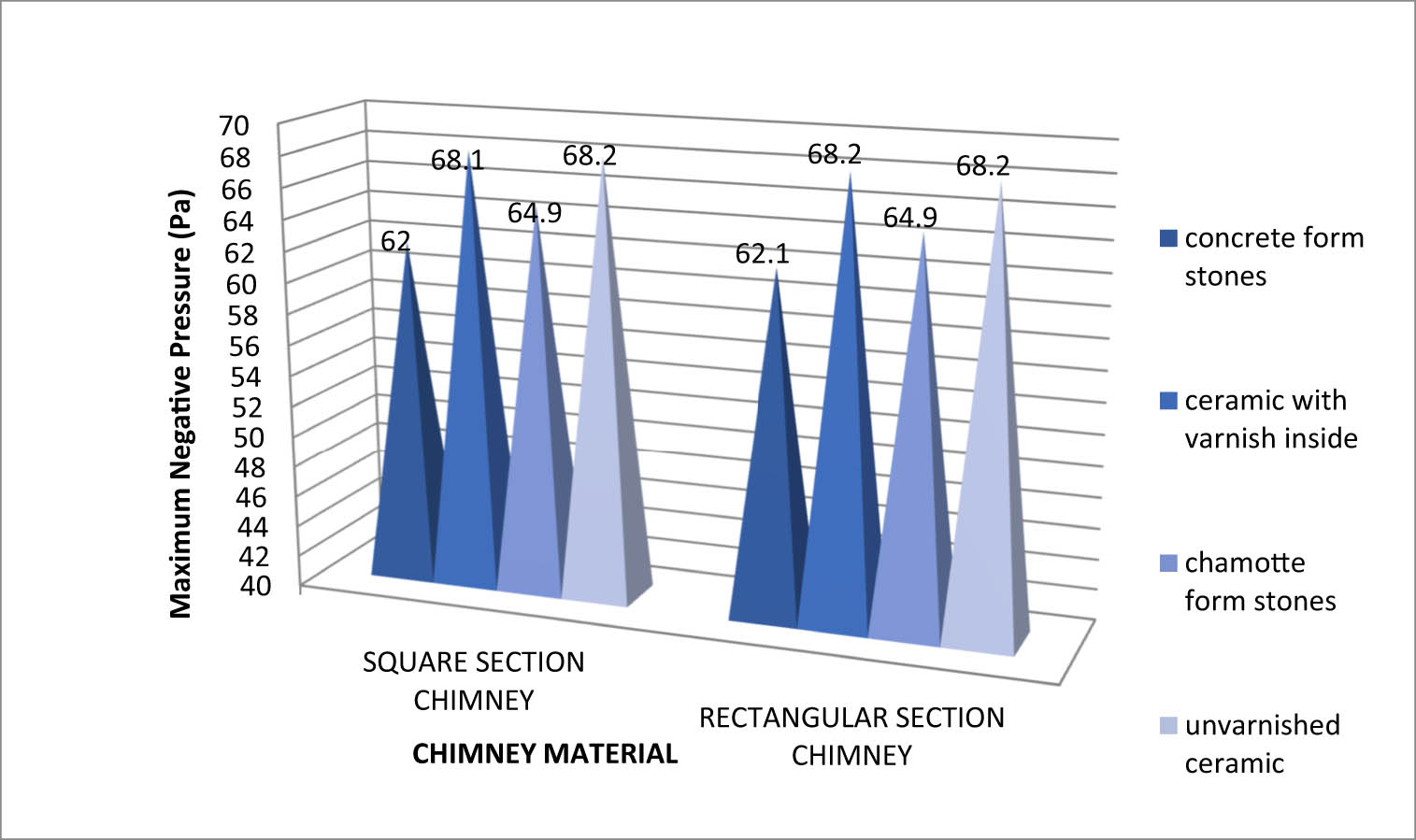
Figure 9
Comparison of maximum negative pressures of rectangular- and square-shaped chimneys.
Source: Author’s contribution.
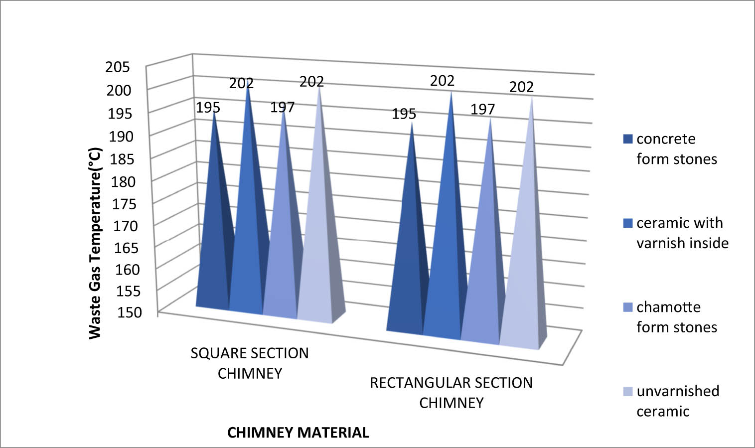
Figure 10
Temperature comparison of exhaust gases of rectangular- and square-shaped chimneys.
Source: Author’s contribution.
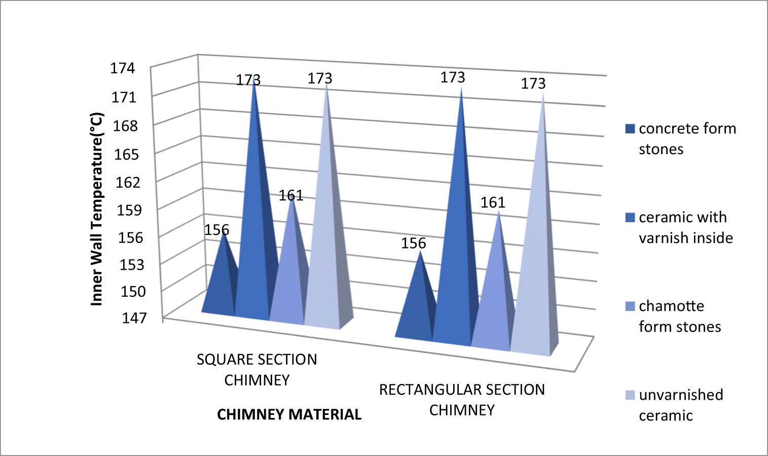
Figure 11
Temperature comparison of the inner wall of rectangular- and square-shaped exterior and interior chimneys.
Source: Author’s contribution.
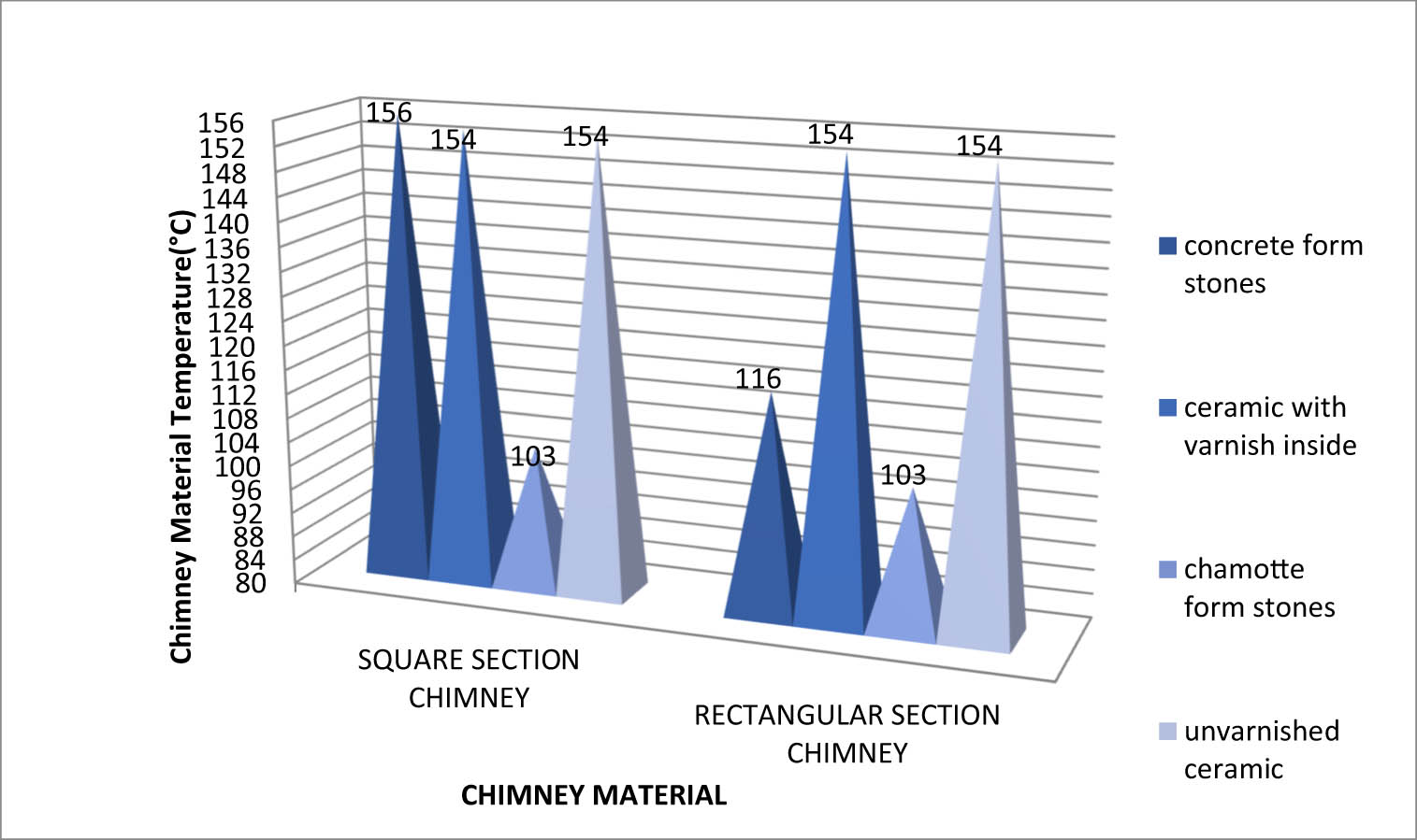
Figure 12
Comparison of temperature for rectangular and square flue materials.
Source: Author’s contribution.
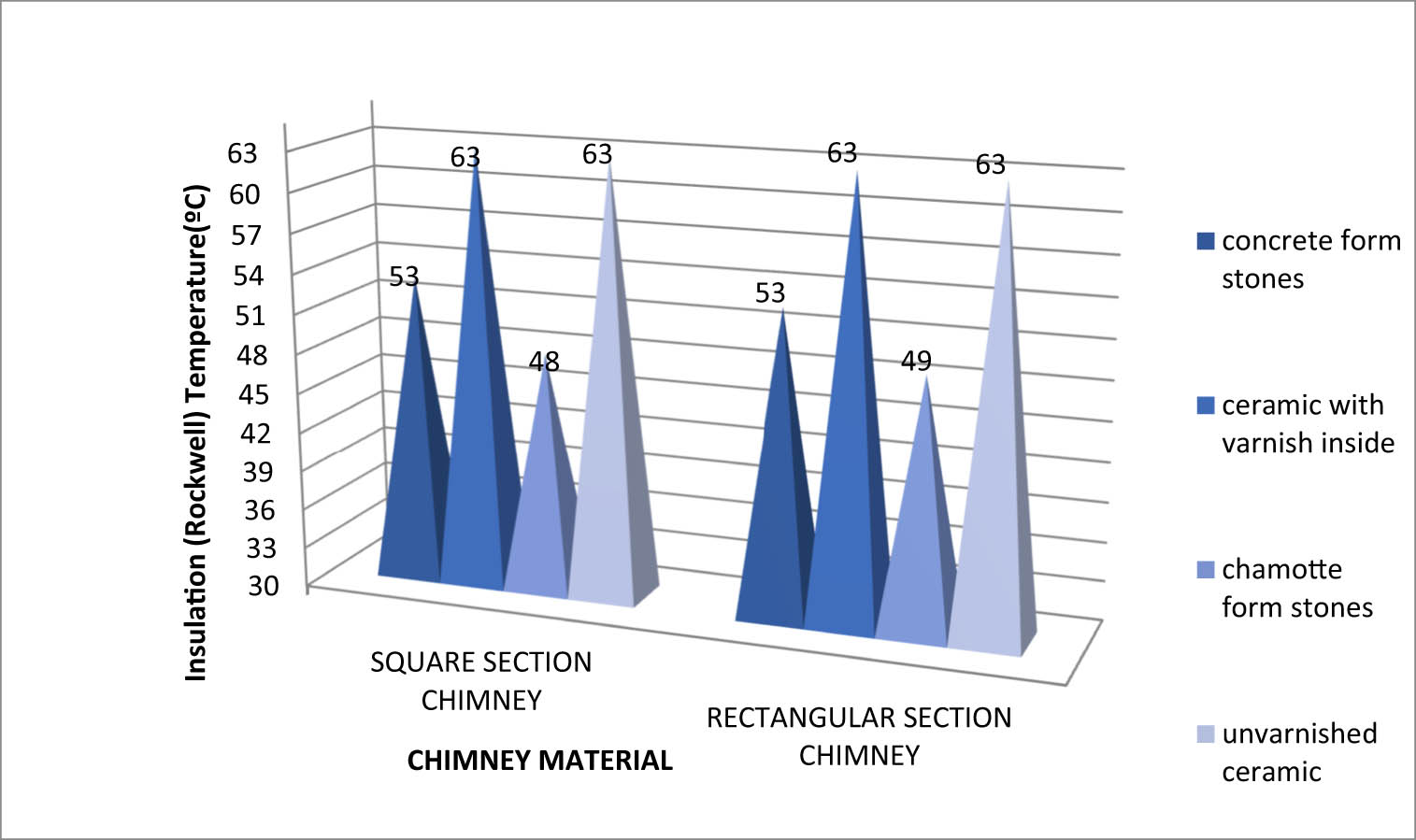
Figure 13
Temperature comparison of the material used in rectangular and square chimney insulation.
Source: Author’s contribution.
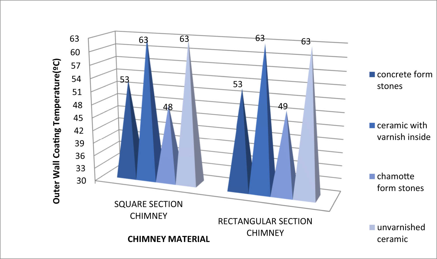
Figure 14
Temperature comparison of materials used in the outer wall coating of rectangular- and square-shaped chimneys.
Source: Author’s contribution.
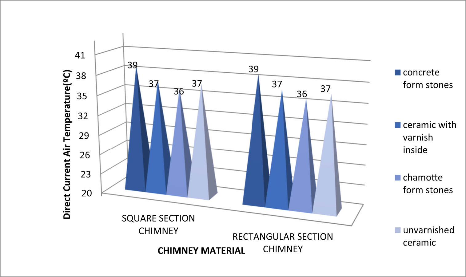
Figure 15
Comparison of air temperature in direct current of rectangular- and square-shaped chimneys.
Source: Author’s contribution.
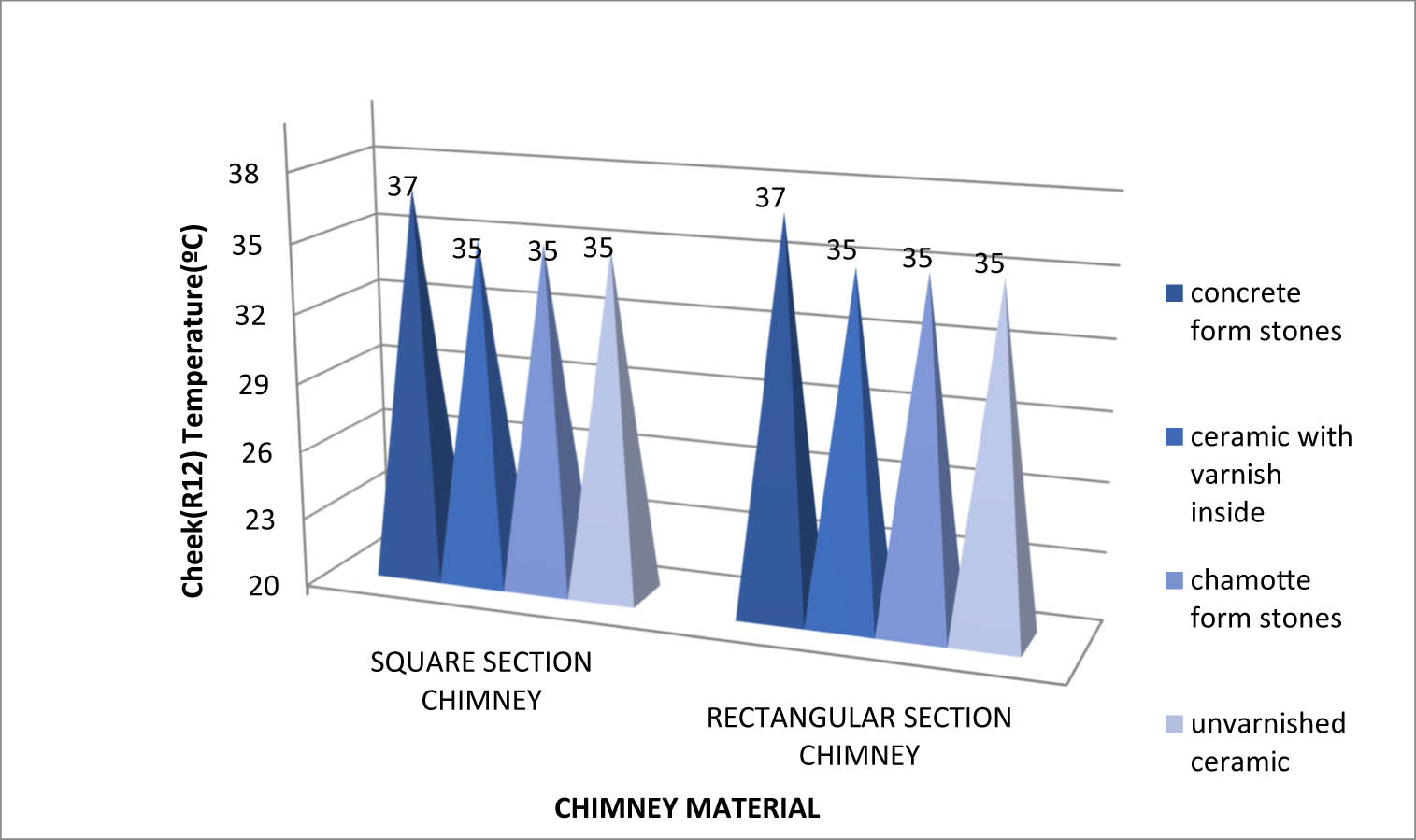
Figure 16
Rectangular- and square-shaped chimney sidewall (R12) temperature comparison.
Source: Author’s contribution.
Table 5
Maximum and minimum values of the outputs of the Kesa-aladin analysis
| Square section | Rectangular section | |||||||
|---|---|---|---|---|---|---|---|---|
| Concrete form stones | Varnished inside ceramic | Chamotte form stones | Unvarnished ceramic | Concrete form stones | Varnished inside ceramic | Chamotte form stones | Unvarnished ceramic | |
| Mouth section | 331.2 | 309.8 | 316.8 | 307.3 | 329.6 | 307.6 | 317.2 | 307.6 |
| Flow velocity | 3.26 | 3.72 | 3.51 | 3.75 | 3.27 | 3.74 | 3.51 | 3.74 |
| Fuel gas condensation | 0.896 | 0.84 | 0.869 | 0.839 | 0.896 | 0.84 | 0.869 | 0.84 |
| Flow noise | 15.9 | 18.4 | 17.3 | 18.6 | 15.9 | 18.5 | 17.3 | 18.5 |
| T – 15 | 6.86 | 7.34 | 7.16 | 7.39 | 6.88 | 7.38 | 7.16 | 7.38 |
| T + 15 | 7.66 | 8.19 | 8 | 8.25 | 7.68 | 8.24 | 8 | 8.24 |
| Static pressure | 56.1 | 61.2 | 58.4 | 61.2 | 56.1 | 61.2 | 58.4 | 61.2 |
| Fuel gas velocity | 4.06 | 4.41 | 4.27 | 4.45 | 4.08 | 4.44 | 4.26 | 4.45 |
| Maximum negative pressure | 62 | 68.1 | 64.9 | 68.2 | 62.1 | 68.2 | 64.9 | 68.2 |
| Fuel gas | 195 | 202 | 197 | 202 | 195 | 202 | 197 | 202 |
| Inner wall | 156 | 173 | 161 | 173 | 156 | 173 | 161 | 173 |
| Stainless steel | 156 | 154 | 163 | 154 | 116 | 154 | 103 | 154 |
| Rockwool | 53 | 63 | 48 | 63 | 53 | 63 | 49 | 63 |
| Outer wall, steel | 53 | 63 | 48 | 63 | 53 | 63 | 49 | 63 |
| Direction air | 39 | 37 | 36 | 37 | 39 | 37 | 36 | 37 |
| Sidewall (R12) | 37 | 35 | 35 | 35 | 37 | 35 | 35 | 35 |
Source: Author’s contribution.
Table 6
Feature importance ranking for chimney performance based on random forest regression analysis
| Rank | Feature | Importance |
|---|---|---|
| 1 | Maximum negative pressure | 0.42 |
| 2 | Flow velocity | 0.31 |
| 3 | Inner wall temperature | 0.10 |
| 4 | Insulation temperature | 0.09 |
| 5 | Flow sound | 0.08 |
Source: Author’s contribution.
Table 7
Comparison of TOPSIS and VIKOR methodologies
| Criteria | TOPSIS methodology | VIKOR methodology |
|---|---|---|
| Advantages | Considers both the ideal and anti-ideal solutions. | Balances group utility (majority rule) and individual regret (minority opposition). |
| Simple, intuitive, and easy to implement. | Effective in compromise decision-making. | |
| Provides clear ranking of alternatives. | Suitable for problems with conflicting criteria. | |
| Computationally efficient for large datasets. | Flexible for decision contexts requiring trade-offs. | |
| Disadvantages | Results are highly sensitive to the normalization method used. | Requires determining a compromise parameter (v), which may affect results. |
| Does not explicitly address conflict between criteria. | More complex to explain to non-experts. | |
| Distances may not fully capture decision-maker preferences. | Can produce rank reversals depending on dataset changes. | |
| Limitations | Assumes criteria weights are reliable and predetermined. | Sensitive to the selection of normalization and aggregation strategies. |
| Ignores uncertainty and fuzziness in input data unless extended versions (e.g., Fuzzy TOPSIS) are applied. | Performance depends on the accuracy of criteria weights and compromise parameter. | |
| Usage fields | Engineering design optimization. | Public policy and social decision-making. |
| Supplier and vendor selection. | Conflict resolution in resource allocation. | |
| Energy system evaluation. | Sustainable development planning. | |
| Environmental management and sustainability studies. | Healthcare and risk management decisions. |
Source: Author’s contribution.
Table 8
Comparative ranking of chimney alternatives using TOPSIS and VIKOR methods
| Geometry | Material | TOPSIS score | TOPSIS rank | VIKOR Q | VIKOR rank |
|---|---|---|---|---|---|
| Square | Chamotte form stones | 0.698 | 1 | 0.035 | 1 |
| Rectangular | Chamotte form stones | 0.685 | 2 | 0.044 | 2 |
| Rectangular | Concrete form stones | 0.498 | 3 | 0.984 | 7 |
| Square | Concrete form stones | 0.493 | 4 | 1.000 | 8 |
| Square | Unvarnished ceramic | 0.426 | 5 | 0.500 | 3 |
| Rectangular | Unvarnished ceramic | 0.426 | 6 | 0.504 | 4 |
| Rectangular | Varnished internal ceramic | 0.425 | 7 | 0.506 | 5 |
| Square | Varnished internal ceramic | 0.416 | 8 | 0.532 | 6 |
Source: Author’s contribution.