
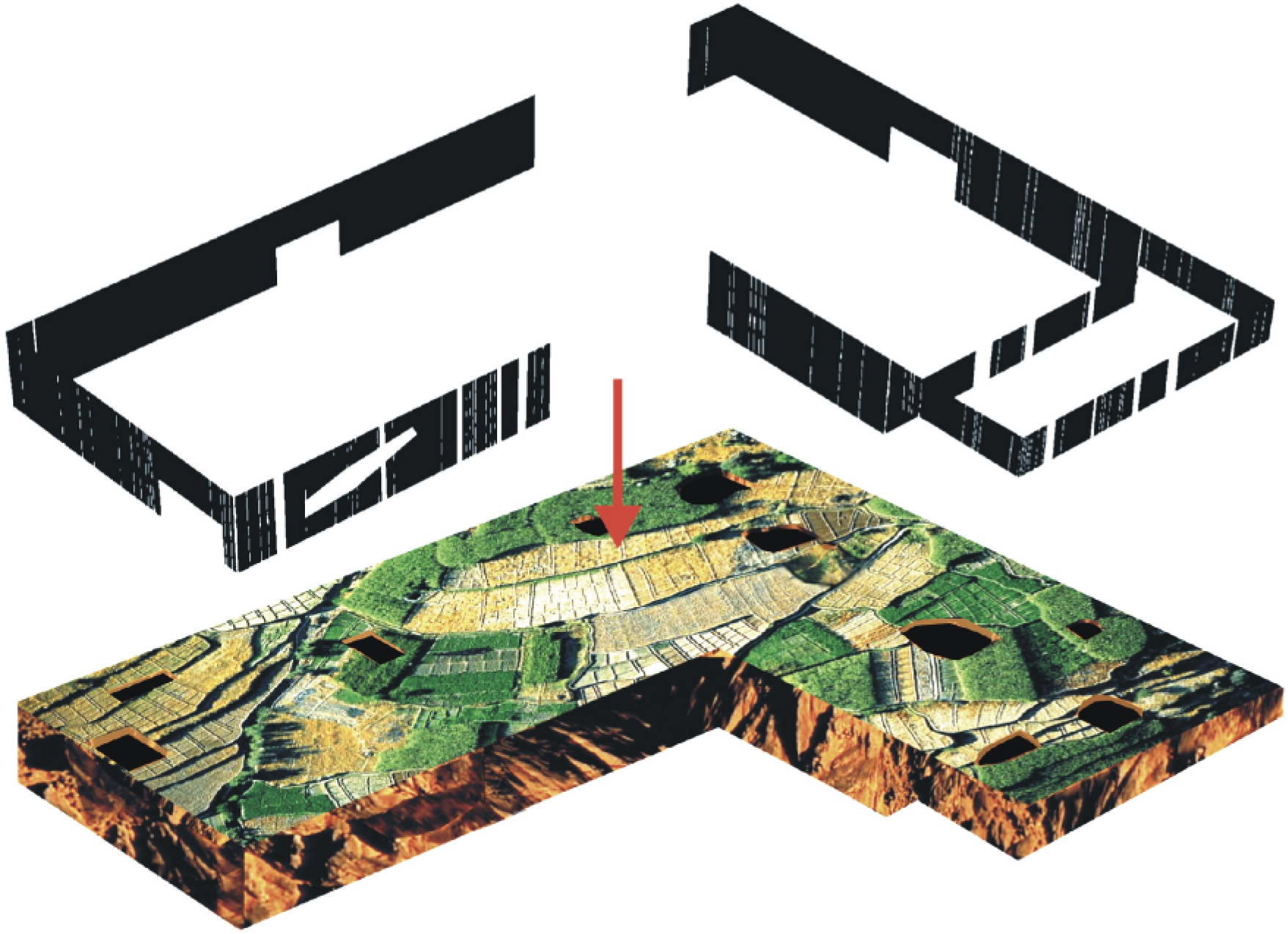
Figure 1.
Copernicus Science Centre – competition schematic diagram. Drawing from Author’s archive
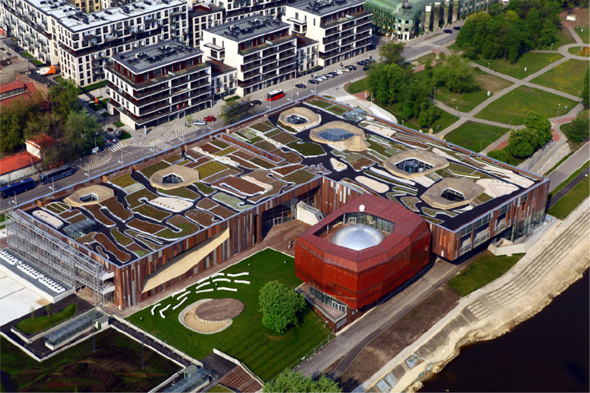
Figure 2.
Copernicus Science Centre – bird’s eye view. Photo from Author’s archive
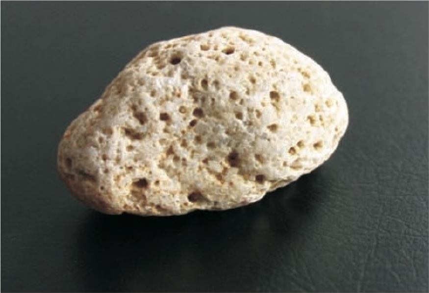
Figure 3.
Stone with small wholes. Author’s photo
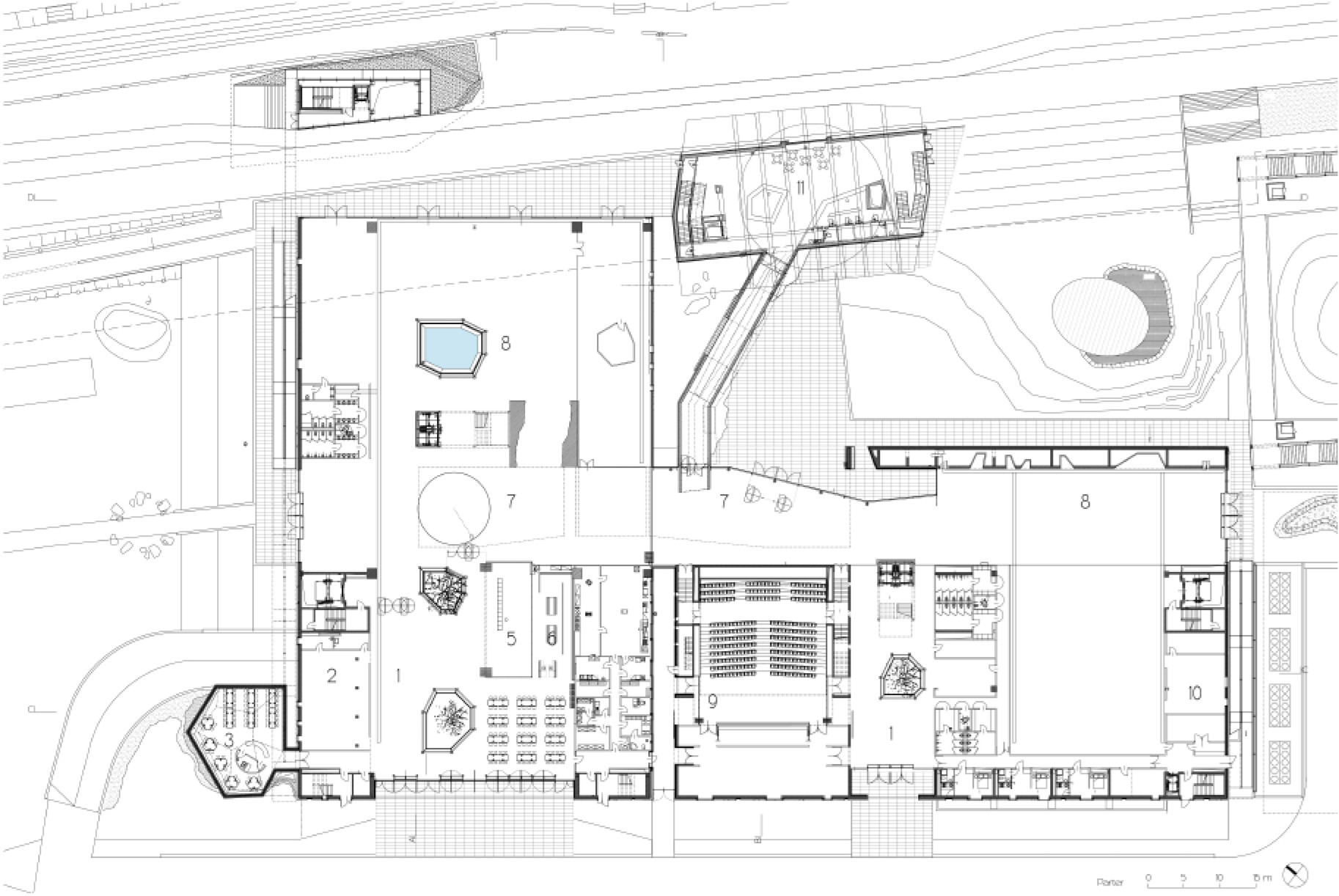
Figure 4.
Ground floor plan. 1 – foyer; 2 – dressing room; 3 – common room; 4 – ticket office; 5 – shop; 6 – cafeteria; 7 – agora; 8 – exhibition; 9 – auditorium; 10 – laboratory; 11 – planetarium foyer. Author’s drawing
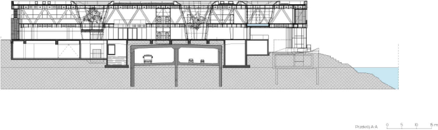
Figure 5.
Cross section A-A; Author’s drawing
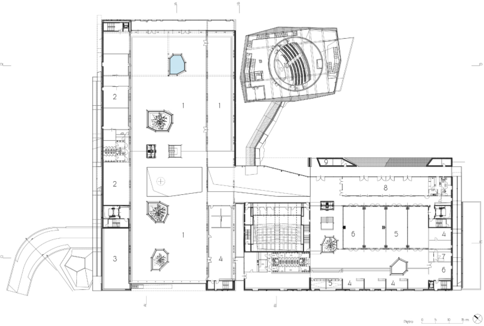
Figure 6.
First floor plan. 1 – exhibition; 2 – school laboratories; 3 – outdoor terrace; 4 – office; 5 – conference room; 6 – hall; 7 – dressing room; 8 – cafeteria; 9 – technical room; 10 – planetarium. Author’s drawing
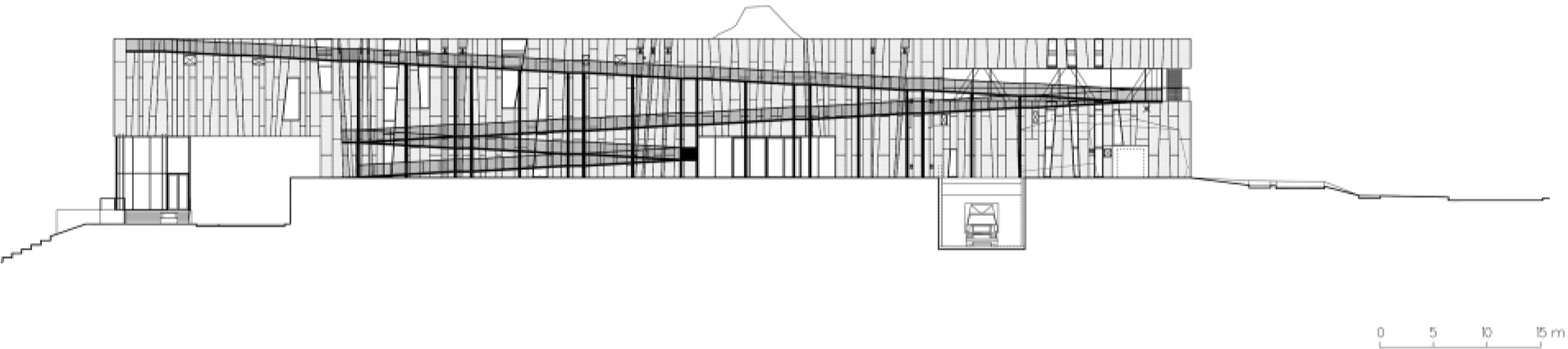
Figure 7.
North elevation. Visible ramp allows access to the roof of the Copernicus Science Centre without having to enter the building. Author’s drawing
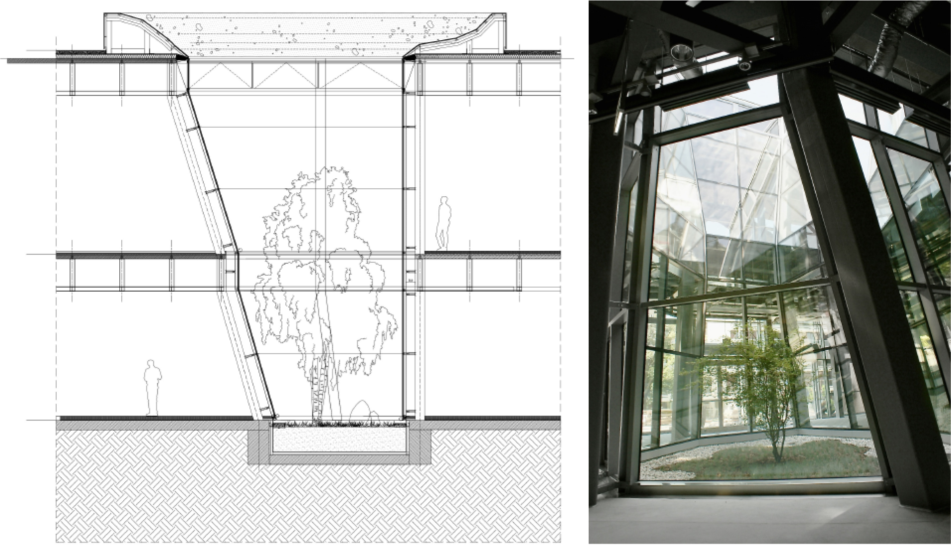
Figure 8.
Patio/crater – cross section and view; Author’s drawing and photo
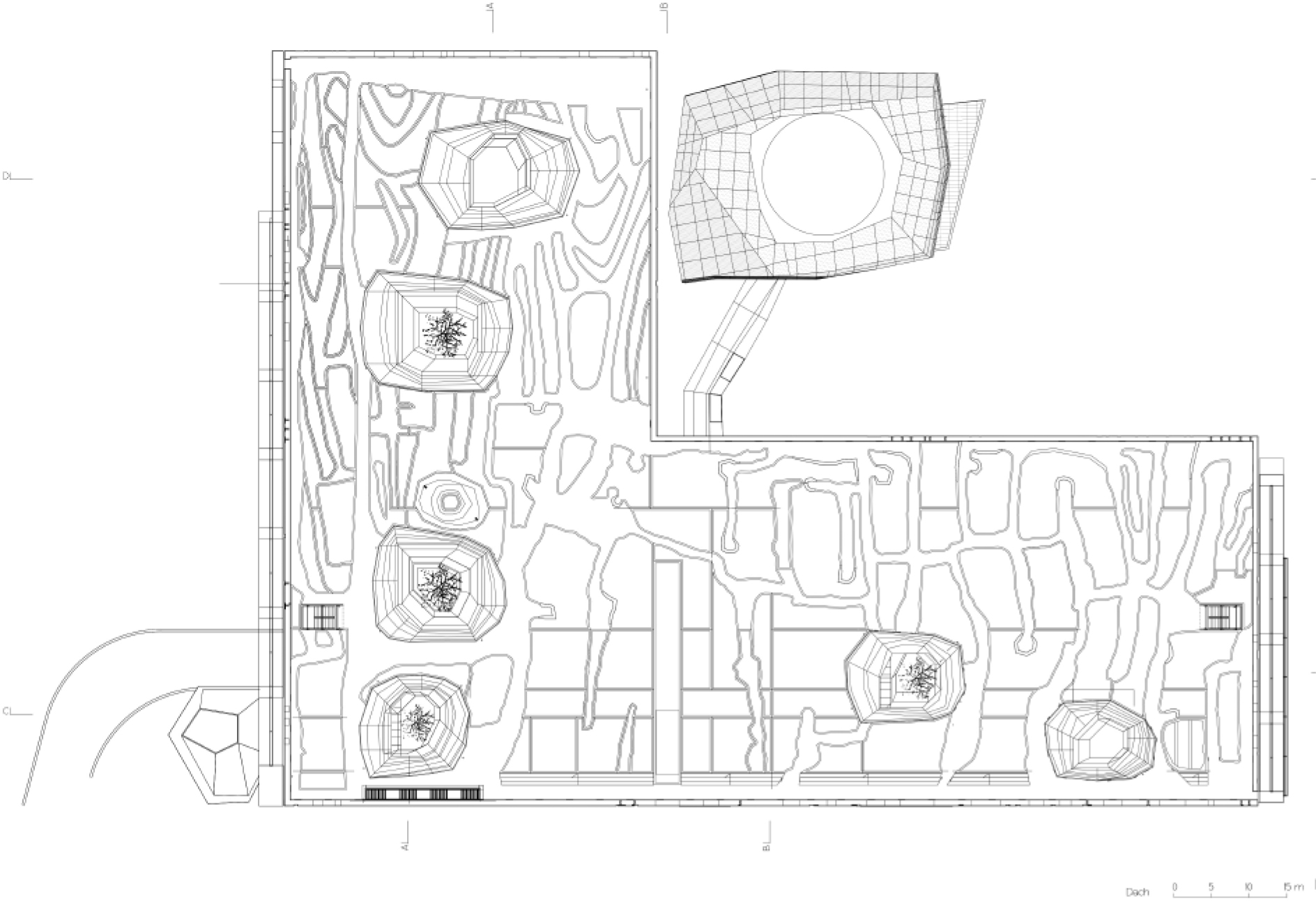
Figure 9.
Roof plan. From the description of the competition work: the greatest phenomenon of river and rain activity – erosion – becomes a stage for the creation of a new roofscape code. Author’s drawing
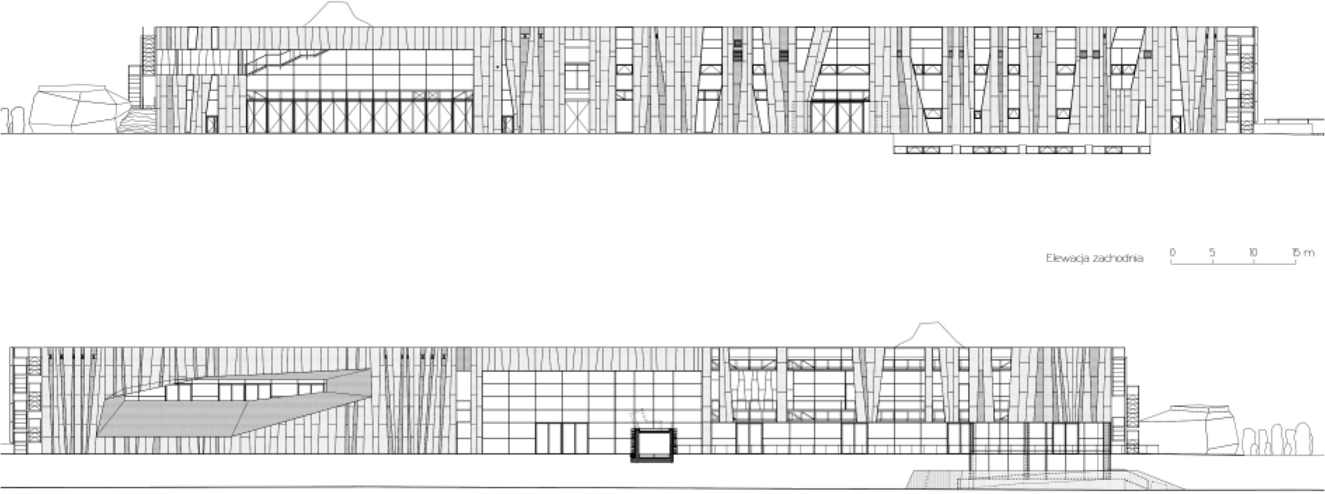
Figure 10.
West and East elevations (without planetarium). Author’s drawing
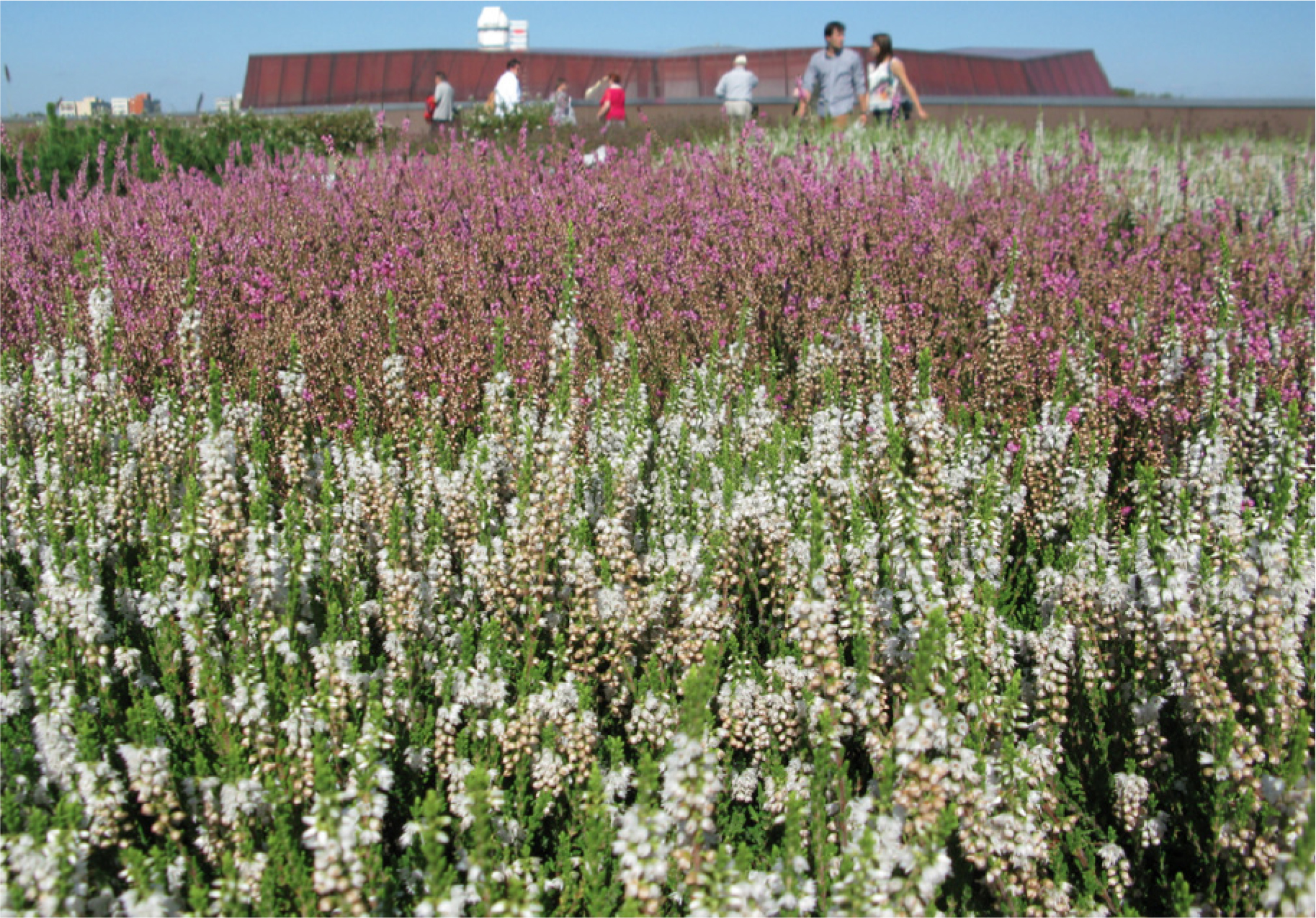
Figure 11.
Roof garden. Author’s photo. Today the roof garden is an oasis of green, but the project is working to increase habitat throughout the neighborhood and city through ongoing scientific partnerships and community engagement