
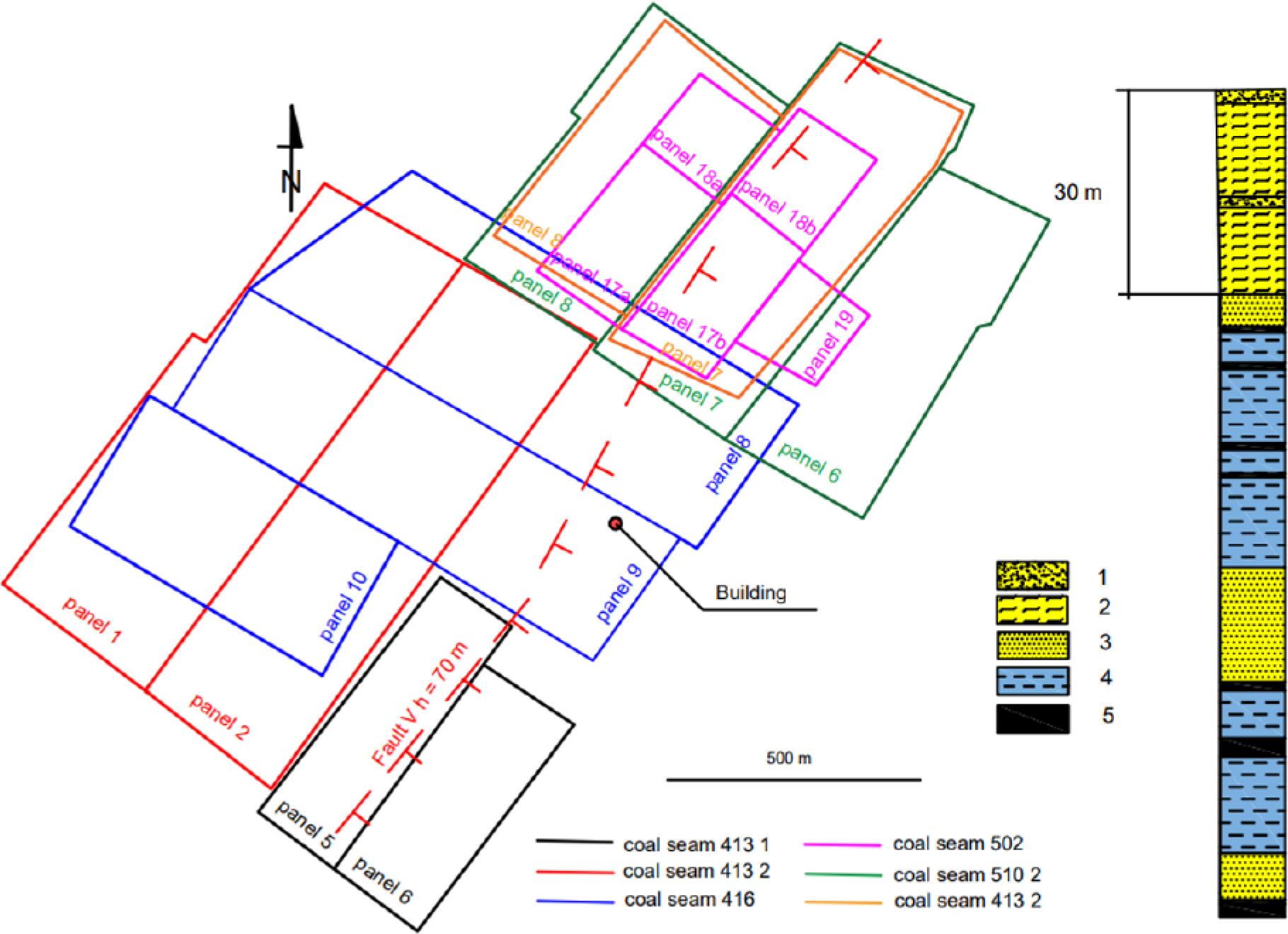
Figure 1.
Diagram of the location of the building in relation to selected walls and the lithological profile of the rock mass; 1 – sands, 2 – clays, 3 – sandstone, 4 – shale, 5 – coal
Table 1.
Basic information on geological and mining conditions of the exploitation
| Coal seam | Wall/parcel | Beginning of expl. | End of expl. | Coal seam thick. [m] | Dipp. ang. [deg] | Dep. [m] | Dist. [km] | Dir. | Ang. [deg] | a | System |
|---|---|---|---|---|---|---|---|---|---|---|---|
| 4131 | sc_5 | 01-10-2003 | 30-06-2004 | 1.8 | 5 | 640 | 0.30 | SW | 65 | 0.60 | zd |
| 4131 | sc_6 | 01-07-2003 | 31-03-2004 | 1.8 | 5 | 640 | 0.38 | SW | 59 | 0.60 | zd |
| 4132 | sc_1 | 01-07-1999 | 10-09-2000 | 2.4 | 5 | 610 | 0.55 | W | 48 | 0.60 | zd |
| 4132 | sc_2 | 15-12-2000 | 30-09-2002 | 2.4 | 5 | 610 | 0.25 | W | 68 | 0.60 | zd |
| 416 | sc_10 | 01-10-2003 | 01-06-2004 | 1.8 | 5 | 685 | 0.44 | W | 57 | 0.80 | z |
| 416 | sc_8 | 20-03-2000 | 21-01-2002 | 1.8 | 5 | 625 | 0.03 | NW | 87 | 0.80 | z |
| 416 | sc_9 | 01-07-2001 | 18-04-2003 | 2 | 5 | 655 | 0.00 | Bezp | 90 | 0.80 | z |
| 502 | 18a | 01-09-2007 | 31-03-2008 | 3 | 5 | 720 | 0.33 | NE | 65 | 0.25 | ph |
| 502 | 18b | 01-04-2008 | 01-09-2008 | 2.5 | 5 | 700 | 0.65 | NE | 47 | 0.80 | z |
| 502 | sc_17a | 01-04-2006 | 31-12-2006 | 3 | 5 | 720 | 0.38 | N | 62 | 0.25 | ph |
| 502 | sc_17b | 01-01-2007 | 01-04-2007 | 2.5 | 5 | 700 | 0.66 | N | 47 | 0.80 | z |
| 502 | sc_19 | 01-12-2008 | 03-08-2009 | 3 | 5 | 690 | 0.43 | NE | 58 | 0.25 | ph |
| 5102 | sc_6 | 01-10-2000 | 01-08-2001 | 2 | 5 | 790 | 0.27 | NE | 71 | 0.60 | zd |
| 5102 | sc_7 | 01-12-2001 | 01-10-2002 | 2 | 5 | 795 | 0.26 | NE | 72 | 0.60 | zd |
| 5102 | sc_8 | 01-05-2002 | 31-07-2003 | 2 | 5 | 800 | 0.36 | N | 66 | 0.60 | zd |
| 5103 | sc_7 | 01-06-2004 | 25-03-2005 | 2 | 5 | 800 | 0.33 | NE | 68 | 0.60 | zd |
| 5103 | sc_8 | 01-01-2005 | 01-08-2005 | 2 | 5 | 800 | 0.41 | N | 63 | 0.60 | zd |
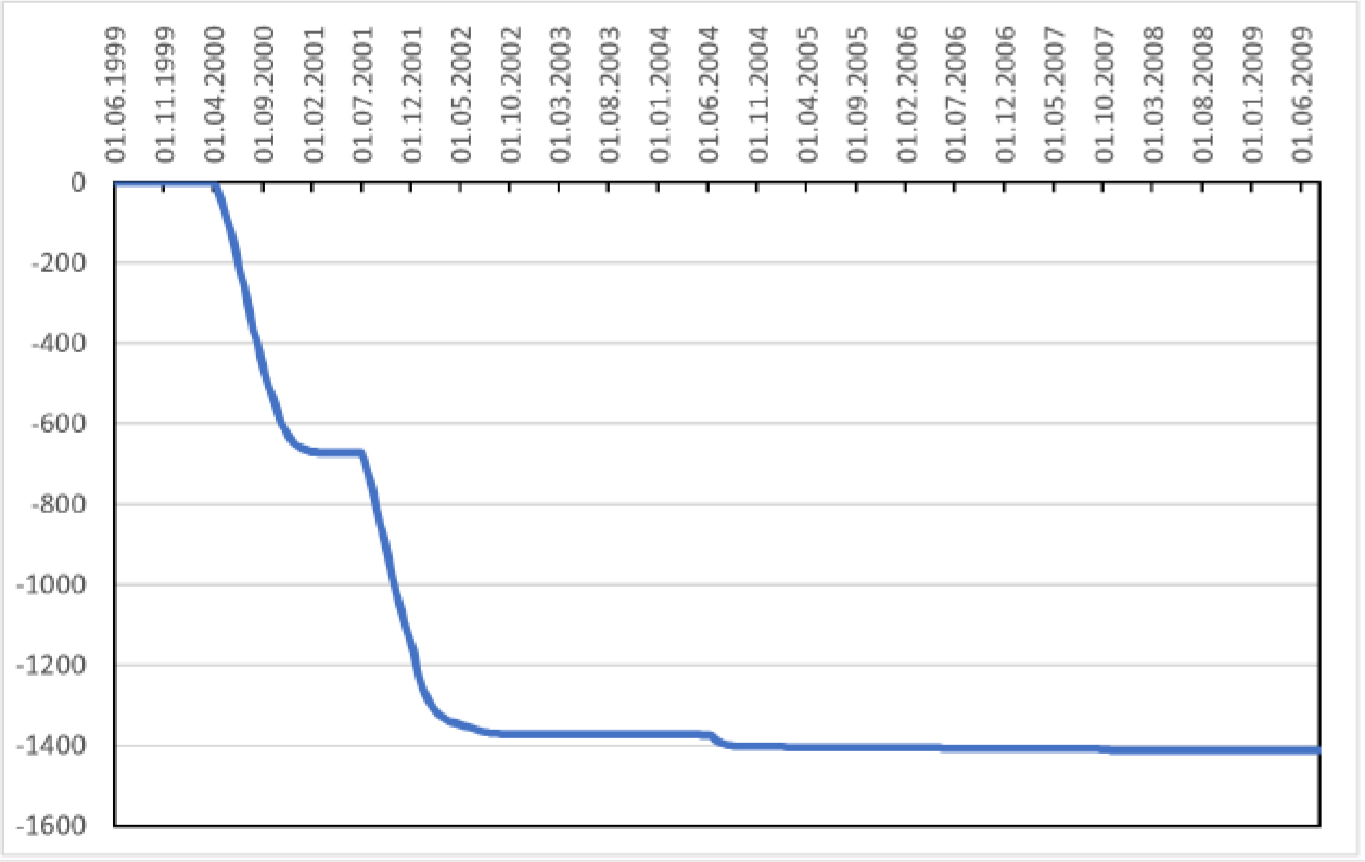
Figure 2.
Graph of the increased subsidence calculated in relation to time according to Knothe’s theory
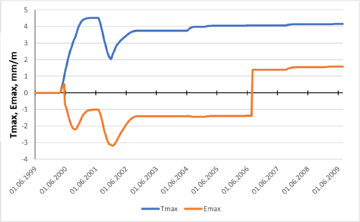
Figure 3.
Graph of the calculated maximum slope (Tmax) and maximum horizontal strain (Emax) in relation to time according to Knothe’s theory
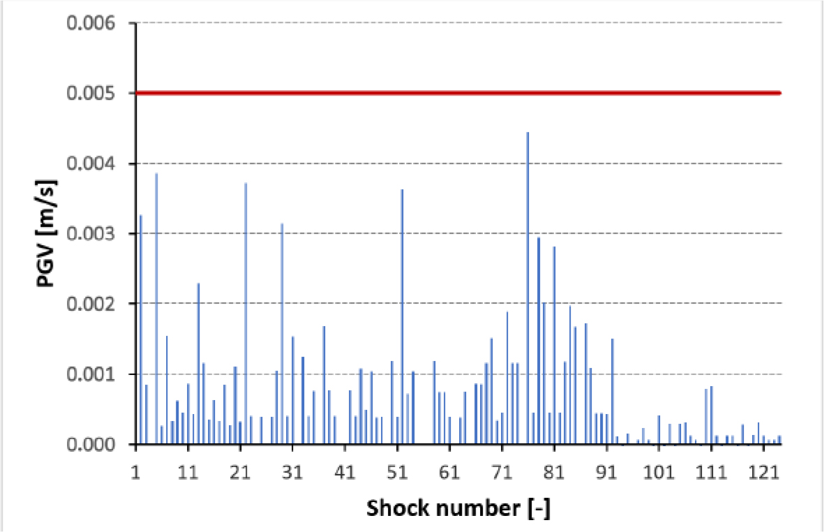
Figure 4.
Calculated PGV values at the property site according to Eq. (3)
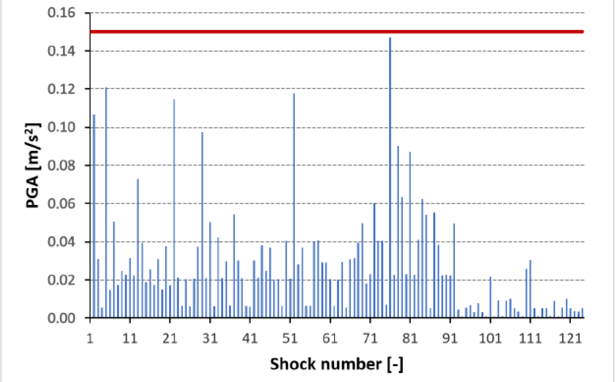
Figure 5.
Calculated PGA values at the property site according to Eq. (2)
Table 2.
Assessment of resistance of selected buildings according to the modified point method
| Identification of the characteristics | Number of points | ||
|---|---|---|---|
| 1. | Building length (m) | up to 15 m | 4 |
| 2. | The shape of the solid | simple building plan, compact solid | 0 |
| 3. | Foundation of the building | at a constant level | 0 |
| 4. | Building subsoil | non-rocky soil with the exception of stony soil | 0 |
| 5. | Building structure | brick strip foundation | 3 |
| basement walls: brick masonry | 1 | ||
| the lowest storey ceiling: arched ceiling on I-beams at f/L < 1/10 | 4 | ||
| lintels: brick flat | 2 | ||
| 6. | Existing protection against mining influence | no protection | 15 |
| 7. | Technical condition of the building1 | natural wear of building: medium | 2 |
| building damage: cracks up to 15 mm and inclination <25 mm/m | 8 | ||
| Total points | 39 | ||
Table 3.
Resistance of buildings to the influence of ground deformation – building qualification category according to the modified point method
| Sum of points n (-) | Permissible horizontal strain of the subsoil εp (mm/m) | Building resistance category |
|---|---|---|
| ≤ 20 | 7.0 – 9.0 | 4 |
| 21–23 24–29 30–33 | 6.0 5.0 4.0 | 3 |
| 34–36 37–43 44–46 | 3.0 2.5 2.0 | 2 |
| 47–49 50–56 57–59 | 1.5 1.0 0.5 | 1 |
| ≥ 60 | ≤ 0.3 | 0 |
Table 4.
Categories of mining area deformation [13]
| Categories of mining area | The values of terrain deformation indicators | ||
|---|---|---|---|
| Inclination T (mm/m) | Radius of curvature R (km) | Horizontal strain ε (mm/m) | |
| 0 | T < 0.5 | |R| > 40 | |ε| < 0.3 |
| I | 0.5 ≤ T < 2.5 | 40 ≥ |R| > 20 | 0.3 ≤ |ε| < 1.5 |
| II | 2.5 ≤ T < 5.0 | 20 ≥ |R| > 12 | 1.5 ≤ |ε| < 3.0 |
| III | 5.0 ≤ T < 10.0 | 12 ≥ |R| > 6 | 3.0 ≤ |ε| < 6.0 |
| IV | 10.0 ≤ T < 15.0 | 6 ≥ |R| > 4 | 6.0 ≤ |ε| < 9.0 |
| V | T ≥ 15.0 | |R| ≤ 4 | |ε| ≥ 9.0 |
Table 5.
Shock cases recorded on the measurement stand and estimated values in the mining forecast
| Date | E (J) | PGA meas. (mm/s2) | PGA est. (mm/s2) | t Ha (s) | PGA meas./PGA est. (-) |
|---|---|---|---|---|---|
| 18.04.2015 | 4.00E+09 | 258 | 230 | 3.90 | 1.1 |
| 05.08.2016 | 4.00E+06 | 459 | 151 | 1.54 | 3.0 |
| 02.01.2017 | 8.00E+06 | 629 | 142 | 1.66 | 4.4 |
| 27.01.2017 | 8.00E+06 | 300 | 143 | 1.55 | 2.1 |
| 21.02.2017 | 2.00E+06 | 313 | 95 | 1.78 | 3.3 |
| 14.03.2017 | 2.00E+06 | 310 | 121 | 1.72 | 2.6 |
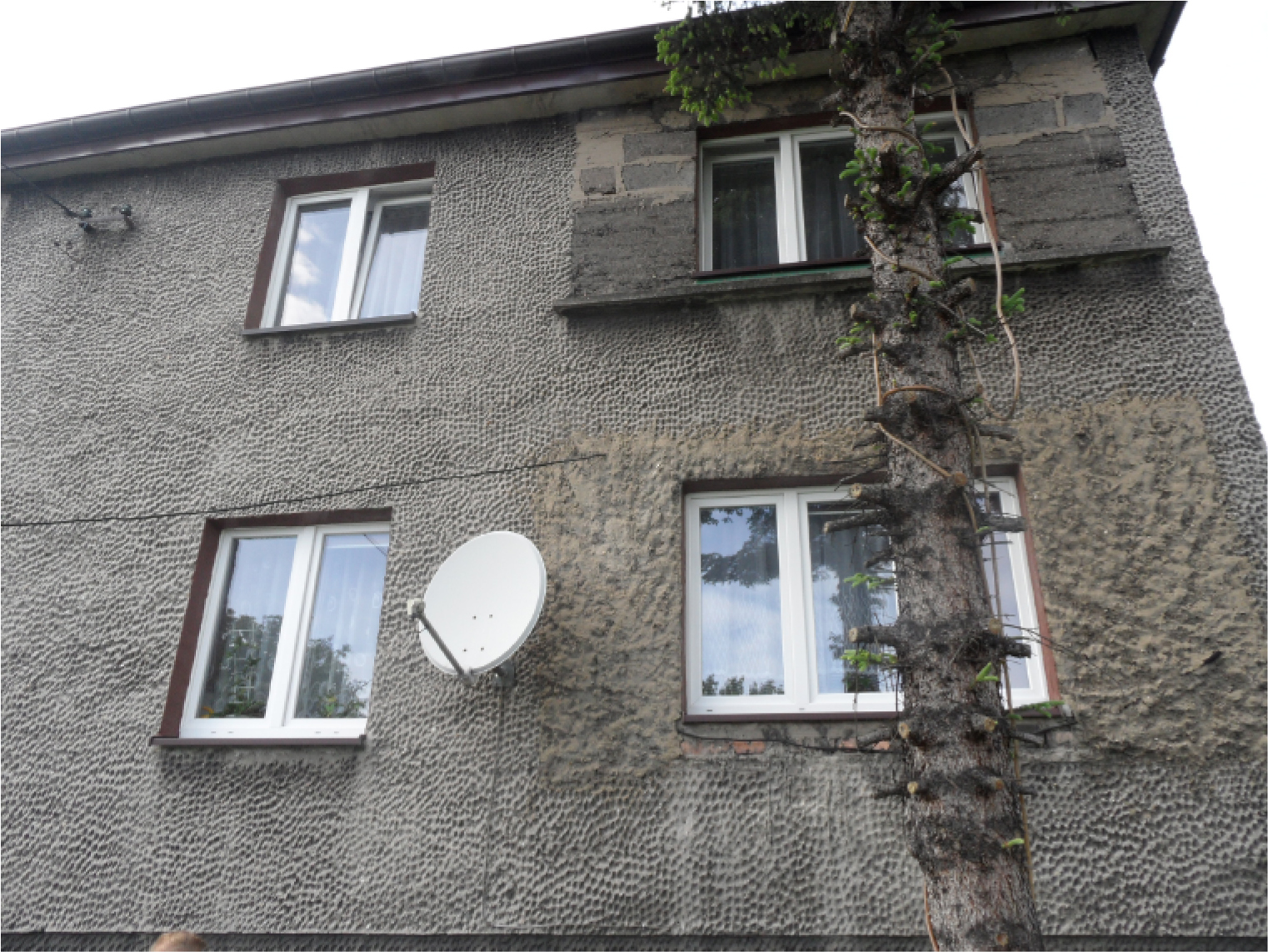
Figure 6.
General view of the southern wall of the building
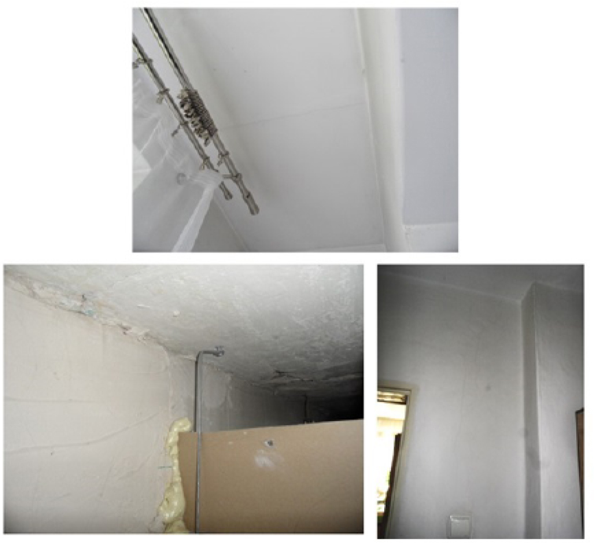
Figure 7.
Cracking of the walls and ceilings inside the building
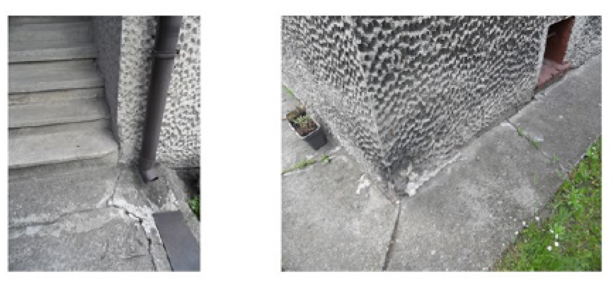
Figure 8.
Cracking of the entrance stairs and the splash apron around the building