
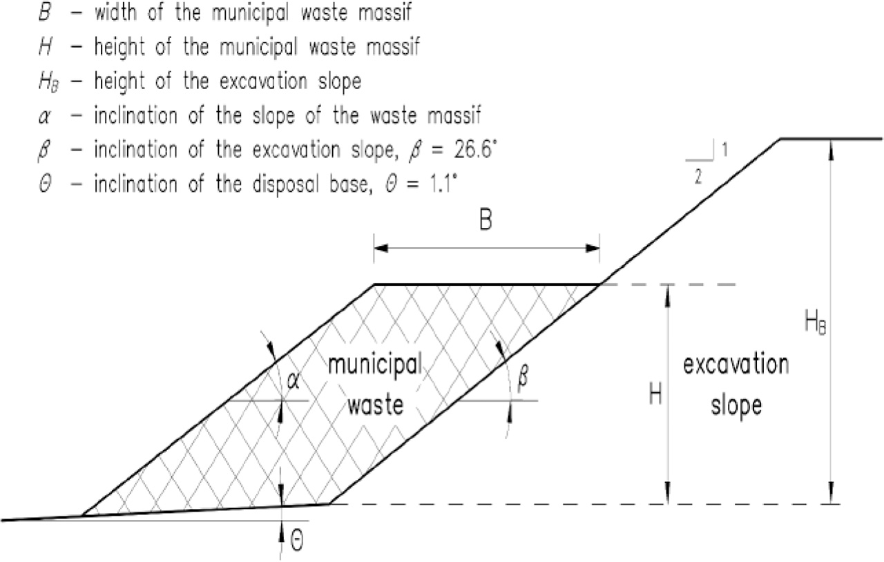
Figure 1.
Scheme of municipal waste storage at the landfill
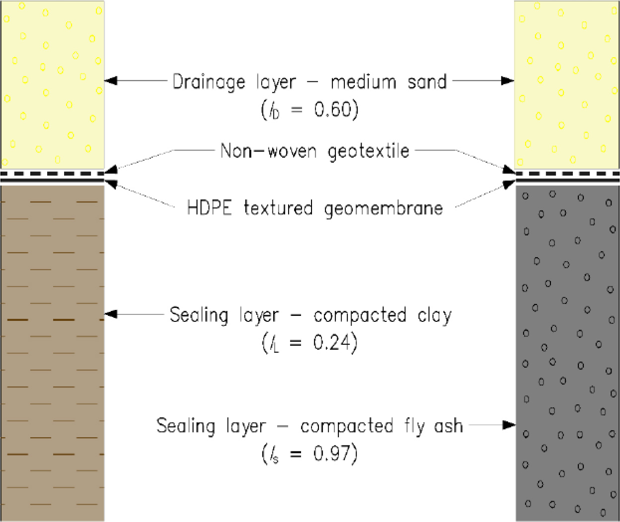
Figure 2.
Cross-section through a single-sealing layer of slope and base of the landfill made of compacted clay or compacted fly ash
Table 1.
Parameters of materials used for calculations of waste landfill stability
| Layer number | Material | γ (kN/m3) | ϕ/δ (°) | c/ca (kPa) |
|---|---|---|---|---|
| I | Municipal waste | 10.20 | 30.0 | 3.0 |
| II | Medium sand ID=0.60 | 16.68 | 33.6 | – |
| III | Medium sand + Non-woven geotextile | 9.02 | 27.0 | 14.0 |
| IV | Non-woven geotextile + Textured geomembrane HDPE | 5.29 | 24.0 | 0.0 |
| V | Textured geomembrane HDPE + Compacted clay | 14.91 | 19.0 | 9.3 |
| VI | Compacted clay IL=0.24 | 20.60 | 17.5 | 30.1 |
[i] Explanation: ID – the density index (the relative density), IL – the plasticity index, γ – the unit weight, ϕ and δ – the internal and interface friction angle, respectively, c and ca – the cohesion and adhesion, respectively.
Table 2.
Parameters of materials used for alternative calculations of waste landfill stability
| Layer number | Material | γ (kN/m3) | ϕ/δ (°) | c/ca (kPa) |
|---|---|---|---|---|
| V | Textured geomembrane HDPE + Compacted fly ash | 11.77 | 12.0 | 10.0 |
| VI | Compacted fly ash R=0.97 | 14.32 | 40.0 | 42.0 |
[i] Explanation: R – the relative compaction (% of maximum compaction)
Table 3.
Percentage utilization for the limit state Λ and factor of safety (F) depending on slope geometry and calculation method for compacted clay as a mineral sealing layer.
| Geometrical parameters | Percentage utilization Λ (%) / factor of safety F (−) determined by the method: | ||||||
|---|---|---|---|---|---|---|---|
| Bishop | Fellenius/Petterson | Spencer | Janbu | Morgenstern-Price | |||
| α=20° | B=10 m | H=5 m | 94.1/1.33 | ||||
| H=10 m | |||||||
| H=30 m | |||||||
| H=50 m | 72.3/1.73 | 73.0/1.71 | 71.6/1.75 | 71.4/1.75 | 71.3/1.75 | ||
| B=50 m | H=5 m | 94.1/1.33 | |||||
| H=10 m | |||||||
| H=30 m | |||||||
| H=50 m | 70.8/1.77 | 72.3/1.73 | 70.8/1.76 | 70.8/1.76 | 70.8/1.76 | ||
| α=25° | B=10 m | H=5 m | 94.1/1.33 | ||||
| H=10 m | |||||||
| H=30 m | |||||||
| H=50 m | 87.7/1.42 | 89.1/1.40 | 87.3/1.43 | 87.2/1.43 | 87.2/1.43 | ||
| B=50 m | H=5 m | 94.1/1.33 | |||||
| H=10 m | |||||||
| H=30 m | |||||||
| H=50 m | 88.8/1.41 | 90.9/1.38 | 88.9/1.41 | 88.9/1.41 | 88.9/1.41 | ||
| α=30° | B=10 m | H=5 m | 94.1/1.33 | ||||
| H=10 m | |||||||
| H=30 m | 97.0/1.29 | 97.9/1.28 | 98.7/1.27 | 98.1/1.27 | 98.4/1.27 | ||
| H=50 m | – | – | – | – | – | ||
| B=50 m | H=5 m | 94.1/1.33 | |||||
| H=10 m | |||||||
| H=30 m | 102.0/1.22 | 105.4/1.19 | 102.1/1.22 | 102.1/1.22 | 102.1/1.22 | ||
| H=50 m | 107.5/1.16 | 110.3/1.13 | 107.6/1.16 | 107.6/1.16 | 107.6/1.16 | ||
| α=45° | B=10 m | H=5 m | 99.5/1.26 | 106.2/1.18 | 99.8/1.25 | 99.8/1.25 | 99.2/1.26 |
| H=10 m | 133.6/0.94 | 137.7/0.91 | 133.1/0.94 | 132.7/0.94 | 132.8/0.94 | ||
| H=30 m | – | – | – | – | – | ||
| H=50 m | – | ||||||
| B=50 m | H=5 m | 105.3/1.19 | 110.4/1.13 | 105.7/1.18 | 105.7/1.18 | 105.2/1.19 | |
| H=10 m | 126.5/0.99 | 132.7/0.94 | 127.0/0.98 | 126.9/0.98 | 127.0/0.98 | ||
| H=30 m | 158.8/0.79 | 165.4/0.76 | 159.2/0.79 | 159.3/0.78 | 159.2/0.79 | ||
| H=50 m | 171.5/0.73 | 178.4/0.70 | 171.9/0.72 | 171.8/0.73 | 171.8/0.73 | ||
Table 4.
Percentage utilization for the limit state (Λ) and factor of safety (F) depending on slope geometry and calculation method for compacted fly ash as a mineral sealing layer
| Geometrical parameters | Percentage utilization Λ (%) / factor of safety F (−) determined by the method: | ||||||
|---|---|---|---|---|---|---|---|
| Bishop | Fellenius/Petterson | Spencer | Janbu | Morgenstern-Price | |||
| α=30° | B=10 m | H=5 m | 94.1/1.33 | ||||
| H=10 m | |||||||
| H=30 m | 97.3/1.28 | 99.7/1.25 | 99.6/1.25 | 99.1/1.26 | 98.4/1.27 | ||
| H=50 m | – | – | – | – | – | ||
| B=50 m | H=5 m | 94.1/1.33 | |||||
| H=10 m | |||||||
| H=30 m | 102.0/1.22 | 105.4/1.19 | 102.1/1.22 | 102.1/1.22 | 102.1/1.22 | ||
| H=50 m | 107.5/1.16 | 110.3/1.13 | 107.6/1.16 | 107.6/1.16 | 107.6/1.16 | ||
| α=45° | B=10 m | H=5 m | 99.5/1.26 | 106.2/1.18 | 99.8/1.25 | 99.8/1.25 | 99.2/1.26 |
| H=10 m | 133.6/0.94 | 137.7/0.91 | 133.1/0.94 | 132.6/0.94 | 132.8/0.94 | ||
| H=30 m | – | – | – | – | – | ||
| H=50 m | – | – | – | – | – | ||
| B=50 m | H=5 m | 105.3/1.19 | 110.4/1.13 | 105.7/1.18 | 105.1/1.19 | 105.2/1.19 | |
| H=10 m | 126.5/0.99 | 132.7/0.94 | 127.0/0.98 | 126.9/0.98 | 127.0/0.98 | ||
| H=30 m | 158.8/0.79 | 165.4/0.76 | 159.2/0.79 | 159.3/0.78 | 159.2/0.79 | ||
| H=50 m | 171.5/0.73 | 178.4/0.70 | 172.4/0.72 | 171.8/0.73 | 171.8/0.73 | ||
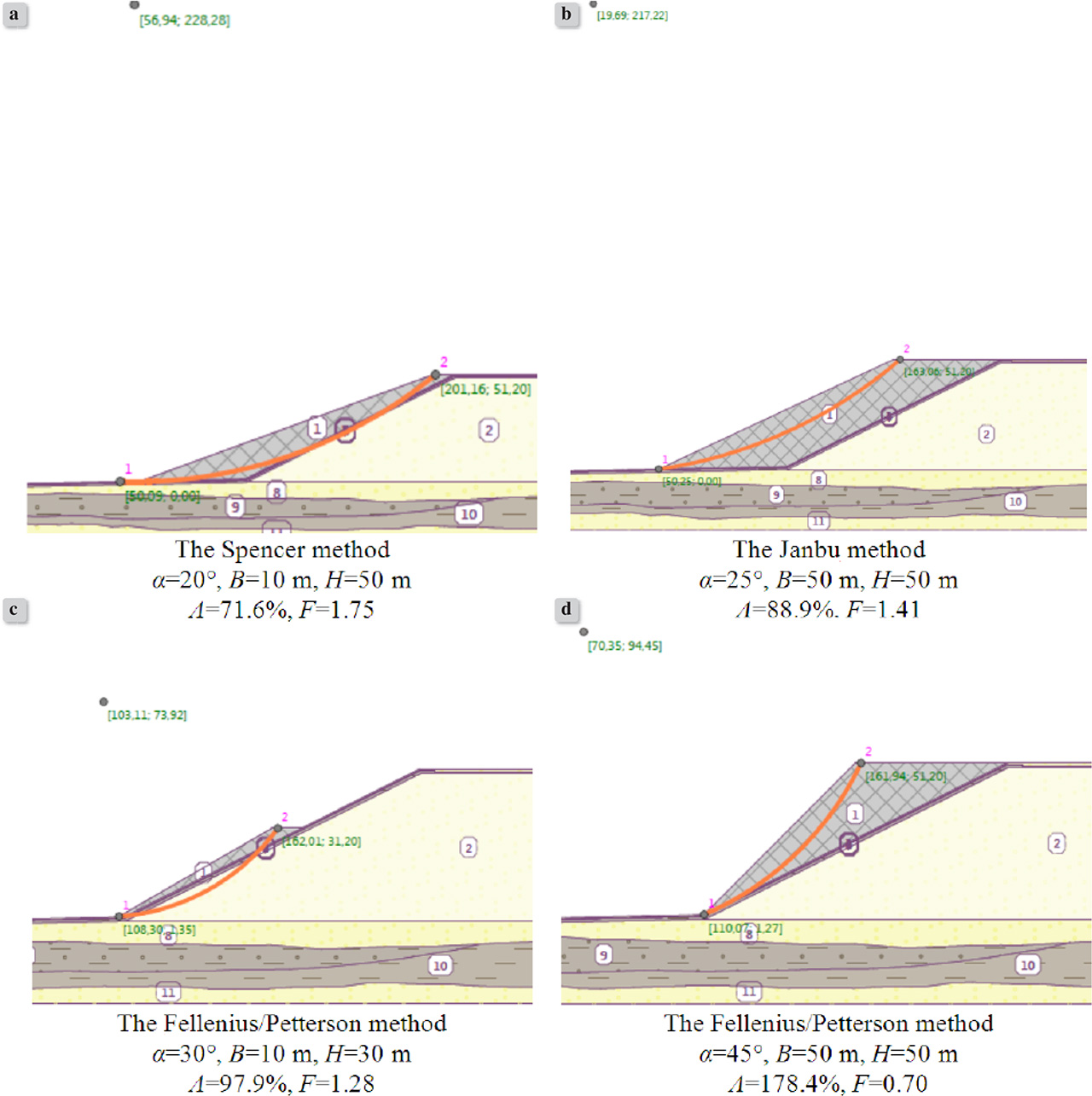
Figure 3.
Examples of slip surfaces generated with the GEO5 program for classic clay mineral sealing layer: a), b), c) the stability of the structure is preserved, d) the stability of the structure was not preserved
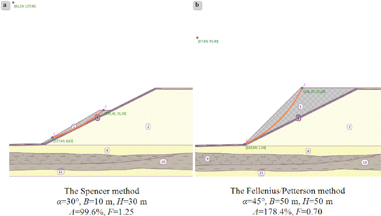
Figure 4.
Examples of slip surfaces generated with the GEO5 program for fly ash as a mineral sealing layer: a) the stability of the structure is preserved, b) the stability of the structure was not preserved