
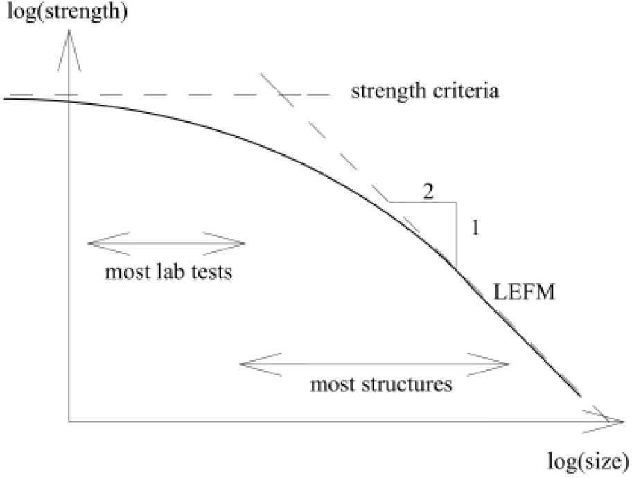
Figure 1.
Size effect on the strength of concrete (adapted from Bazant and Planas [1])
Table 1.
Comparison of the performed experiment and the recommendation of RILEM [20]
| Proportions | RILEM recommendation | Performed experiment |
|---|---|---|
| l/D ratio | >2.5 | 3.33 |
| a0/D ratio | 0.15<a0/D<0.5 | 0.083 |
| notch width | <0.5da (8 mm) | 0.125 da (2 mm) |
| b | >3da (48 mm) | 9.4 da (150 mm) |
| Dmin | <5da (80 mm) | 4.7da (75 mm) |
| Dmax | >10da (160 mm) | 18.75da (300 mm) |
| Dmax/Dmin | ≥4 | 4 |
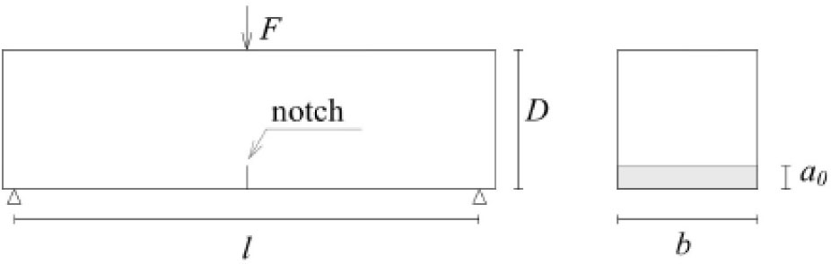
Figure 2.
Specimen dimensions and experimental layout
Table 2.
Dimensions of the test specimens
| Specimen ID | Beam depth (D) [mm] | Span (l) [mm] | Notch depth (a0) [mm] |
|---|---|---|---|
| FRC_S | 75 | 250 | 6.25 |
| FRC_M | 150 | 500 | 12.5 |
| FRC_L | 300 | 1000 | 25 |
Table 3.
Proportions of concrete matrix
| Component | Dosage [kg/m3] |
|---|---|
| Cement | 350 |
| Water | 192 |
| Aggregate 0/4 | 631 |
| Aggregate 4/8 | 685 |
| Aggregate 8/16 | 487 |
| Superplasticizer | 2 |
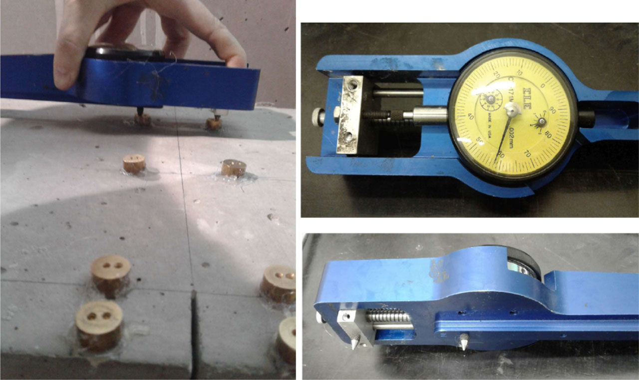
Figure 3.
Measurement of the crack opening
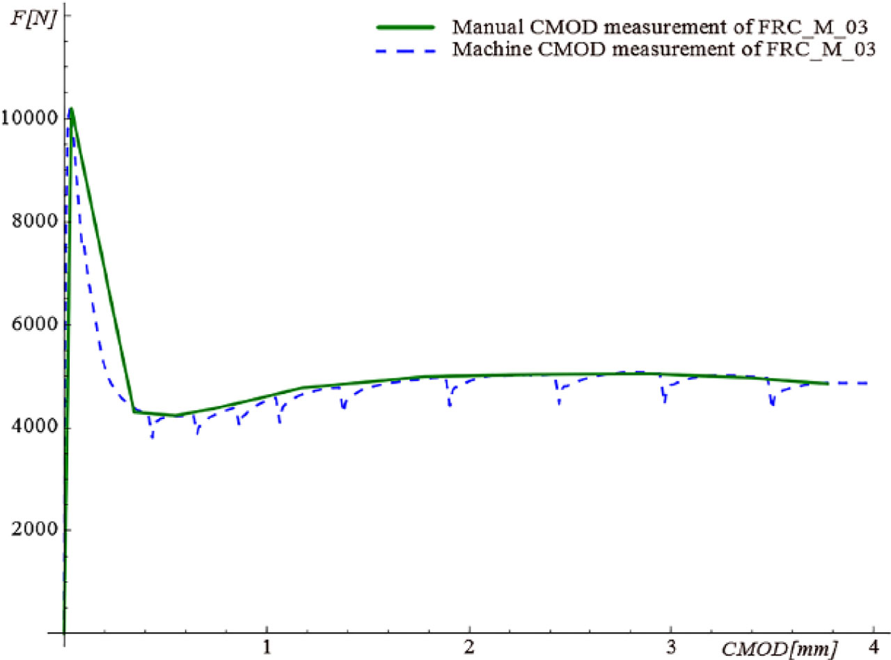
Figure 4.
Comparison of manual and machine CMOD measurement in the case of FRC_M_03
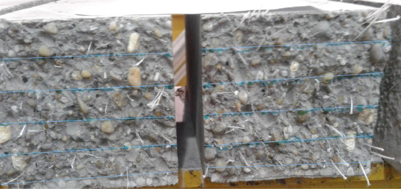
Figure 5.
Cracked cross-sections divided into five zones
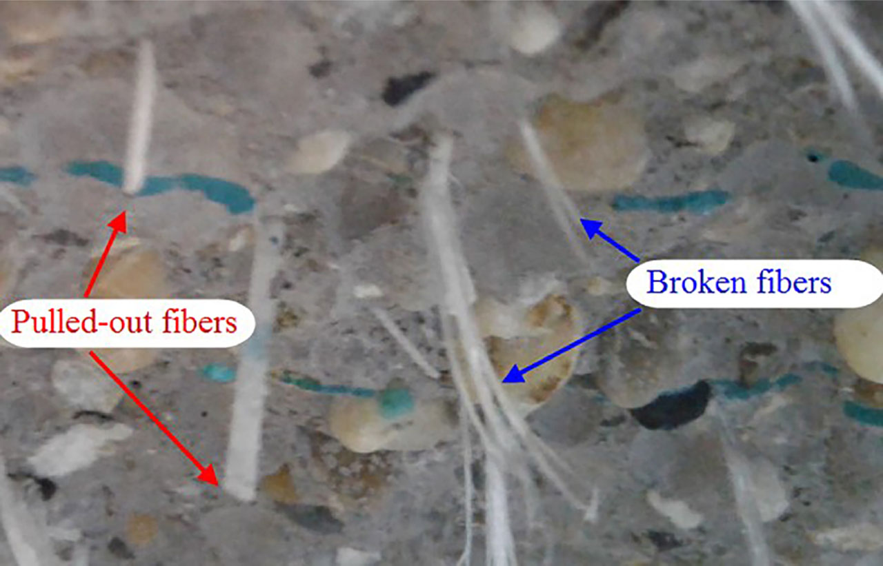
Figure 6.
Appearance of pulled-out and broken fibres
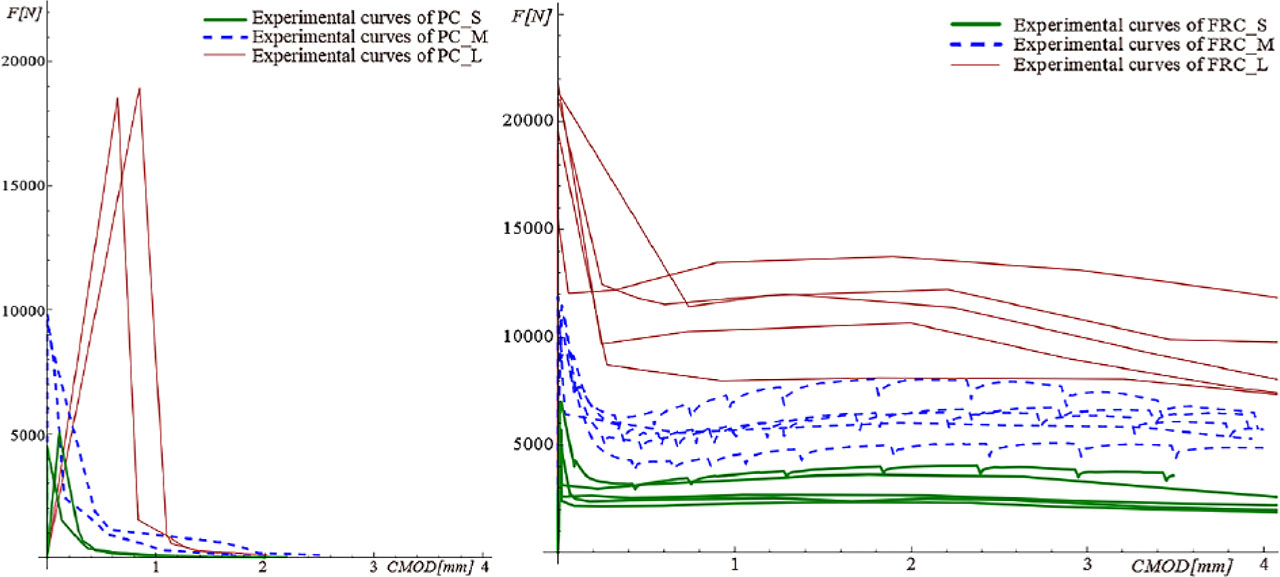
Figure 7.
Experimental F-CMOD results of PC (left) and FRC (right) beams
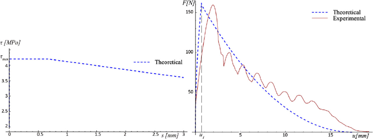
Figure 8.
Experimental and theoretical τ-s and F-u curves of the pulled-out fibres (Reprinted from Tóth and Pluzsik [19])
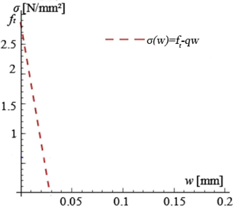
Figure 9.
Softening curve of plain concrete (Reprinted from Tóth and Pluzsik [23])
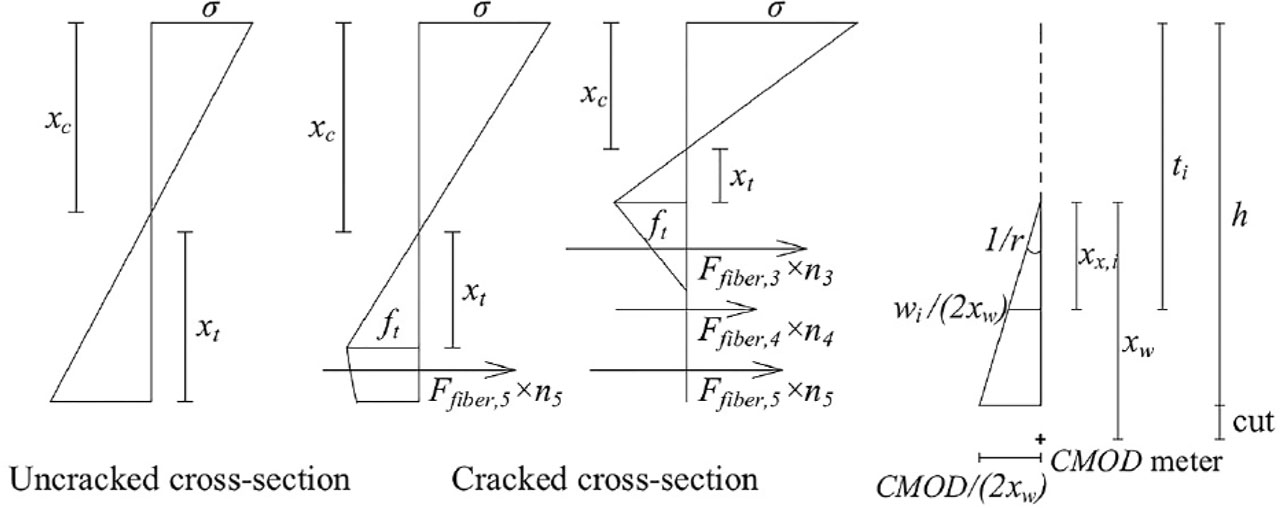
Figure 10.
Stress distribution and distances along the cross-section (Reprinted from Tóth and Pluzsik [19])
Table 4.
Nominal stresses and q values of PC specimens
| Specimen ID | Beam depth (D) [mm] | Nominal stress (σN) [N/mm2] | Average of σN [N/mm2] | Deviation of σN [%] | Slope of the softening curve (q) [N/mm3] |
|---|---|---|---|---|---|
| PC_S_06 | 75 | 2.73 | 2.9 | −5.9 | 15 |
| PC_S_07 | 75 | 3.07 | 5.9 | ||
| PC_M_06 | 150 | 2.84 | 2.81 | 1.2 | 15 |
| PC_M_07 | 150 | 2.77 | −1.2 | ||
| PC_L_06 | 300 | 2.50 | 2.48 | 1 | 15 |
| PC_L_07 | 300 | 2.45 | −1 |
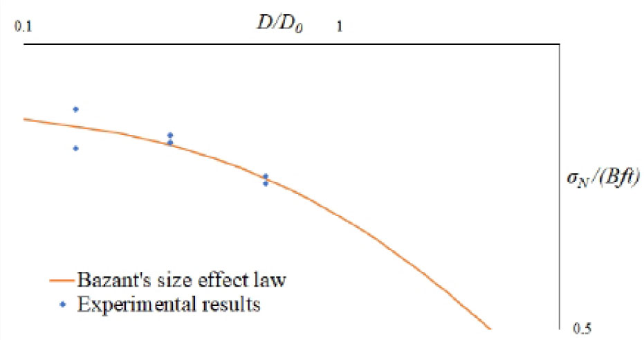
Figure 11.
Size effect of Bazant compared to experimental results of PC
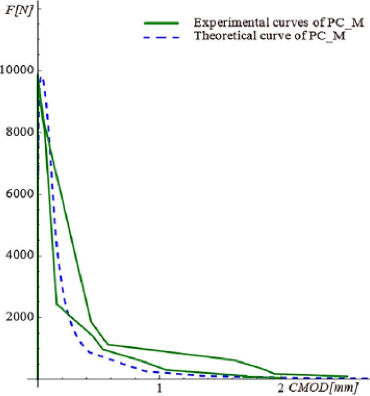
Figure 12.
Experimental and theoretical F-CMOD curves of PC_M (q = 15 N/mm3)
Table 5.
Nominal stresses and τmax values of FRC specimens
| Specimen ID | Nominal stress (σN) [N/mm2] | Average of σN2 [N/mm2] | τmax [N/mm2] | Average of τmax [N/mm2] | Deviation of τmax [%] | Pulled-out fibres [pcs] | Broken fibres [pcs] | Rate of pulled-out fibres [%] |
|---|---|---|---|---|---|---|---|---|
| FRC_S_01 | 3.29 | 3.47 | 3.4 | 3.16 | 8% | 47 | 7 | 87% |
| FRC_S_02 | 3.47 | 2.4 | −24% | 51 | 10 | 84% | ||
| FRC_S_03 | 3.34 | 3.0 | −5% | 52 | 10 | 84% | ||
| FRC_S_04 | 4.25 | 3.4 | 8% | 30 | 22 | 58% | ||
| FRC_S_05 | 3 | 3.6 | 14% | 39 | 13 | 75% | ||
| FRC_M_01 | 3.43 | 3.10 | 3.6 | 3.64 | −1% | 82 | 26 | 76% |
| FRC_M_02 | 2.67 | 3.6 | −1% | 87 | 26 | 77% | ||
| FRC_M_03 | 2.94 | 3.4 | −7% | 70 | 35 | 67% | ||
| FRC_M_04 | 3.18 | 3.6 | −1% | 83 | 42 | 66% | ||
| FRC_M_05 | 3.3 | 4.0 | 10% | 108 | 32 | 77% | ||
| FRC_L_01 | 2.58 | 2.71 | 2.6 | 3.52 | −26% | 179 | 15 | 92% |
| FRC_L_02 | 2.83 | 3.6 | −2% | 179 | 20 | 90% | ||
| FRC_L_03 | 2.88 | 4.4 | 25% | 119 | 35 | 77% | ||
| FRC_L_04 | 2.47 | 3.8 | 8% | 160 | 36 | 82% | ||
| FRC_L_05 | 2.79 | 3.2 | −9% | 159 | 24 | 87% |
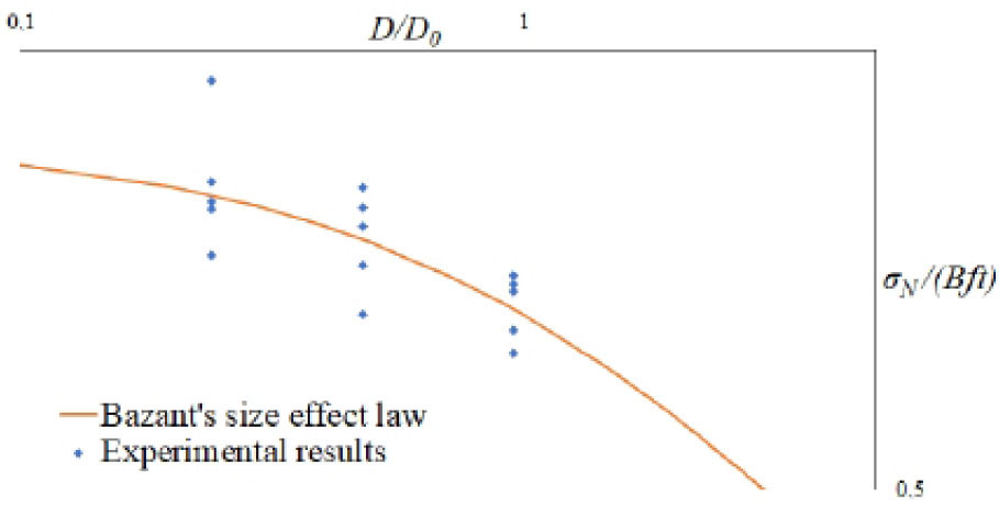
Figure 13.
Size effect of Bazant compared to experimental results of FRC
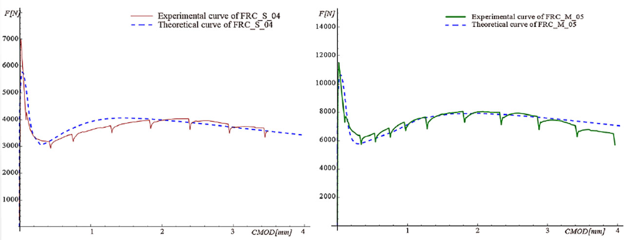
Figure 14.
Experimental and theoretical F-CMOD curves of FRC_S_04 (left: q = 15 N/mm3, τmax = 3.4 N/mm2) and FRC_M_05 (right: q = 15 N/mm3, τmax = 4 N/mm2)
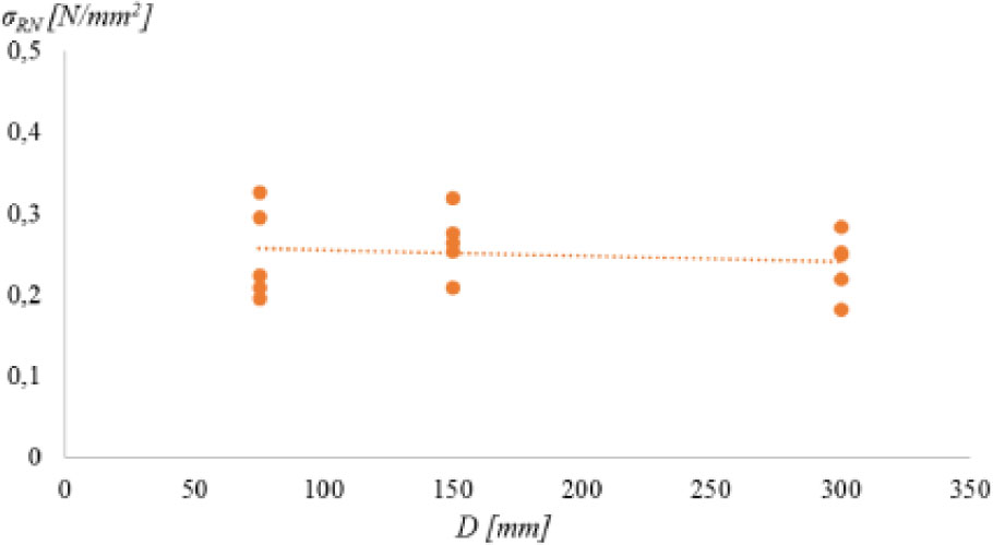
Figure 15.
Residual nominal strength (σRN) depending on the beam depth (D)