
Table 1
Proximate and ultimate analyses of PMSW
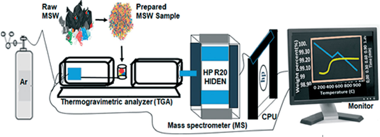
Figure 1
TGA-MS setup for pyrolysis of the PMSW
Table 2
Representative gas species evolved and key ion fragments according to their m/z ratio
| Representative species | Ion fragments | m/z ratio |
|---|---|---|
| Hydrogen | H2+ | 2 |
| Methane | CH3+ | 15 |
| Water | H2O+ | 18 |
| Carbon monoxide | CO+ | 28 |
| Ethane | C2H+2 | 28 |
| Argon | Ar+ | 40 |
| Carbon dioxide | CO2+ | 44 |
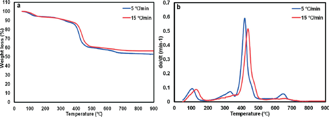
Figure 2
Thermogravimetric (TG) and Differential thermo-gravimetric (DTG) (b) profiles of pyrolysis of PMSW
Table 3
Temperature characteristics of the conversion phases obtained from pyrolysis of PMSW
| Regime | Heating rate (°C/min) | Stage 1 | Stage 2 | Stage 3 | Stage 4 | ||||||||
|---|---|---|---|---|---|---|---|---|---|---|---|---|---|
| Ti (°C) | Tmax (°C) | Tf (°C) | Ti (°C) | Tmax (°C) | Tf (°C) | Ti (°C) | Tmax (°C) | Tf (°C) | Ti (°C) | Tmax (°C) | Tf (°C) | ||
| Pyrolysis | 5 | 50 | 113 | 180 | 230 | 334 | 360 | 360 | 419 | 500 | 605 | 652 | 690 |
| 15 | 50 | 133 | 182 | 230 | 438 | 515 | - | - | - | - | - | - | |
[i] Note: Ti is the initial temperature of each phase; Tmax is the maximum (at peak) temperature of each phase; Tf is the final temperature of each phase
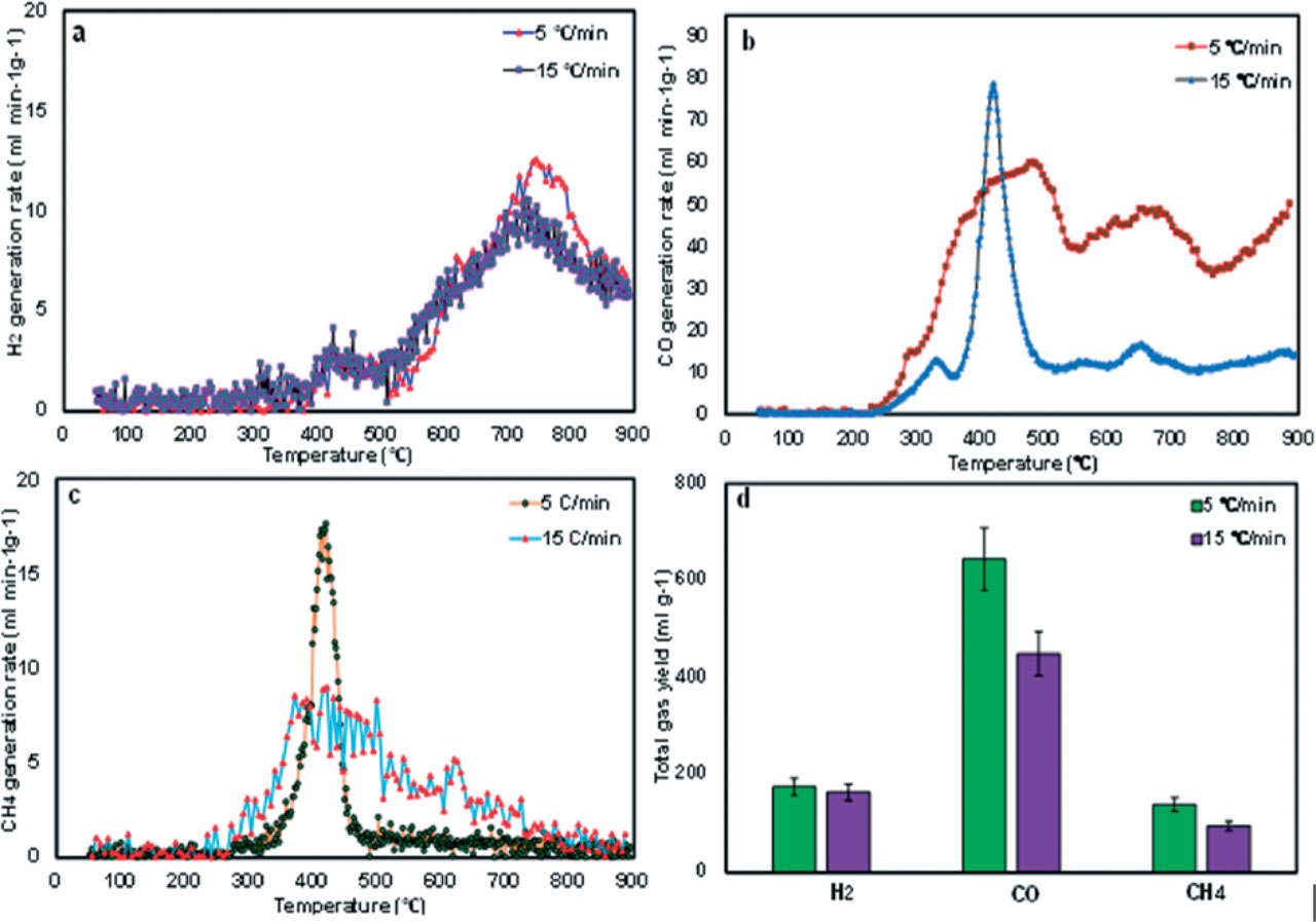
Figure 3
The generation rates of (a) H2, (b) CO, and (c) CH4, and (d) their total yields obtained from pyrolysis of PMSW at 5 and 15°C/min.
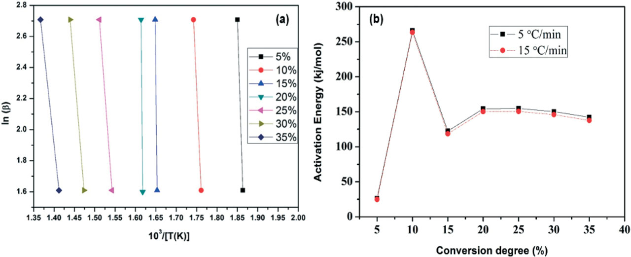
Figure 4
(a) Fitting curves and (b) plots of activation energy obtained from the pyrolysis of PMSW at different conversion degrees at heating rates of 5 and 15°C/min.
Table 4
Kinetic parameters at different conversion rates at heating rates of 5 and 15°C/min
| Environment | Heating rate (°C/min) | Conversion degree (α) | Activation energy (kJmol−1) | R2 |
|---|---|---|---|---|
| Pyrolysis | 5 | 5 | 26.2165 | 0.9972 |
| 10 | 266.1419 | 0.9722 | ||
| 15 | 122.3063 | 0.9967 | ||
| 20 | 154.2912 | 0.9839 | ||
| 25 | 154.6809 | 0.9849 | ||
| 30 | 150.212 | 0.9941 | ||
| 35 | 142.1621 | 0.9932 | ||
| 15 | 5 | 24.89866 | 0.9983 | |
| 10 | 263.3126 | 0.9701 | ||
| 15 | 118.488 | 0.9949 | ||
| 20 | 150.2019 | 0.9811 | ||
| 25 | 150.4602 | 0.9935 | ||
| 30 | 145.8795 | 0.9922 | ||
| 35 | 137.6665 | 0.9917 |
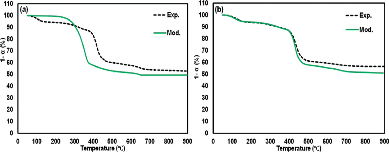
Figure 5
Experimental (dotted) and model (solid) lines through the FWO method were (a) and (b) show the pyrolysis at 5 and 15°C/min, respectively