

A reinforced concrete (RC) deep beam is one of the structural elements used in different structures, such as bridge bents, bridge girders, pile caps, and offshore structures. The shear deformation dominates the behavior of this element. Therefore, deep beams should be designed to have an acceptable level of shear strength by providing sufficient shear reinforcement. According to ACI 318-2014 (American Concrete Institute [ACI], 2014), the deep beam span should not exceed four times the overall depth. In addition, the shear span should be equal to or less than twice the beam depth. Different parameters play a significant role in controlling the behavior of this type of structure, such as compressive strength of concrete, the shear span to depth ratio, the reinforcement ratio, and the arrangement of shear reinforcement.
Many studies have been conducted to investigate the role of the shear reinforcement type in reinforced concrete (RC) beams (Colajanni et al., 2014; Ombres, 2015; Ammash, 2017). It was shown experimentally that the shear strength of RC beams increases with the use of additional horizontal and independent bent-up bars (Hamid, 2005). A study was conducted to investigate different types of shear reinforcement that can be employed in RC beams. The obtained results showed that, when swimmer bars were used as shear reinforcement, an improvement was observed in the shear strength of RC beams compared with traditional stirrups (Al-Nasra & Asha, 2013).
Aziz and Yaseen (2013) studied the effect of the type and position of shear reinforcement on the behavior of high-strength deep beams. They showed experimentally that deep beams with a combination of inclined and vertical web reinforcement exhibited greater strength capacity than those with other shear reinforcement arrangements (Aziz & Yaseen, 2013). Ismail et al. (2017) conducted an experimental program to study the effect of different parameters on the behavior of RC deep beams, such as concrete strength, shear span to effective depth ratio, and shear reinforcement. They concluded that the concrete strength, the shear span-depth ratio, and the shear reinforcement need to be included in the current strength reduction factors used in design guidelines for inclined concrete struts (Ismail et al., 2017).
Self-compacting concrete (SCC) is considered an innovative solution for overcoming the challenges related to reinforcement congestion in deep beams. This type of concrete can spread into place, fill formwork, and encapsulate reinforcement due to its highly flowable properties, which eliminate the need for mechanical vibration and maintain homogeneity (EFNARC, 2005; Alkhattat & Al-Ramahee, 2021). SCC is suitable for deep beam applications due to its superior fresh properties, such as high deformability, adequate viscosity to resist segregation, and excellent passing ability through tight reinforcement spacing (Khayat & Mitchell, 2009). It was shown that the SCC deep beams exhibit comparable or superior structural performance compared with traditional concrete deep beams. SCC deep beams show improved concrete quality in congested regions, better bond characteristics between concrete and reinforcement, and enhanced construction efficiency (Hakeem et al., 2024).
Steel plates have recently been considered as an alternative shear reinforcement solution to reduce congestion while maintaining or enhancing structural performance. They can be configured in many forms, such as perforated thin plates, solid plates, externally bonded plates, and internally embedded plate assemblies (Mhalhal & Al-Gasham, 2018). Different studies have shown varying degrees of success in the use of steel plate reinforcement systems. Chai et al. (2023) studied the use of perforated thin mild steel plates in deep beams and found that 2.0 mm plates with optimal perforation patterns achieved increases in the capacity of approximately 3% compared to the traditional reinforcement. Hamoda et al. (2024) have reported a 129% to 175% increase in ultimate shear capacity when externally bonded stainless-steel plates were used. The range of this increase depended on plate thickness and anchorage detailing.
The most common criterion for replacing traditional reinforcement with an alternative system is based on cross-sectional area equivalency, in which the total area of the traditional reinforcement is matched to the total area of the alternative reinforcement (Su et al., 2009). However, this criterion may not accurately represent the actual force transfer mechanisms in deep beams, where the strut-and-tie behavior and stress distribution differ significantly from those predicted by shallow beam theory. A rational approach would be based on the equivalency of the actual forces that shear reinforcement can carry, considering the specific load paths and stress field in deep beams according to strut-and-tie analysis and ACI 318 provisions. However, the validation of force-based procedure for designing steel plate replacement for shear reinforcement in deep beams is limited, despite the theoretical advantages of force-based equivalency. Moreover, most research has focused on replacing either the web reinforcement (stirrups) or the longitudinal skin reinforcement with steel plates, but studies have examined the simultaneous replacement of both reinforcement types, particularly in the SCC deep beams (Ibrahim et al., 2018; Qaddoory et al., 2021). Furthermore, there is a lack of experimental data on the effect of specific plate thickness on the comprehensive structural performance of SCC deep beams.
This study investigates an innovative approach for SCC deep beams by replacing, based on equivalency, both conventional vertical stirrups and longitudinal skin reinforcement with steel plates of varying thicknesses. Unlike previous studies that employed the area equivalency method, this study employs a force-based equivalency approach, in which the required force capacity of the traditional shear reinforcement is calculated based on strut-and-tie analysis and ACI 318 design provisions, and then used as the basis for determining the appropriate steel plate width replacement. Steel plates with different thicknesses were used (2 mm, 3 mm, and 4 mm) in this study as both vertical and longitudinal reinforcement to investigate the effect of these thicknesses on the structural performance of SCC deep beams.
The experimental program in this research consisted of manufacturing and testing seven self-compacting reinforced concrete deep beams. The dimensions of all specimens were 125 mm (width) and 400 mm (height) with a total length of 1,100 mm and 1,000 mm between supports length. The first specimen was considered a control specimen, where it was reinforced with conventional flexural and shear reinforcement. The control specimen (DB-control) was longitudinally reinforced with 4ø16 mm at bottom and 2ø10 mm at top. Also, it reinforced with 4ø10 mm for skin reinforcement and ø10 mm @ 100 mm c/c web reinforcement as shown in Figure 1. The remaining six specimens were divided into two groups with three specimens for each group. In the first group, comprising three deep beams (DB-web-2, DB-web-3, and DB-web-4), the web reinforcement was replaced with steel plates with a smooth surface finish and varying thicknesses (2 mm, 3 mm, and 4 mm) for each specimen, while the longitudinal and skin reinforcement were kept the same as in the control specimen. The width of each plate was determined based on the force transfer equivalency as 39 mm, 26 mm, and 19.5 mm for the 2 mm, 3 mm, and 4 mm plates’ thickness, respectively. The details of the first group are shown in Figure 2 and Table 1. In the second group, comprising three specimens (DB-skn-2, DB-skn-3, and DB-skn-4), the skin reinforcement was also replaced by steel plates with smooth surface finish and a thicknesses of 2 mm, 3 mm, and 4 mm for each specimen, while the longitudinal and web reinforcement were kept the same as the control specimen. The width of each plate was calculated based on the same criteria to be 39 mm, 26 mm, and 19.5 mm for the 2 mm, 3 mm, and 4 mm plates’ thicknesses, respectively. The details of skin reinforcement for this group were shown in Figure 3 and Table 1. All plate reinforcement, whether used as web or skin reinforcement, was tied to the traditional reinforcement using steel wire (binding wire) prior to casting to ensure proper positioning and mechanical connection within the concrete.
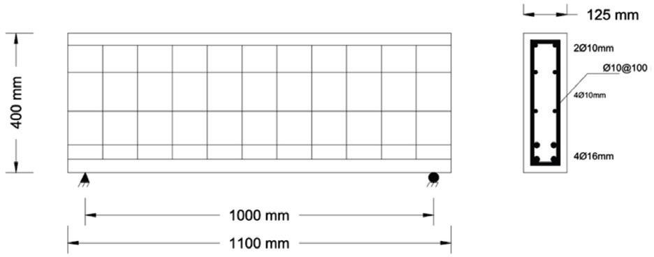
Details of the control self-compacting concrete deep beam
Source: own work.
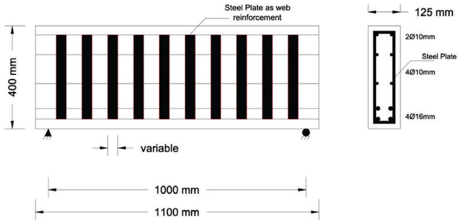
Details of self-compacting concrete deep beam with steel plate as web reinforcement
Source: own work.
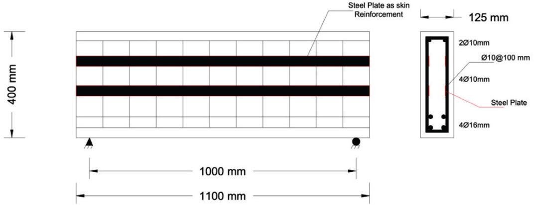
Details of self-compacting concrete deep beam with steel plate as skin reinforcement
Source: own work.
Reinforcement details of self-compacting concrete deep beams
| Beam ID | Group | Longitudinal reinforcement | Web reinforcement | Skin reinforcement | Steel plate width [mm] |
|---|---|---|---|---|---|
| DB-control | control | ø10 mm @ 100 | 4ø10 mm | – | |
| DB-web-2 | 1 | top 2ø10 mm | 2 mm steel plate | 4ø10 mm | 39 |
| DB-web-3 | 3 mm steel plate | 4ø10 mm | 26 | ||
| DB-web-4 | 4 mm steel plate | 4ø10 mm | 19.5 | ||
| DB-skn-2 | 2 | bottom 4ø16 mm | ø10 mm @ 100 | 2 mm steel plate | 39 |
| DB-skn-3 | ø10 mm @ 100 | 3 mm steel plate | 26 | ||
| DB-skn-4 | ø10 mm @ 100 | 4 mm steel plate | 19.5 |
Source: own work.
To ensure the concrete could spread in place, fill the formwork, and fill the gaps between plates, SCC was used in all specimens in this study. Different materials were used in this research, such as portland cement, fine and coarse aggregates, powder, superplasticizer, and steel plates. The proportions of the SCC mix were as follows: 446 kg·m−3 of cement, 759 kg·m−3 of fine aggregate, 831 kg·m−3 of coarse aggregate, 0.12 kg·m−3 of superplasticizer, and 132 kg·m−3 of limestone powder. The compressive strength at the age of 28 days for the SCC mixes used in the deep beams was determined to be 35 MPa in accordance with ASTM C192/C192M-19 (ASTM International [ASTM], 2019). The mechanical properties of all reinforcement and steel plates are shown in Table 2. The tensile test was performed in accordance with ASTM-A370 (ASTM, 2016) and ASTM A615/A615M-20 (ASTM, 2020). All beams were tested under a four-point loading configuration, resulting in a shear span of approximately 333 mm and a shear span-to-effective depth ratio of approximately 1, as shown in Figure 4.
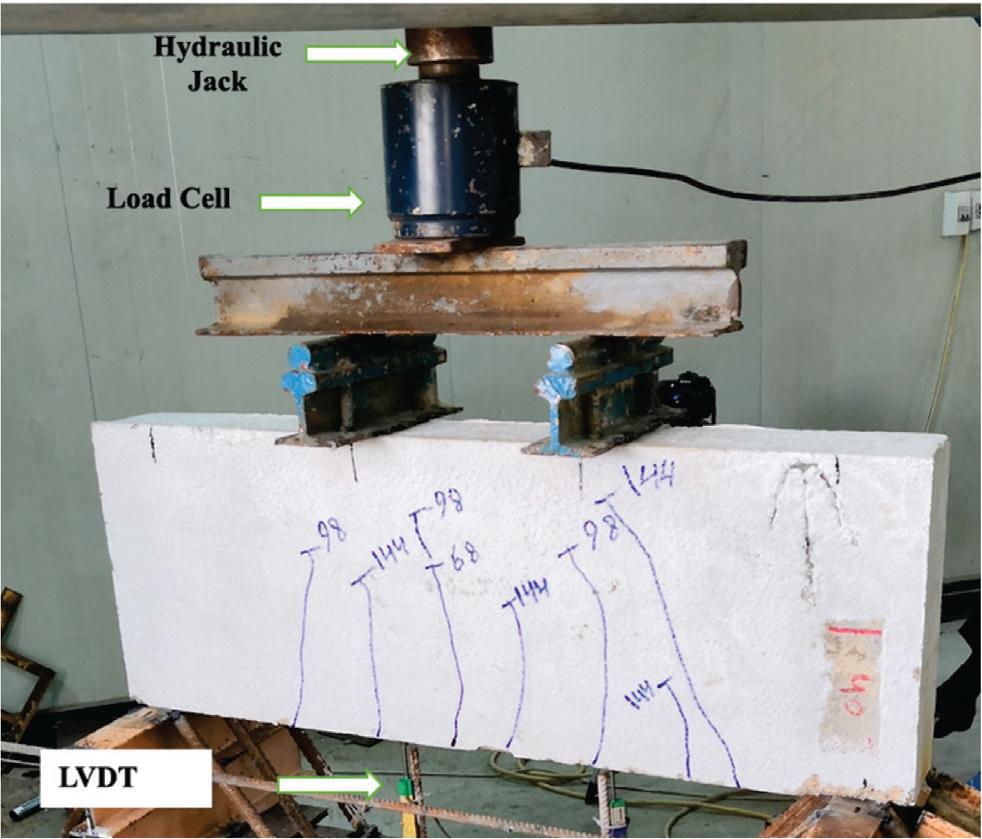
Universal testing machine
Source: own work.
Mechanical properties of steel bars and plates
| Property | ø10 | ø16 | 2 mm steel plate | 3 mm steel plate | 4 mm steel plate |
|---|---|---|---|---|---|
| Yield strength [N·mm−2] | 520 | 563 | 390 | 320 | 250 |
| Tensile strength [N·mm−2] | 610 | 682.94 | 440 | 380 | 340 |
Source: own work.
All specimens were initially cracked at a constant moment zone between loading points. The first crack was recorded in each beam at loads ranging from 40–60 kN, which represents 6–19% of the ultimate load of the SCC deep beams. With an increase in the applied load, inclined shear crack in the shear span zone has started to develop, while the existing flexural cracks propagated toward the compression zone and the applied load. Two failure modes were observed, as shown in Table 3.
Summary of test results
| Beam ID | First crack load [kN] | Ultimate load [kN] | (Pu–Pu control)/ /(Pu control) [%] | Failure mode |
|---|---|---|---|---|
| DB-control | 50 | 425 | 1 | strut compression failure |
| DB-web-2 | 55 | 312 | -26 | diagonal splitting failure |
| DB-web-3 | 55 | 344 | -19 | diagonal splitting failure |
| DB-web-4 | 40 | 470 | 11 | strut compression failure |
| DB-skn-2 | 60 | 355 | -16 | diagonal splitting failure |
| DB-skn-3 | 50 | 418 | -2 | diagonal splitting failure |
| DB-skn-4 | 40 | 432 | 2 | diagonal splitting failure |
Source: own work.
The first one was the strut compression failure, observed in the control specimen and the DB-web-4 specimen. In these beams, the load was transferred through a path between the shear span area between the support and the point of loading. The second failure mode was a diagonal splitting failure in the remaining specimens. In this mode, the diagonal cracks propagated and extended in the shear span area between the support and the loading point. Examples of failure modes are shown in Figure 5.
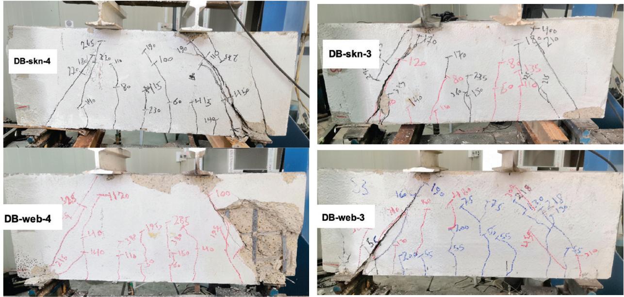
Samples of failure modes in self-compacting concrete deep beams
Source: own work.
The load versus mid-span displacement relationship curves are shown in Figures 6 and 7. These figures show comparison between the control specimen and the specimens in Group 1 (steel plates as web reinforcement) and Group 2 (steel plates as skin reinforcement), respectively. It can be seen from these figures that all specimens with steel plates as web and skin reinforcement had the same initial stiffness. This attribute can be related to the force-based equivalency method that was used in this research. However, Figures 6 and 7 show some differences in the ultimate load capacity compared to the control specimen. For beams with steel plates as web reinforcement, the ultimate load for the beam with a 4 mm plate was 470 kN, which exceeded the ultimate load of the control beam by 11%. While for the beam with a 2 mm steel plate, a reduction in the ultimate load capacity of about 26% was recorded compared to the control specimen. For the beam with a 3 mm steel plate, the peak load decreased by 19% when compared to the control specimen. The observation of lower ultimate load-carrying capacity of the specimen with a 2 mm plate thickness compared to other specimens can be related to the reduced confinement effect provided by plates with lower flexural rigidity and the observed bond loss at the concrete-steel interface, especially over a larger contact surface, despite the increased contact area.
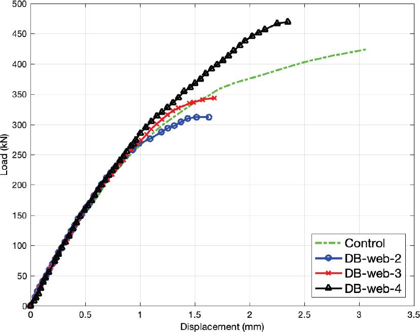
Load–displacement curve comparison for the equivalent steel plate as web reinforcement
Source: own work.
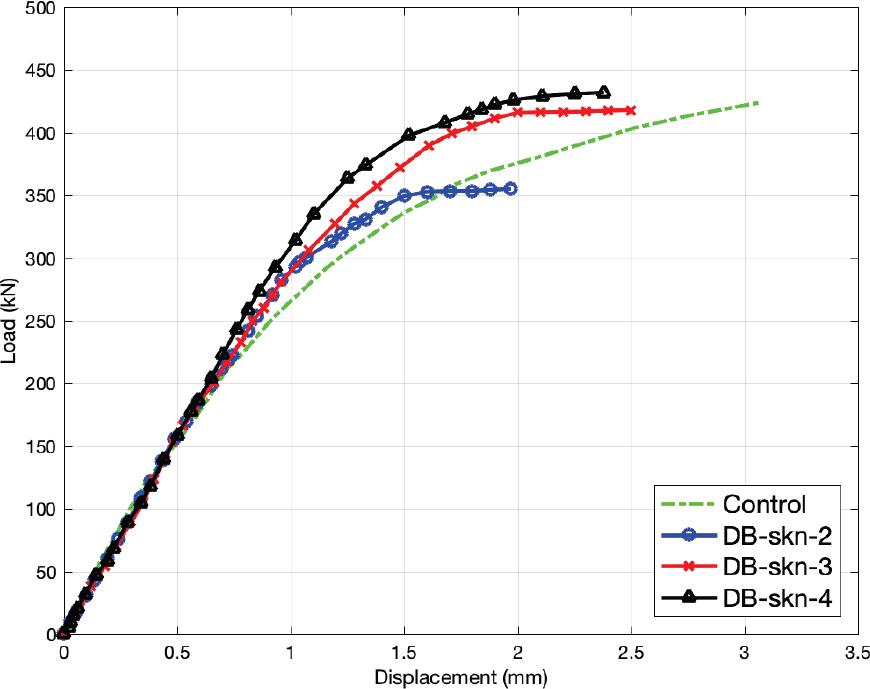
Load–displacement curve comparison for the equivalent steel plate as skin reinforcement
Source: own work.
For specimens with steel plates as skin reinforcement, more comparable results to the control beam in terms of ultimate load were achieved. The ultimate load for the beam with a 2 mm steel plate was 355 kN, which is less than the control beam’s ultimate load by 16%. Moreover, the ultimate load for 3 mm and 4 mm steel plate beams was 418 kN and 432 kN, which represent 2% decrease and 2% increase compared to the control beam, respectively. Furthermore, it was shown that specimens DB-web-4 mm and DB-skn-4, compared to the control beam and beams with 2 mm and 3 mm, showed fewer cracks. In addition, these cracks were restricted and did not widen significantly. For these two specimens’ reinforcement, the steel plates provide more confinement, which delayed the initiation of the first cracks and noticeably enhanced the failure loads compared with the other specimens. It is worth mentioning that local buckling of the steel plate was not observed in any specimens, as full concrete encasement provided continuous lateral restraint to the plates, significantly inhibiting out-of-plane deformation.
The numerical simulation was performed using the ABAQUS/Standard package to model and study the structural behavior of the adopted beams. The outcomes of this simulation were compared with and validated against the corresponding experimental results. A three-dimensional finite element model (FEM) was created in which concrete was modeled using an eight-node linear brick element with reduced integration (C3D8R), and traditional steel reinforcement was modeled using a two-node linear truss element (T3D2). Moreover, the steel plates were represented using S4R shell elements due to their thin-walled nature, as the thicknesses were significantly smaller compared to the other plate dimensions. The nonlinear behavior of SCC was simulated using the concrete damage plasticity (CDP) model, including tensile cracking and compressive crushing. Both steel reinforcement and steel plates were modeled using a uniaxial stress-strain relationship to capture their elastic-plastic behavior.
Figures 8–10 show the comparison of the load mid-span displacement curves for the control beam, the beam with steel plates as web reinforcement, and the beams with steel plates as skin reinforcement, respectively. It can be seen from these figures that the experimental and numerical load versus mid-span displacement correlate well with each other, with a slightly stiffer numerical behavior compared to experimental results due to the assumed ideal connection between the concrete and the reinforcing steel in the numerical model. Table 4 shows the comparison of failure loads between the numerical and experimental results, where the maximum failure load difference between numerical and experimental results was around 9.3%.
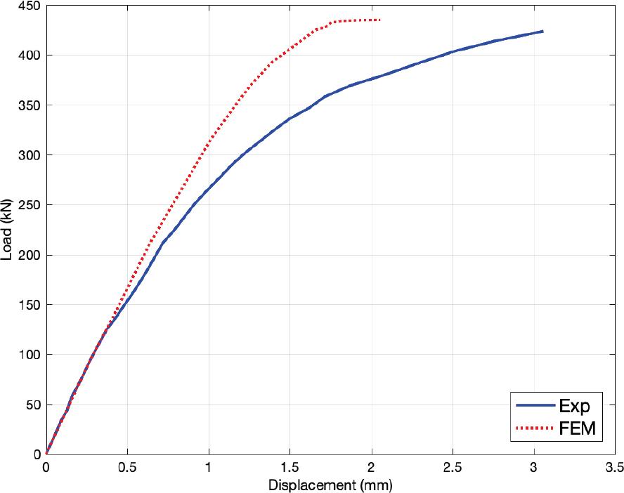
Comparison of experimental and numerical load–displacement curves for the control beam
Source: own work.
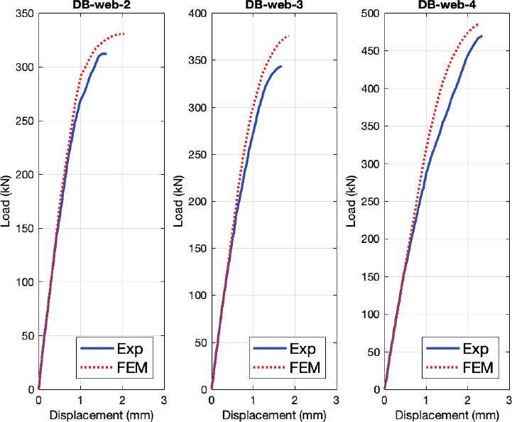
Load–displacement curves comparison for a beam with steel plates as web reinforcement
Source: own work.
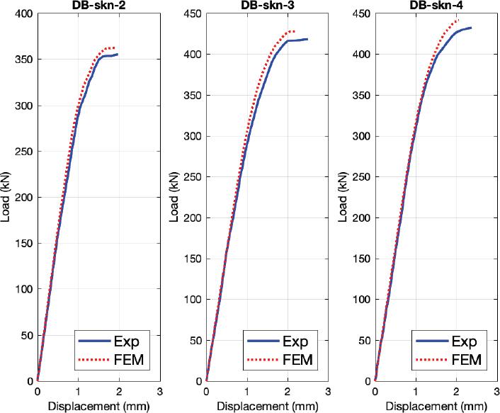
Load–displacement curves comparison for a beam with steel plates as skin reinforcement
Source: own work.
Comparison of the ultimate load between the experimental test and the numerical simulation
| Beam | Pu exp [kN] | Pu FEM [kN] | Increase in FEM over experimental [%] |
|---|---|---|---|
| DB-control | 425 | 435 | 2.3 |
| DB-web-2 | 312 | 330 | 5.7 |
| DB-web-3 | 344 | 376 | 9.3 |
| DB-web-4 | 470 | 486 | 3.4 |
| DB-skn-2 | 355 | 362 | 1.9 |
| DB-skn-3 | 418 | 427 | 2.1 |
| DB-skn-4 | 432 | 441 | 2.0 |
Source: own work.
The validated numerical model was used to conduct another case where the steel plates were used as equivalent for skin and web reinforcement, which was not done experimentally. Based on the experiment, DB-web-4 showed the best structural performance based on ultimate load and crack pattern. This specimen was selected to perform additional analysis. Three new cases from DB-web-4 were simulated, which combine the 4 mm web steel plates reinforcement with 2 mm, 3 mm, and 4 mm as skin reinforcement. Figure 11 shows the load displacement curves for the new cases DB-web4-skn2, DB-web4-skn3, and DB-web4-skn4. From this figure, there is no significant difference among these cases. It can be concluded that web reinforcement is governing the behavior of the deep beam over the skin reinforcement.
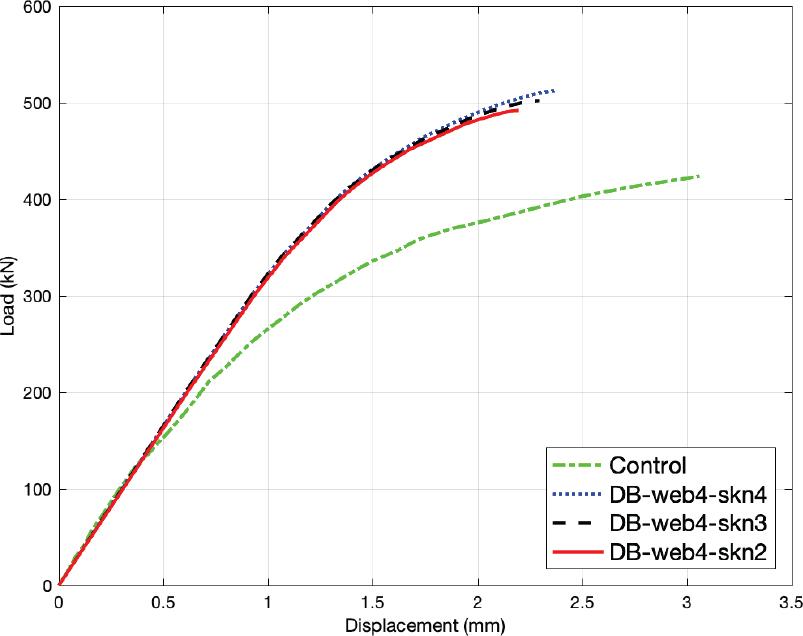
Load–displacement curves for a combination of web and skin reinforcement
Source: own work.
This research investigated the structural behavior and shear efficiency of self-compacted reinforced concrete deep beam incorporating steel plates as an alternative to conventional stirrups and skin reinforcement. The following conclusions can be drawn from the research:
– The experimental results showed that the effectiveness of replacing traditional shear reinforcement with steel plates is highly dependent on plate thickness.
– The use of 4 mm-thick steel plates as web reinforcement resulted in an 11% increase in ultimate capacity compared with the control.
– The beams with a 2 mm and a 3 mm steel plates as web reinforcement exhibited decreases in the ultimate load of 26% and 19% respectively, compared to the control specimen.
– The incorporation of steel plates with varying thicknesses as skin reinforcement yielded results comparable to those of the control beam, suggesting that structural integrity was maintained without significant degradation.
– The finite element analysis showed good agreement with experimental data, confirming the reliability of the proposed reinforcement technique.
– This study concludes that steel plates serve as a viable and effective alternative to conventional shear reinforcement in SCC reinforced deep beams, with optimal structural performance achieved through the implementation of 4 mm-thick web plates.